EP4175086A1 - Utilisation d'un système de tubes vides - Google Patents
Utilisation d'un système de tubes vides Download PDFInfo
- Publication number
- EP4175086A1 EP4175086A1 EP22202081.0A EP22202081A EP4175086A1 EP 4175086 A1 EP4175086 A1 EP 4175086A1 EP 22202081 A EP22202081 A EP 22202081A EP 4175086 A1 EP4175086 A1 EP 4175086A1
- Authority
- EP
- European Patent Office
- Prior art keywords
- empty pipe
- housing
- floor
- building
- empty
- Prior art date
- Legal status (The legal status is an assumption and is not a legal conclusion. Google has not performed a legal analysis and makes no representation as to the accuracy of the status listed.)
- Pending
Links
Images



Classifications
-
- H—ELECTRICITY
- H02—GENERATION; CONVERSION OR DISTRIBUTION OF ELECTRIC POWER
- H02G—INSTALLATION OF ELECTRIC CABLES OR LINES, OR OF COMBINED OPTICAL AND ELECTRIC CABLES OR LINES
- H02G1/00—Methods or apparatus specially adapted for installing, maintaining, repairing or dismantling electric cables or lines
-
- H—ELECTRICITY
- H02—GENERATION; CONVERSION OR DISTRIBUTION OF ELECTRIC POWER
- H02G—INSTALLATION OF ELECTRIC CABLES OR LINES, OR OF COMBINED OPTICAL AND ELECTRIC CABLES OR LINES
- H02G9/00—Installations of electric cables or lines in or on the ground or water
- H02G9/06—Installations of electric cables or lines in or on the ground or water in underground tubes or conduits; Tubes or conduits therefor
-
- E—FIXED CONSTRUCTIONS
- E03—WATER SUPPLY; SEWERAGE
- E03B—INSTALLATIONS OR METHODS FOR OBTAINING, COLLECTING, OR DISTRIBUTING WATER
- E03B7/00—Water main or service pipe systems
- E03B7/04—Domestic or like local pipe systems
-
- G—PHYSICS
- G02—OPTICS
- G02B—OPTICAL ELEMENTS, SYSTEMS OR APPARATUS
- G02B6/00—Light guides; Structural details of arrangements comprising light guides and other optical elements, e.g. couplings
- G02B6/46—Processes or apparatus adapted for installing or repairing optical fibres or optical cables
- G02B6/50—Underground or underwater installation; Installation through tubing, conduits or ducts
-
- G—PHYSICS
- G02—OPTICS
- G02B—OPTICAL ELEMENTS, SYSTEMS OR APPARATUS
- G02B6/00—Light guides; Structural details of arrangements comprising light guides and other optical elements, e.g. couplings
- G02B6/46—Processes or apparatus adapted for installing or repairing optical fibres or optical cables
- G02B6/50—Underground or underwater installation; Installation through tubing, conduits or ducts
- G02B6/501—Underground or underwater installation; Installation through tubing, conduits or ducts underground installation of connection boxes
-
- H—ELECTRICITY
- H02—GENERATION; CONVERSION OR DISTRIBUTION OF ELECTRIC POWER
- H02G—INSTALLATION OF ELECTRIC CABLES OR LINES, OR OF COMBINED OPTICAL AND ELECTRIC CABLES OR LINES
- H02G3/00—Installations of electric cables or lines or protective tubing therefor in or on buildings, equivalent structures or vehicles
- H02G3/02—Details
- H02G3/04—Protective tubing or conduits, e.g. cable ladders or cable troughs
- H02G3/0462—Tubings, i.e. having a closed section
- H02G3/0481—Tubings, i.e. having a closed section with a circular cross-section
-
- H—ELECTRICITY
- H02—GENERATION; CONVERSION OR DISTRIBUTION OF ELECTRIC POWER
- H02G—INSTALLATION OF ELECTRIC CABLES OR LINES, OR OF COMBINED OPTICAL AND ELECTRIC CABLES OR LINES
- H02G3/00—Installations of electric cables or lines or protective tubing therefor in or on buildings, equivalent structures or vehicles
- H02G3/02—Details
- H02G3/06—Joints for connecting lengths of protective tubing or channels, to each other or to casings, e.g. to distribution boxes; Ensuring electrical continuity in the joint
-
- H—ELECTRICITY
- H02—GENERATION; CONVERSION OR DISTRIBUTION OF ELECTRIC POWER
- H02G—INSTALLATION OF ELECTRIC CABLES OR LINES, OR OF COMBINED OPTICAL AND ELECTRIC CABLES OR LINES
- H02G3/00—Installations of electric cables or lines or protective tubing therefor in or on buildings, equivalent structures or vehicles
- H02G3/02—Details
- H02G3/06—Joints for connecting lengths of protective tubing or channels, to each other or to casings, e.g. to distribution boxes; Ensuring electrical continuity in the joint
- H02G3/0616—Joints for connecting tubing to casing
-
- H—ELECTRICITY
- H02—GENERATION; CONVERSION OR DISTRIBUTION OF ELECTRIC POWER
- H02G—INSTALLATION OF ELECTRIC CABLES OR LINES, OR OF COMBINED OPTICAL AND ELECTRIC CABLES OR LINES
- H02G9/00—Installations of electric cables or lines in or on the ground or water
- H02G9/10—Installations of electric cables or lines in or on the ground or water in cable chambers, e.g. in manhole or in handhole
Definitions
- the present invention relates to the use of an empty pipe system for installation in the ground.
- the installation in the ground takes place in the immediate vicinity of a building, i.e. on its property.
- the empty pipe system is built into the ground, for example, in the garden of the building or in the area of a driveway or access routes.
- the use of empty pipes when connecting a building is known, namely the individual media lines (e.g. for electricity, water and possibly gas) are laid in empty pipes between a street-side connection point and the building. So they extend in the ground towards the building and into the building via a so-called house lead-in.
- the house lead-in then forms part of the so-called house connection, which, depending on the medium, can also include a meter and distributor, for example.
- the present invention is based on the technical problem of specifying an advantageous use of an empty pipe system or an advantageous empty pipe system as the subject of the use.
- the corresponding empty pipe system has at least two empty pipes and additionally at least one floor housing. It is installed in the ground such that a first conduit connects a first base enclosure to the building and a second conduit (different from the first) extends away from the base enclosure. Furthermore, a media line is laid in the empty pipe system, which, in contrast to the example at the beginning, does not connect the building, but leads the corresponding medium out of the building, i.e. makes it available in the garden or generally on the property outside the building. In contrast to the example above, the media line is in the building not connected to the supply end, but to the consumer end of the media house connection.
- the medium is thus made available outside the building, which can in particular be a residential building, preferably a single-family house, on its property.
- a corresponding consumer or consumer connection can then be placed there (which is supplied from the building via the media line), e.g. a power or water connection or also a data connection.
- an electric lawn mower or its charger or a charging station in general e.g. B. for an electric vehicle (" wall box ”) , or z. B.
- a lighting unit such as a lamp, or a heat pump can be operated or a data/WLAN supply can be created outdoors.
- the empty pipe system used for laying the media line also has the floor housing, which can serve as an access point, for example. In comparison to a continuous empty pipe, it can e.g. It would be easier, for example, to gradually thread or pull the media line through, e.g. in a first step between the floor housing and the building and then in a second step in the second empty pipe.
- the interior space available with the base housing can also be used to accommodate connection and, in particular, branching points of the media line.
- two sections of the media line which then z. B. run away from the bottom housing in different empty tubes, be connected to each other.
- a fitting connection of empty pipes
- a clamp capable, in particular electric cable
- the bottom housing has a side wall that horizontally delimits its housing interior. It can generally also be open at the bottom, but it preferably has a bottom wall that is one piece with the side wall and delimits the housing interior at the bottom.
- the housing interior can, for example, have a volume of at least 2 liters, 3 liters or 4 liters; 20 liters, 15 liters, 10 liters or 8 liters. In this way, on the one hand, sufficient space can be available for the functions described above, but on the other hand, installation in the floor does not require excessive effort.
- the empty tubes open into the interior of the housing; for this purpose they are preferably attached, in particular pushed in, to a respective connection point of the base housing (see below in detail).
- the empty pipes can also run into the bottom housing from below, ie connection points can be provided in its bottom wall. However, they preferably run into the floor housing with at least a partial horizontal extension, preferably essentially parallel to the horizontal, which can reduce the installation depth, for example, and can be of particular interest in the end customer segment.
- a respective empty pipe can be made in one piece or from several pieces that are put together, e.g. B. connected to each other via a respective socket or a fitting, be constructed of empty pipe sections. This applies analogously to the media line, which can be constructed continuously or from a number of line sections which are functionally connected to one another, ie conducting the corresponding medium.
- the first and second empty pipe in a preferred embodiment open out at an angle to one another into the bottom case.
- “Angled” does not mean parallel, they can, for example, enclose an angle of at least 30°, 60° or 80°, with possible upper limits being at most 150°, 120° or 100°, for example.
- they can form an L-shape with one another or, if a third empty tube is provided (see below), also a T-shape.
- more than three empty pipes can also be connected, which then extend in a star shape, in particular four empty pipes in a cross shape.
- the base housing is or is installed in the base in such a way that a cover delimiting the housing interior at the top lies below an upper edge of the finished base structure.
- the cover can, for example, be offset downwards by at least 1 cm, 3 cm or 5 cm, with possible upper limits which should be disclosed independently of this being, for example, at most 30 cm or 20 cm.
- the upper edge is the surface of the top layer of soil, which depending on the position on the property of bulk material, z. As gravel or topsoil, or a paving can be formed.
- the built-in floor housing is then, for example, surrounded on all sides with floor material, preferably at least in part with bulk material, optionally at least in part with concrete or a slab covering.
- the cover can, for example, form a cover wall which can be formed in one piece, in particular monolithically, with the side wall.
- One-piece means non-destructively separable, "monolithic” means made of the same continuous material.
- the cover wall can then be knocked out and, if required, later replaced with another cover or assembly attachment.
- a cover that can be removed and put on again in a reversible manner can also be provided (already when installing the base housing), which can be screwed to the side wall, for example, or preferably latched to it.
- a floor area above the cover is removed in a later stage of the method or assembly, ie, depending on the floor covering, it is dug up and/or a plaster covering is removed.
- the bottom case is exposed so that the lid is accessible from above.
- the lid is then preferably removed, e.g. B. for laying work, i.e. for pulling or pushing the media line. This means that the interior of the housing is accessible from above and the media line can be pushed into the empty pipe or taken out of it.
- the opening of the cover can also be used for connection or branching work on the media line, e.g.
- a cable (electrical or data cable) can be branched and the branching point (terminal, especially in the junction box/cable housing) can be accommodated in the interior of the housing .
- the bottom housing can also be closed again afterwards and the bottom can be restored above.
- a consumer or consumer connection is placed on the base housing, with the base housing being used as a base. Since it is already in the ground anyway, it creates stability and can be used for anchoring.
- a mounting attachment is preferably placed on the base housing, particularly preferably in exchange for the cover.
- the mounting attachment can be made comparatively solid, for example made of a hard plastic or polymer concrete. Regardless of the material in detail, the consumer or consumer connection can then be screwed onto the mounting attachment, e.g. using a pedestal (which then carries the actual consumer/consumer connection, cf Figures 3c , 4c for illustration).
- one end of the first empty tube is placed at a first connection point and/or one end of the second empty tube is placed at a second connection point of the first floor housing, the respective empty tube latching at the respective connection point.
- the end of the empty pipe is preferably pushed into the connection point and the locking means engages in the outer wall surface of the empty pipe, so that, for example, a free cross-section is available for laying the cables.
- the first and/or second connection point is previously closed with a blind plug, which is removed when or before the respective empty pipe is attached.
- the blind plug is preferably formed monolithically with the remainder of the base housing, preferably monolithically with its side wall (if the connection point is in the side wall, which is preferred).
- the equipment with the blind plug creates flexibility, a user can decide on site, for example, depending on the soil conditions, from which side he connects the empty pipe to the floor housing.
- connection housing preferably has a further connection point, ie a total of at least three connection points (and, for example, no more than eight or six), particularly preferably four connection points, which are more preferably arranged in the shape of a cross when viewed from above. Irrespective of the number in detail, in the initial state all connection points can preferably be closed with a blind plug. When the floor housing is installed and connected in the floor, the blanking plugs are then removed according to the number of empty pipes. All connection points can be occupied or one or more can be unoccupied and remain closed.
- connection point can preferably be equipped both with the latching means (see above) and with the blind plug, the latter then preferably covering the latching means on the outside (towards the outside of the housing), so that the latching means can be protected from dirt, etc.
- more than two empty pipes can be connected to the first floor housing, ie a third and optionally also a fourth empty pipe (with regard to possible upper limits cf. the comments on the connection points).
- a third and optionally also a fourth empty pipe (with regard to possible upper limits cf. the comments on the connection points).
- three empty pipes can be connected in a T-shape or four empty pipes can be connected in a cross-shaped manner when viewed from above.
- the media line can be routed via the first empty pipe into the first floor housing and divided there into the second and third (and possibly fourth) empty pipe.
- the base housing is arranged on an erection device which supports and holds the base housing in position when it is installed in the ground.
- the erection device thus specifies the position of the base housing when it is filled with soil material and/or concrete.
- a ditch for example, can be excavated prior to this refilling, in which case the installation device can then, in principle, hold the floor housing in a self-supporting manner.
- the installation device can have a stand, for example with a comparatively large base part or, in particular, with a ground spike. The latter can be driven into the ground, which creates stability.
- the base housing can be mounted, for example screwed, to the end of the erection device that is vertically opposite the stand or ground spike.
- the installation device is preferably designed to be height-adjustable, so that the vertical position of the base housing can be adjusted before it is filled with soil material. This allows the position of the floor housing to be easily adjusted to the desired height from the top edge of the finished floor structure, see also the comments above.
- the height adjustability can be implemented, for example, with rods that can be displaced relative to one another in the vertical direction, for example with a telescopic mechanism.
- the empty pipe system has a second floor housing, which is or will be connected to the first floor housing via the second empty pipe.
- the second empty pipe can connect the two floor housings directly to one another, so that one end is connected to the first floor housing and its other, opposite end is connected to the second floor housing.
- the connection can also be made via one or more additional empty pipes, and optionally via one or more additional floor housings.
- a respective empty pipe can have a length, for example of at least 1.5 m, preferably at least 2 m, with possible upper limits being, for example, at most 15 m, 12 m, 10 m, 8 m or 6 m.
- the floor housings can be spaced apart from one another at a corresponding distance, taken along the respective empty pipe.
- the empty pipe system can also have more than two floor housings, e.g. at least four or five floor housings (with possible upper limits of e.g. a maximum of 25, 15 or 10), which are then connected to one another on the property with the empty pipes are, form a network.
- a respective floor housing can be used "only" as an intermediate point for the laying of cables and/or the positioning of a consumer/consumer connection.
- a third empty pipe can be provided, which connects the second floor housing to the building. This means that access from the building is possible not only via the first empty pipe (and the first floor housing), but also via the third empty pipe and the second floor housing.
- the first and third empty pipe can preferably be connected to the building on different sides of the building, that is to say on different outsides of the building when viewed from above (which can be offset by 90° or opposite one another, for example).
- the ground housings are placed along a border and/or path on the property.
- the edging can, for example, be the property boundary itself, but it can also be a boundary between different areas on the property, such as a bed edging, etc.
- the surface of the path can be formed, for example, from compacted gravel or, in particular, a paving surface. Irrespective of these details, the floor housings positioned along the path/enclosure, which in particular can be arranged equidistantly, e.g. B. a possibility for the later positioning of lights can be created.
- a plurality of floor housings are generally positioned relative to one another, in particular along a path and/or an enclosure, not only a horizontal, but also a vertical alignment relative to one another can be of interest and advantage.
- the ground housings can be aligned along a batter board or even a laser or other alignment line, for example if the path or enclosure has a slope.
- connection housings can be achieved particularly well if they are each arranged on a mounting device, in particular a height-adjustable mounting device (see front in detail).
- the empty pipe system has at least three, four or five floor housings that are structurally identical to one another. When installed in the floor, they can then be individually adjusted, e.g. by removing blind plugs, see above. Despite the (partial) identical construction, there can also be floor housings of different designs when considering the empty pipe system as a whole, for example for paved/paved areas (see below).
- the empty pipe system is built into the ground before a garden is laid out on the property.
- a garden is laid out on the property.
- the garden is laid out, i.e. paths and terrace areas are created and planting areas are laid out.
- the laying of the media line is then preferably carried out only afterwards, in particular only then is the consumer/consumer connection mounted (see above). This sequence can be advantageous, for example, in that the media line is less likely to be damaged by garden work.
- the empty pipe system has a casting body that is cast into a base plate of an adjacent building on the outside of the building.
- the outbuilding can be a garden shed or preferably a garage.
- the grout is positioned before the outbuilding is erected and then keeps a through opening free in the concrete floor slab, with one or more empty pipes opening into the grout from below.
- the cast body is connected to the rest of the empty pipe system, so the garage itself can be connected to the media supply and/or used for sub-distribution.
- the invention also relates to an installation arrangement which preferably results as a result of an installation as described here.
- Part of the installation arrangement can in particular also be the property and the building itself.
- figure 1 shows a plot of land 1 in a plan on which a building 2 stands, in this case a single-family home. Furthermore, 1 outbuilding 3, namely a garage 4 and a garden shed 5 are built on the property. In front of the garage 4 there is a driveway 6 which borders on a street 7 .
- the building 2 is equipped with a house version 8, which is cast into the floor slab of the building 2 in the present example. Empty conduits 9 extend away from the house structure 8, these run underneath the floor slab of the building 2 and lead to the outside area 10.
- An empty pipe system 20 is built into the floor there, which serves to open up the outside area 10 from the building 2 . This can be used, for example, to supply electricity, water or data outside of building 2, see details below.
- the empty pipe system 20 has a first empty pipe 21, a second empty pipe 22 and a first base housing 31, the following description initially referring to the part at the bottom left in FIG figure 1 relates.
- the first floor housing 31 is connected via the second empty pipe 22 to a second floor housing 32, which is connected to the building 2 via a third empty pipe 23, specifically on a different side 2.2 than the first floor housing 31.
- a fourth empty pipe 24 is also a third floor housing 33 is connected, which is structurally identical to the first and second floor housing 31, 32, but in contrast to this is used as the end point of the empty pipe system 20.
- the third empty pipe 23 could also be considered as the first empty pipe and the first as the third, in which case the numbering of the bottom housing would then also be reversed accordingly.
- first empty pipes 21 in the empty pipe system 20 namely a further first empty pipe 21.1 extends away from the side 2.3 of the building 2. This is connected to a further first floor housing 31.1, and this is connected to a further second floor housing 32.1 via a further second empty pipe 22.1.
- a further third floor housing 33.1 is connected via a further fourth empty pipe 24.1, the further fourth empty pipe 24.1 being part of a cable protection pipe system, see below in detail.
- the additional floor housing 31.1-33.1 can, as indicated schematically, be placed along a garden path 16, for example, and/or on a bed border, so that later z. B. a series of lights can be installed.
- An additional first empty pipe 21.2 is installed on the building side 2.4, which has an additional first floor housing 31.2 and above it additional empty pipes and floor housings 22.2, 24.2, 25; 32.2, 33.2, 34 connects.
- the additional first floor housing 31.2 is connected to the building 2 not only via the additional first empty pipe 21.1, but via an interposed cast body 18.
- the casting body 18 is pot-shaped like the house version 8 (cf. also figure 6 for illustration) and is concreted into the floor slab of garage 4.
- the empty pipes 19 connected to it run below the base plate and then outside of the garage 4 in the ground.
- the floor housings 35 differ from the floor housings discussed so far in their construction and installation, namely they are each constructed from a surface box and are not concealed in the ground, but installed flush with the ground.
- DN75 75 mm
- cable protection pipes 26 with a smaller diameter can also be connected to the floor housing; in the case of the additional second floor housing 31.2, a cable protection pipe system 27 is provided.
- This has a uniform connecting piece 28 from which two cable protection tubes 26 extend away. In the present case, their ends are positioned freely in the garden, where a charging station for a robotic lawnmower, for example, can later be placed.
- a connecting piece can also be arranged at the opposite end and the cable protection pipe system can also be connected to a floor housing there, see above.
- connection points 45.1-45.4 are provided on it.
- the first connection point 45.1 is used, where the fourth empty tube 24 is connected.
- the remaining connection points 45.2-45.4 remain unused, they are each closed with a one-piece blind plug. This protects the interior of the housing and the respective connection point can be made usable by removing the blind plug. So that's how it is Figure1 visible, any connection or empty pipe combination possible, so the floor housing can not only be used as an end point, but also as a passage point (cf. middle above in figure 1 ) or L- or T-shaped connector can be used.
- the empty pipe system 20 according to figure 2 corresponds in its basic structure to that according to figure 1 .
- the same parts or parts with the same function are referenced with the same reference symbols and in this respect we always refer to the description of the other figures.
- the floor housings correspond to figure 2 those out of figure 1 , but in contrast to this, they are divided into different types, so they are not structurally identical to one another.
- connection points 51 There are end points 51 that have only exactly one connection point 45.1.
- passage pieces 52 which have connection points 45.1, 45.3 on opposite sides.
- connection points 45.1, 45.3 There are also L-shaped connecting pieces 53 with connecting points 45.1, 45.2 angled towards one another, and cross-shaped connecting pieces 54 with a connecting point 45.1-45.4 on all sides.
- these floor housings are not adapted on site by removing the blanking plugs, but are already provided for in the planning and assembled in advance.
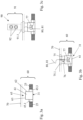
- the figures 3a -c illustrate a first bottom housing 31 in a schematic side view.
- An empty pipe 25 laid in the floor 60 is connected to two connection points 45.1, 45.3, which can be any empty pipe of the empty pipe system 20.
- the empty pipes 25 are pushed into the respective connection point 45.1, 45.3 and locked therein.
- a housing interior 61 of the base housing 31 is delimited horizontally by a side wall 62 in which the connection points 45.1, 45.3 are arranged, and vertically by a cover wall 63 formed monolithically with the side wall 62. This forms a cover 65, and the base housing 31 is installed in the base 60 so that it lies below an upper edge 70 of the base.
- Figure 3b shows a according to the blind advance Figure 3a subsequent assembly stage.
- the cover 65 ie the cover wall 63, was removed.
- a mounting attachment 75 is fitted, the top edge of which is essentially flush with the top edge 70 of the base 60 .
- the mounting attachment 75 is a solid body, for example made of hard plastic or polymer concrete. In the present example, it has a flange 75.1 at its upper end, with which it rests in the floor 60, which prevents it from slipping into the interior space 61 of the housing.
- the mounting attachment 75 can also be attached to the base housing 31 (not shown here).
- a media line 80 is laid, in this case a data cable 81.
- the media line 80 is connected in the building 2 to the consumer-side end of a house connection, and the empty pipe system 20 is used for laying on the outside of the building.
- the base housing 31 or the housing interior 61 is also used for distribution, namely a cable housing 77 is arranged there, in which the media line 80 is branched further in the empty pipe system.
- the mounting attachment 75 has a through-opening 76 through which the media line 80 is threaded before the mounting attachment 75 is positioned.
- Figure 3c shows a subsequent assembly stage, on the assembly attachment 75 a consumer or consumer connection 90 is mounted, in this case a pedestal 91 with sockets 92.
- This has a flange 91.1, which is screwed to the assembly attachment 75.
- the sockets 92 are exemplary; a charging station for electric vehicles or another type of consumer in general could also be connected, such as a garden shower in the case of a water pipe (or a water tap, etc.).
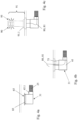
- the figures 4a -c show a floor housing in different stages of expansion, with only the differences being discussed in depth below.
- the bottom housing 31 is also closed with a cover 65, but in the present case it is designed as a cover 83 that can be removed and inserted reversibly.
- only one empty tube 25 is connected to the bottom housing 31 in the example shown. Accordingly, the housing interior 61 is not used for sub-distribution, but the media line 80 in Figure 4b routed directly out of the mounting attachment 75 (no cable housing).
- a lamp 95 is installed as the consumer or consumer connection 90 , which is also supported by a pedestal 91 .
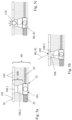
- the Figures 5a -c show an alternative bottom housing 35, which is constructed from a surface box 100 and a base 101.
- the street cap 100 is height-adjustable, so it is divided into an upper part 100.1 and a lower part 100.2, with the former being slidably guided (telescopically) on the latter to adjust a vertical construction height.
- the floor housing 35 is also installed in the floor 60, with its upper edge 70 being formed here by paving stones 105 (cf. also the positions of the driveway 6 in Figs figures 1 and 2 ).
- a mounting attachment 105 was placed in the upper part 100.1 of the surface box 100.
- a cover (not shown) previously closing the upper part 100.1 was removed and replaced by the assembly insert 100.1.
- the latter is framed at the top with a recess 106 into which a floor lamp 110 is then inserted.
- FIG 6 shows a house design 120, which has a pot-shaped structural component 121. This is poured into the base plate 123 when the building 2 is erected, the empty pipes 9 being connected from below and, as can be seen from the supervisions according to FIG figures 1 and 2 visible, run on different sides of building 2. After the base plate 123 has been concreted, a wall 124 is erected on it, and a sealing insert 124 can later be inserted into the shell component 121 . This then seals the media line laid in the empty pipe system 20 (not shown here) against the shell component 120.
Landscapes
- Details Of Indoor Wiring (AREA)
Applications Claiming Priority (1)
| Application Number | Priority Date | Filing Date | Title |
|---|---|---|---|
| DE102021128308.6A DE102021128308A1 (de) | 2021-10-29 | 2021-10-29 | Verwendung eines leerrohrsystems |
Publications (1)
| Publication Number | Publication Date |
|---|---|
| EP4175086A1 true EP4175086A1 (fr) | 2023-05-03 |
Family
ID=83898515
Family Applications (1)
| Application Number | Title | Priority Date | Filing Date |
|---|---|---|---|
| EP22202081.0A Pending EP4175086A1 (fr) | 2021-10-29 | 2022-10-18 | Utilisation d'un système de tubes vides |
Country Status (2)
| Country | Link |
|---|---|
| EP (1) | EP4175086A1 (fr) |
| DE (2) | DE102021128308A1 (fr) |
Citations (4)
| Publication number | Priority date | Publication date | Assignee | Title |
|---|---|---|---|---|
| US5796037A (en) * | 1995-10-12 | 1998-08-18 | Walker Systems, Inc. | Shallow recessed floor box |
| US20150037096A1 (en) * | 2013-07-31 | 2015-02-05 | Verizon Patent And Licensing Inc. | Sidewalk trench system |
| EP3249127B1 (fr) * | 2016-05-27 | 2019-09-11 | Kp1 | Prédalle comprenant au moins une incorporation et procédé de fabrication d'un plancher à l aide d'une telle prédalle |
| DE202019001267U1 (de) * | 2019-03-19 | 2020-06-25 | Hauff-Technik Gmbh & Co. Kg | Anschlussgehäusevorrichtung |
-
2021
- 2021-10-29 DE DE102021128308.6A patent/DE102021128308A1/de active Pending
-
2022
- 2022-10-18 EP EP22202081.0A patent/EP4175086A1/fr active Pending
- 2022-10-18 DE DE202022003231.5U patent/DE202022003231U1/de active Active
Patent Citations (4)
| Publication number | Priority date | Publication date | Assignee | Title |
|---|---|---|---|---|
| US5796037A (en) * | 1995-10-12 | 1998-08-18 | Walker Systems, Inc. | Shallow recessed floor box |
| US20150037096A1 (en) * | 2013-07-31 | 2015-02-05 | Verizon Patent And Licensing Inc. | Sidewalk trench system |
| EP3249127B1 (fr) * | 2016-05-27 | 2019-09-11 | Kp1 | Prédalle comprenant au moins une incorporation et procédé de fabrication d'un plancher à l aide d'une telle prédalle |
| DE202019001267U1 (de) * | 2019-03-19 | 2020-06-25 | Hauff-Technik Gmbh & Co. Kg | Anschlussgehäusevorrichtung |
Non-Patent Citations (5)
| Title |
|---|
| FACHSCHRIFTEN: "Strom im Garten mit Leerrohr für Erdkabel | Hausbauhelden.de", 4 August 2021 (2021-08-04), XP093215429, Retrieved from the Internet <URL:https://web.archive.org/web/20210804080642/https://www.hausbauhelden.de/ratgeber-aussenanlagen/leerrohr-fuer-erdkabel/> [retrieved on 20241016] * |
| HAUFF TECHNIK: "ETGAR - Energy to garden", 17 August 2021 (2021-08-17), XP093215531, Retrieved from the Internet <URL:https://www.h-gr-beilage.de/fileadmin/gesellschafter/gr-beilage/Produkte/Unsere_Marken/hauff/ETGAR_210817.pdf> [retrieved on 20241016] * |
| HAUFF TECHNIK: "Installation instructions - Basic unit 2LINE G-BOX", 5 August 2021 (2021-08-05), XP093216414, Retrieved from the Internet <URL:https://db.hauff-technik.de/files/740/4/3030353628_MA_G-BOX_GRUNDK_RPER_EN_GC.PDF> [retrieved on 20241018] * |
| HAUFF-TECHNIK ET AL: "ETGAR", 19 October 2021 (2021-10-19), XP093215460, Retrieved from the Internet <URL:https://web.archive.org/web/20211019234923/https://www.energytogarden.de/> [retrieved on 20241016] * |
| PREFABAT: "L'éLectricité préfabriquée au service des électriciens", 1 January 2011 (2011-01-01), Gerardmer (FR), pages 1 - 15, XP055443221, Retrieved from the Internet <URL:http://www.prefabat.fr/spip.php?action=acceder_document&arg=129&cle=340d046b577263491fabf7454118c6baeead3f07&file=pdf/Pieuvres-electriques-Prefabat.pdf> [retrieved on 20180122] * |
Also Published As
| Publication number | Publication date |
|---|---|
| DE102021128308A1 (de) | 2023-05-04 |
| DE202022003231U1 (de) | 2025-08-19 |
Similar Documents
| Publication | Publication Date | Title |
|---|---|---|
| EP3660990B1 (fr) | Procédé de fourniture d'une connexion de câble de données | |
| EP4175086A1 (fr) | Utilisation d'un système de tubes vides | |
| WO2021094420A1 (fr) | Utilisation d'un boîtier de raccordement | |
| DE202019001267U1 (de) | Anschlussgehäusevorrichtung | |
| DE10023399B4 (de) | Erschließungs-, Revisions- und Verteilerschacht mit Hausanschluß-Winkelplatte | |
| EP1414124B1 (fr) | Canal d'alimentation extérieur pour contenir des canalisations d'eau et/ou d'électricité | |
| EP4047766B1 (fr) | Agencement d'installation du bâtiment | |
| DE10233981A1 (de) | Hausanschlussschacht | |
| EP0976880B1 (fr) | Procédé et éléments pour installer des connections domestiques multiples | |
| EP3660991A1 (fr) | Dispositif de boitier de raccordement | |
| DE102025000117B3 (de) | Fundament für eine Kraftfahrzeug-Ladesäule | |
| DE202021004205U1 (de) | Gebäudeinstallationsanordnung | |
| DE102021104116A1 (de) | Gebäudeinstallationsanordnung | |
| DE10018432A1 (de) | Mehrfach-Kanalrohrsystem | |
| DE202021004206U1 (de) | Gebäudeinstallationsanordnung | |
| DE10156291B4 (de) | Vorrichtung zur Fixierung von Hausanschlussleitungen | |
| DE202021004207U1 (de) | Gebäudeinstallationsanordnung | |
| EP4148927B1 (fr) | Utilisation d'un dispositif logement | |
| DE202019002446U1 (de) | Anschlussgehäusevorrichtung | |
| DE3115653C2 (de) | Energieverteilerstation | |
| DE102022102651A1 (de) | Stützkonstruktionsanordnung für ein Wasserbecken | |
| WO2022175512A1 (fr) | Procédé pour fournir une liaison par câble de données | |
| DE3436073A1 (de) | Kupplungsstueck fuer einen kabelkanal | |
| EP3836327A1 (fr) | Utilisation pour connecter un point utilisateur de données ou de distribution de données | |
| DE102024106099A1 (de) | Anordnung und Verfahren zum Eingießen in eine Bodenplatte |
Legal Events
| Date | Code | Title | Description |
|---|---|---|---|
| PUAI | Public reference made under article 153(3) epc to a published international application that has entered the european phase |
Free format text: ORIGINAL CODE: 0009012 |
|
| STAA | Information on the status of an ep patent application or granted ep patent |
Free format text: STATUS: THE APPLICATION HAS BEEN PUBLISHED |
|
| AK | Designated contracting states |
Kind code of ref document: A1 Designated state(s): AL AT BE BG CH CY CZ DE DK EE ES FI FR GB GR HR HU IE IS IT LI LT LU LV MC ME MK MT NL NO PL PT RO RS SE SI SK SM TR |
|
| STAA | Information on the status of an ep patent application or granted ep patent |
Free format text: STATUS: REQUEST FOR EXAMINATION WAS MADE |
|
| 17P | Request for examination filed |
Effective date: 20230911 |
|
| RBV | Designated contracting states (corrected) |
Designated state(s): AL AT BE BG CH CY CZ DE DK EE ES FI FR GB GR HR HU IE IS IT LI LT LU LV MC ME MK MT NL NO PL PT RO RS SE SI SK SM TR |
|
| STAA | Information on the status of an ep patent application or granted ep patent |
Free format text: STATUS: EXAMINATION IS IN PROGRESS |
|
| 17Q | First examination report despatched |
Effective date: 20241029 |