EP4175119B1 - Motorisierte antriebsvorrichtung, verdunkelungsvorrichtung und steuerungsverfahren dafür - Google Patents
Motorisierte antriebsvorrichtung, verdunkelungsvorrichtung und steuerungsverfahren dafür Download PDFInfo
- Publication number
- EP4175119B1 EP4175119B1 EP22204013.1A EP22204013A EP4175119B1 EP 4175119 B1 EP4175119 B1 EP 4175119B1 EP 22204013 A EP22204013 A EP 22204013A EP 4175119 B1 EP4175119 B1 EP 4175119B1
- Authority
- EP
- European Patent Office
- Prior art keywords
- microcontroller
- control unit
- photovoltaic panel
- battery
- transistor
- Prior art date
- Legal status (The legal status is an assumption and is not a legal conclusion. Google has not performed a legal analysis and makes no representation as to the accuracy of the status listed.)
- Active
Links
Images


Classifications
-
- H—ELECTRICITY
- H02—GENERATION; CONVERSION OR DISTRIBUTION OF ELECTRIC POWER
- H02J—ELECTRIC POWER NETWORKS; CIRCUIT ARRANGEMENTS OR SYSTEMS FOR SUPPLYING OR DISTRIBUTING ELECTRIC POWER; SYSTEMS FOR STORING ELECTRIC ENERGY
- H02J7/00—Circuit arrangements for charging or discharging batteries or for supplying loads from batteries
- H02J7/34—Parallel operation in networks using both storage and other DC sources, e.g. providing buffering
- H02J7/35—Parallel operation in networks using both storage and other DC sources, e.g. providing buffering with light sensitive cells
-
- E—FIXED CONSTRUCTIONS
- E06—DOORS, WINDOWS, SHUTTERS, OR ROLLER BLINDS IN GENERAL; LADDERS
- E06B—FIXED OR MOVABLE CLOSURES FOR OPENINGS IN BUILDINGS, VEHICLES, FENCES OR LIKE ENCLOSURES IN GENERAL, e.g. DOORS, WINDOWS, BLINDS, GATES
- E06B9/00—Screening or protective devices for wall or similar openings, with or without operating or securing mechanisms; Closures of similar construction
- E06B9/56—Operating, guiding or securing devices or arrangements for roll-type closures; Spring drums; Tape drums; Counterweighting arrangements therefor
- E06B9/68—Operating devices or mechanisms, e.g. with electric drive
- E06B9/72—Operating devices or mechanisms, e.g. with electric drive comprising an electric motor positioned inside the roller
-
- H—ELECTRICITY
- H02—GENERATION; CONVERSION OR DISTRIBUTION OF ELECTRIC POWER
- H02J—ELECTRIC POWER NETWORKS; CIRCUIT ARRANGEMENTS OR SYSTEMS FOR SUPPLYING OR DISTRIBUTING ELECTRIC POWER; SYSTEMS FOR STORING ELECTRIC ENERGY
- H02J7/00—Circuit arrangements for charging or discharging batteries or for supplying loads from batteries
- H02J7/865—Battery or charger load switching, e.g. concurrent charging and load supply
-
- H—ELECTRICITY
- H02—GENERATION; CONVERSION OR DISTRIBUTION OF ELECTRIC POWER
- H02J—ELECTRIC POWER NETWORKS; CIRCUIT ARRANGEMENTS OR SYSTEMS FOR SUPPLYING OR DISTRIBUTING ELECTRIC POWER; SYSTEMS FOR STORING ELECTRIC ENERGY
- H02J7/00—Circuit arrangements for charging or discharging batteries or for supplying loads from batteries
- H02J7/90—Regulation of charging or discharging current or voltage
- H02J7/96—Regulation of charging or discharging current or voltage in response to battery voltage
-
- E—FIXED CONSTRUCTIONS
- E06—DOORS, WINDOWS, SHUTTERS, OR ROLLER BLINDS IN GENERAL; LADDERS
- E06B—FIXED OR MOVABLE CLOSURES FOR OPENINGS IN BUILDINGS, VEHICLES, FENCES OR LIKE ENCLOSURES IN GENERAL, e.g. DOORS, WINDOWS, BLINDS, GATES
- E06B9/00—Screening or protective devices for wall or similar openings, with or without operating or securing mechanisms; Closures of similar construction
- E06B9/24—Screens or other constructions affording protection against light, especially against sunshine; Similar screens for privacy or appearance; Slat blinds
- E06B2009/2476—Solar cells
-
- E—FIXED CONSTRUCTIONS
- E06—DOORS, WINDOWS, SHUTTERS, OR ROLLER BLINDS IN GENERAL; LADDERS
- E06B—FIXED OR MOVABLE CLOSURES FOR OPENINGS IN BUILDINGS, VEHICLES, FENCES OR LIKE ENCLOSURES IN GENERAL, e.g. DOORS, WINDOWS, BLINDS, GATES
- E06B9/00—Screening or protective devices for wall or similar openings, with or without operating or securing mechanisms; Closures of similar construction
- E06B9/56—Operating, guiding or securing devices or arrangements for roll-type closures; Spring drums; Tape drums; Counterweighting arrangements therefor
- E06B9/68—Operating devices or mechanisms, e.g. with electric drive
- E06B2009/6809—Control
- E06B2009/6818—Control using sensors
-
- E—FIXED CONSTRUCTIONS
- E06—DOORS, WINDOWS, SHUTTERS, OR ROLLER BLINDS IN GENERAL; LADDERS
- E06B—FIXED OR MOVABLE CLOSURES FOR OPENINGS IN BUILDINGS, VEHICLES, FENCES OR LIKE ENCLOSURES IN GENERAL, e.g. DOORS, WINDOWS, BLINDS, GATES
- E06B9/00—Screening or protective devices for wall or similar openings, with or without operating or securing mechanisms; Closures of similar construction
- E06B9/56—Operating, guiding or securing devices or arrangements for roll-type closures; Spring drums; Tape drums; Counterweighting arrangements therefor
- E06B9/68—Operating devices or mechanisms, e.g. with electric drive
- E06B2009/6809—Control
- E06B2009/6818—Control using sensors
- E06B2009/6827—Control using sensors sensing light
-
- E—FIXED CONSTRUCTIONS
- E06—DOORS, WINDOWS, SHUTTERS, OR ROLLER BLINDS IN GENERAL; LADDERS
- E06B—FIXED OR MOVABLE CLOSURES FOR OPENINGS IN BUILDINGS, VEHICLES, FENCES OR LIKE ENCLOSURES IN GENERAL, e.g. DOORS, WINDOWS, BLINDS, GATES
- E06B9/00—Screening or protective devices for wall or similar openings, with or without operating or securing mechanisms; Closures of similar construction
- E06B9/56—Operating, guiding or securing devices or arrangements for roll-type closures; Spring drums; Tape drums; Counterweighting arrangements therefor
- E06B9/68—Operating devices or mechanisms, e.g. with electric drive
- E06B2009/6809—Control
- E06B2009/6818—Control using sensors
- E06B2009/6863—Control using sensors sensing wind speed
-
- H—ELECTRICITY
- H02—GENERATION; CONVERSION OR DISTRIBUTION OF ELECTRIC POWER
- H02J—ELECTRIC POWER NETWORKS; CIRCUIT ARRANGEMENTS OR SYSTEMS FOR SUPPLYING OR DISTRIBUTING ELECTRIC POWER; SYSTEMS FOR STORING ELECTRIC ENERGY
- H02J2105/00—Networks for supplying or distributing electric power characterised by their spatial reach or by the load
- H02J2105/40—Networks for supplying or distributing electric power characterised by their spatial reach or by the load characterised by the loads connecting to the networks or being supplied by the networks
- H02J2105/42—Home appliances
Definitions
- the present invention relates to a motorized drive device, in particular for a concealment device, in other words a motorized drive device for a concealment device, a concealment device comprising such a motorized drive device, as well as a method for controlling the operation of such a motorized drive device.
- the present invention relates to the field of occultation devices comprising a motorized drive device setting a screen in motion, between at least a first position and at least a second position.
- a motorized drive device comprises an electromechanical actuator of a movable closing, concealing or sun protection element, such as a shutter, a door, a grille, a blind or any other equivalent material, hereinafter called a screen.
- a movable closing, concealing or sun protection element such as a shutter, a door, a grille, a blind or any other equivalent material, hereinafter called a screen.
- the motorized drive device comprises an electromechanical actuator, an electronic control unit and an electrical energy supply device.
- the electromechanical actuator comprises an electric motor.
- the electrical energy supply device comprises a battery and a photovoltaic panel.
- the electronic control unit comprises a device for measuring a voltage supplied by the photovoltaic panel and a device for inhibiting the measuring device.
- the electronic control unit and the electric motor are supplied with electrical energy from the battery.
- the battery is supplied with electrical energy by means of the photovoltaic panel.
- the microcontroller comprises an input port for reading the voltage supplied by the photovoltaic panel and measured by the measuring device.
- this motorized drive device has the disadvantage of measuring an open-circuit voltage of the photovoltaic panel, from the measuring device, to determine a temperature, in order to compensate a control signal of the electric motor, the control signal being determined by means of a device for detecting a short-circuit current of the photovoltaic panel.
- the electric motor is controlled by the control signal which is dependent on the sunshine of the photovoltaic panel.
- the rotation speed of this electric motor is adjusted by the compensated control signal which is temperature dependent.
- this motorized drive device has the disadvantage of electrically disconnecting the electric motor from the photovoltaic panel, by means of a first switch, during the measurement of the no-load voltage of the photovoltaic panel by the measuring device, the measuring device being activated by means of a second switch.
- the second switch electrically disconnects the measuring device, when no measurement of the no-load voltage of the photovoltaic panel is implemented by the measuring device.
- This electrical disconnection of the measuring device during operation of the electric motor has the effect of reducing electrical energy losses in the measuring device compared to a case where the measuring device would remain electrically connected during operation of the electric motor.
- this motorized drive device has the disadvantage that the second switch of the inhibition device is mechanical.
- the document is also known US 2014/0145511 A1 which describes a motorized drive device.
- the motorized drive device comprises an electromechanical actuator, an electronic control unit and an electrical energy supply device.
- the electromechanical actuator comprises an electric motor.
- the electrical energy supply device comprises a battery and a photovoltaic panel.
- the electronic control unit comprises a device for measuring a voltage supplied by the photovoltaic panel.
- the electronic control unit and the electric motor are supplied with electrical energy from the battery.
- the battery is supplied with electrical energy by means of the photovoltaic panel.
- the microcontroller comprises an input port for reading the voltage supplied by the photovoltaic panel and measured by the measuring device.
- the present invention aims to solve the aforementioned drawbacks and to propose a motorized drive device, a concealment device comprising such a motorized drive device, as well as a method for controlling the operation of such a motorized drive device, making it possible to inhibit a device for measuring a voltage of a photovoltaic panel of an electrical energy supply device of the motorized drive device, while continuously maintaining the measuring device and the photovoltaic panel electrically connected.
- the inhibiting device is electrically connected, on the one hand, to the measuring device and, on the other hand, to the input port of the microcontroller.
- the inhibiting device comprises at least one transistor. Furthermore, the transistor is configured to force the input port of the microcontroller to a predetermined value, so as to block the value read by the input port of the microcontroller at the predetermined value.
- the transistor makes it possible to inhibit the voltage measuring device of the photovoltaic panel, while keeping the measuring device and the photovoltaic panel continuously electrically connected.
- the measuring device is at no time electrically disconnected from the photovoltaic panel by a cut-off device, such as a switch, as mentioned in the document. US 4 620 140 A .
- the transistor makes, in other words is configured to make, impossible a reading of a measurement of the voltage of the photovoltaic panel by the input port of the microcontroller, as soon as the transistor is activated, in other words as soon as the input port of the microcontroller is forced to the predetermined value.
- the transistor is configured to force the input port of the microcontroller to the predetermined value following the commissioning of the motorized drive device.
- the electronic control unit further comprises a diode.
- the diode is electrically connected, on the one hand, to the photovoltaic panel and, on the other hand, to the battery.
- the measuring device is connected electrically, on the one hand, to an electrical connection between the photovoltaic panel and the battery and, on the other hand, to a ground, in parallel to the photovoltaic panel and the battery.
- the measuring device is electrically connected to the photovoltaic panel and to the diode.
- the measuring device comprises at least one voltage divider bridge.
- the microcontroller further comprises at least one control output port of the transistor. Furthermore, the transistor is configured to force the input port of the microcontroller to the predetermined value following a forcing command to the predetermined value emitted by the output port of the microcontroller to the transistor.
- the electronic control unit further comprises a protective resistor, the protective resistor being electrically connected, on the one hand, to the output port of the microcontroller and, on the other hand, to the first pin of the transistor.
- the motorized drive device is in accordance with the invention and as mentioned above.
- the screen is configured to be driven in movement by the electromechanical actuator of the motorized drive device.
- This occultation device has characteristics and advantages similar to those described previously in relation to the motorized drive device according to the invention and as mentioned above.
- the occultation device further comprises a winding tube.
- the screen can be rolled up on the tube. winding.
- the winding tube is arranged to be rotated by the electromechanical actuator.
- the inhibiting device is electrically connected, on the one hand, to the measuring device and, on the other hand, to the input port of the microcontroller.
- the inhibiting device comprises at least one transistor.
- This control method has characteristics and advantages similar to those described previously in relation to the motorized drive device according to the invention and as mentioned above.
- the input port of the microcontroller is forced to the predetermined value by the transistor following the commissioning of the motorized drive device.
- the microcontroller further comprises at least one control output port of the transistor. Furthermore, the input port of the microcontroller is forced to the predetermined value by the transistor following a forcing command to the predetermined value emitted by the output port of the microcontroller to the transistor.
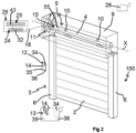
- This home automation installation 100 comprises at least one closing, concealing or solar protection device 3, according to one embodiment of the invention.
- This home automation installation 100 installed in a building, not shown, comprises an opening 1, in which is arranged a window 40 or a door, which is only shown in the figure 1 .
- This home automation installation 100 is equipped with at least one screen 2 belonging to the closing, concealment or solar protection device 3, in particular a motorized roller shutter.
- the closing, occulting or sun protection device 3 is hereinafter called “occulting device”.
- the occulting device 3 comprises the screen 2.
- the occultation device 3 may be a roller shutter, a canvas blind or one with adjustable slats, a rolling gate, a grille, a door or even a hinged shutter.
- the present invention applies to all types of occultation device.
- the occultation device 3 comprises a motorized drive device 5, in accordance with the invention.
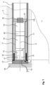
- the motorized drive device 5 comprises an electromechanical actuator 11 illustrated in figure 3 .
- the occultation device 3 further comprises a winding tube 4.
- the screen 2 can be rolled up on the winding tube 4.
- the winding tube 4 is arranged so as to be driven in rotation by the electromechanical actuator 11.
- the screen 2 of the occultation device 3 is wound on the winding tube 4 or unwound around it, the winding tube 4 being driven by the motorized drive device 5, in particular by the electromechanical actuator 11.
- the screen 2 is movable between a rolled-up position, in particular high, and an unrolled position, in particular low, and vice versa.
- the screen 2 of the occultation device 3 is a closing, occultation and/or sun protection screen, winding and unwinding around the winding tube 4, the inner diameter of which is greater than the outer diameter of the electromechanical actuator 11, so that the electromechanical actuator 11 can be inserted into the winding tube 4, when assembling the occultation device 3.
- the electromechanical actuator 11 in particular of the tubular type, makes it possible to rotate the winding tube 4 around an axis of rotation X, so as to move, in particular unroll or wind, the screen 2 of the occultation device 3.
- the electromechanical actuator 11 is inserted into the winding tube 4.
- the roller shutter which forms the concealment device 3
- the roller shutter comprises an apron comprising horizontal slats articulated to each other, forming the screen 2 of the roller shutter 3, and guided by two lateral slides 6, shown only in FIG. figure 2 These blades are joined when the apron 2 of the roller shutter 3 reaches its lower unrolled position.
- the rolled-up high position corresponds to the support of a final end blade 8, for example L-shaped, of the apron 2 of the roller shutter 3 against an edge of a casing 9 of the roller shutter 3 or to the stopping of the final end blade 8 in a programmed high end-of-travel position.
- the unrolled low position corresponds to the support of the final end blade 8 of the apron 2 of the roller shutter 3 against a threshold 7 of the opening 1 or to the stopping of the final end blade 8 in a programmed low end-of-travel position.
- the screen 2 is configured to be moved, by means of the motorized drive device 5, between an open position, corresponding to the rolled-up position and capable of also be called the first end of travel position or the high end of travel position FdCH, and a closed position, corresponding to the unrolled position and which can also be called the second end of travel position or the low end of travel position FdCB.
- the electromechanical actuator 11 is configured to drive, in other words cause, the screen 2 to move between the first end-of-travel position FdCH and the second end-of-travel position FdCB, and vice versa.
- the first blade of the roller shutter 3, opposite the final end blade 8, is connected to the winding tube 4 by means of at least one articulation 10, in particular a band-shaped attachment piece.
- the winding tube 4 is arranged inside the casing 9 of the roller shutter 3.
- the apron 2 of the roller shutter 3 winds and unwinds around the winding tube 4 and is housed at least partly inside the casing 9.
- the trunk 9 is arranged above the opening 1, or in the upper part of the opening 1.
- the motorized drive device 5 is controlled by a control unit.
- the control unit may be, for example, a local control unit 12 or a central control unit 13.
- the local control unit 12 can be connected, by wired or wireless connection, with the central control unit 13.
- the central control unit 13 can control the local control unit 12, as well as other similar local control units distributed throughout the building.
- the motorized drive device 5 is preferably configured to execute the commands for unrolling or rolling up the screen 2 of the occultation device 3, which can be issued, in particular, by the local control unit 12 or the central control unit 13.
- the home automation system 100 comprises either the local control unit 12, or the central control unit 13, or the local control unit 12 and the central control unit 13.
- the motorized drive device 5 including the electromechanical actuator 11, belonging to the home automation installation 100 and, more particularly, to the occultation device 3 illustrated in figures 1 And 2 .
- the electromechanical actuator 11 comprises an electric motor 16.
- the electric motor 16 is represented by its casing at the figure 3 , without details on its internal constituent elements.
- the electric motor 16 comprises a rotor and a stator, not shown and positioned coaxially around the axis of rotation X, which is also the axis of rotation of the winding tube 4 in the mounted configuration of the motorized drive device 5.
- the electric motor 16 may be of the brushless type with electronic commutation, also called “BLDC” (acronym for the English term BrushLess Direct Current) or “synchronous with permanent magnets”, or of the direct current type.
- BLDC brushless type with electronic commutation
- synchronous with permanent magnets or of the direct current type.
- Means for controlling the electromechanical actuator 11, allowing the movement of the screen 2 of the occultation device 3, comprise at least one electronic control unit 15.
- This electronic control unit 15 is capable of operating the electric motor 16 of the electromechanical actuator 11 and, in particular, allowing the supply of electrical energy to the electric motor 16.
- the electronic control unit 15 controls, in particular, the electric motor 16, so as to open or close the screen 2, as described previously.
- the control means of the electromechanical actuator 11 comprise hardware and/or software means.
- the hardware means may comprise at least one microcontroller 31.
- the motorized drive device 5 comprises the electronic control unit 15. Furthermore, the electronic control unit 15 comprises the microcontroller 31.
- the electronic control unit 15 further comprises a first communication module 27, in particular for receiving control orders, the control orders being emitted by an order transmitter, such as the local control unit 12 or the central control unit 13, these orders being intended to control the motorized drive device 5.
- a first communication module 27 in particular for receiving control orders, the control orders being emitted by an order transmitter, such as the local control unit 12 or the central control unit 13, these orders being intended to control the motorized drive device 5.
- the first communication module 27 of the electronic control unit 15 is of the wireless type.
- the first communication module 27 is configured to receive radio control orders.
- the first communication module 27 can also allow the reception of control orders transmitted by wired means.
- the electronic control unit 15, the local control unit 12 and/or the central control unit 13 can be in communication with a weather station, not shown, arranged inside the building or remoted outside the building, including, in particular, one or more sensors that can be configured to determine, for example, a temperature, a brightness, or even a wind speed, in the case where the weather station is located outside the building.
- a weather station not shown, arranged inside the building or remoted outside the building, including, in particular, one or more sensors that can be configured to determine, for example, a temperature, a brightness, or even a wind speed, in the case where the weather station is located outside the building.
- the electronic control unit 15, the local control unit 12 and/or the central control unit 13 can also be in communication with a server 28, as illustrated in FIG. figure 2 , so as to control the electromechanical actuator 11 according to data made available remotely via a communication network, in particular an internet network which can be connected to the server 28.
- a communication network in particular an internet network which can be connected to the server 28.
- the electronic control unit 15 can be controlled from the local control unit 12 and/or central control unit 13.
- the local control unit 12 and/or central control unit 13 is provided with a control keyboard.
- the control keyboard of the local control unit 12 or central control unit 13 comprises one or more selection elements 14 and, optionally, one or more display elements 34.
- the selection elements may comprise push buttons and/or sensitive keys.
- the display elements may comprise light-emitting diodes and/or an LCD (acronym for the English term “Liquid Crystal Display”) or TFT (acronym for the English term “Thin Film Transistor”) display.
- the selection and display elements may also be implemented using a touch screen.
- the local control unit 12 and/or central control unit 13 comprises at least one second communication module 36.
- the second communication module 36 of the local control unit 12 or central control unit 13 is configured to transmit, in other words emit, control orders, in particular by wireless means, for example radioelectric, or by wired means.
- the second communication module 36 of the local control unit 12 or central control unit 13 can also be configured to receive, in other words receives, control orders, in particular via the same means.
- the second communication module 36 of the local control unit 12 or central control unit 13 is configured to communicate, in other words communicates, with the first communication module 27 of the electronic control unit 15.
- the second communication module 36 of the local control unit 12 or central control unit 13 exchanges control orders with the first communication module 27 of the electronic control unit 15, either in a one-way or two-way manner.
- the local control unit 12 is a control point, which may be fixed or mobile.
- a fixed control point may be a control box intended to be fixed on a facade of a wall of the building or on a face of a fixed frame of the window 40 or a door.
- a mobile control point may be a remote control, a smartphone or a tablet.
- the local control unit 12 and/or central control unit 13 further comprises a controller 35.
- the motorized drive device 5, in particular the electronic control unit 15, is preferably configured to execute movement control orders, in particular closing and opening, of the screen 2 of the occultation device 3. These control orders can be issued, in particular, by the local control unit 12 or by the central control unit 13.
- the motorized drive device 5 can be controlled by the user, for example by receiving a control command corresponding to pressing the or one of the selection elements 14 of the local 12 or central 13 control unit.
- the motorized drive device 5 can also be controlled automatically, for example by receiving a control command corresponding to at least one signal from at least one sensor, not shown, and/or to a signal from a clock, not shown, of the electronic control unit 15, in particular of the microcontroller 31.
- the sensor and/or the clock can be integrated into the local control unit 12 or into the central control unit 13.
- the electromechanical actuator 11 further comprises a casing 17, in particular tubular.
- the electric motor 16 is mounted inside the casing 17, in particular in an assembled configuration of the electromechanical actuator 11.
- the casing 17 of the electromechanical actuator 11 is cylindrical in shape, in particular of revolution around the axis of rotation X.
- the casing 17 is a tube.
- the tube forming the casing 17 has a circular section.
- the casing 17 is made of a metallic material.
- the material of the housing of the electromechanical actuator is not limiting and may be different. It may be, in particular, a plastic material.
- the casing 17 is hollow.
- the casing 17 comprises a first end 17a and a second end 17b.
- the second end 17b is opposite the first end 17a.
- the casing 17 is open at each of its ends 17a, 17b.
- the electromechanical actuator 11 further comprises an output shaft 20.
- the output shaft 20 is arranged, in other words is configured to be arranged, at the second end 17b of the housing 17, in particular in the assembled configuration of the electromechanical actuator 11.
- the electromechanical actuator 11 further comprises a reducer 19.
- the reducer 19 is represented by its envelope at the figure 3 , without details of its internal constituent elements.
- the reducer 19 comprises at least one reduction stage.
- the reduction stage may be an epicyclic type gear train.
- the type and number of reduction stages of the reducer are not limiting.
- the reducer 19 is coupled, in other words is configured to be coupled, with the electric motor 16, in particular with the rotor of the electric motor 16 and in the assembled configuration of the electromechanical actuator 11.
- the electromechanical actuator 11 further comprises a brake 29.
- the brake 29 may be a spring brake, a cam brake, a magnetic brake or an electromagnetic brake.
- the brake 29 is configured to be arranged, in other words is arranged, between the electric motor 16 and the reducer 19, that is to say at the output of the electric motor 16.
- the brake 29 is configured to be arranged, in other words is arranged, between the electronic control unit 15 and the electric motor 16, in other words at the input of the electric motor 16, between the reducer 19 and the output shaft 20, in other words at the output of the reducer 19, or between two reduction stages of the reducer 19.
- the reducer 19 and, optionally, the brake 29 are arranged inside the casing 17 of the electromechanical actuator 11, in particular in the assembled configuration of the electromechanical actuator 11.
- the electromechanical actuator 11 further comprises a crown 30.
- the crown 30 is arranged, in other words is configured to be arranged, at the first end 17a of the casing 17, in particular in the assembled configuration of the electromechanical actuator 11.
- the crown 30 constitutes, in other words is configured to constitute, a bearing for guiding the rotation of the winding tube 4, in particular in an assembled configuration of the occultation device 3.
- the electromechanical actuator 11 and, more particularly, the electronic control unit 15 further comprises an obstacle detection and end-of-travel device, not shown, during the rolling up of the screen 2 and during the unrolling of this screen 2, which may be mechanical or electronic.
- the obstacle detection and end-of-travel device is implemented by means of the microcontroller 31 of the electronic control unit 15 and, in particular, by means of an algorithm implemented by this microcontroller 31.
- the winding tube 4 is rotated about the axis of rotation X and the casing 17 of the electromechanical actuator 11 while being supported by means of two pivot connections.
- the first pivot connection is made at a first end of the winding tube 4 by means of the crown 30 inserted around the first end 17a of the casing 17 of the electromechanical actuator 11.
- the crown 30 thus makes it possible to make a bearing.
- the second pivot connection is carried out at a second end of the winding tube 4, not visible in this figure.
- the electromechanical actuator 11 further comprises a torque support 21, which may also be called an “actuator head” or “fixed point”.
- the torque support 21 closes, in other words is configured to close, the first end 17a of the casing 17, in particular in the assembled configuration of the electromechanical actuator 11.
- the torque support 21 is arranged, in other words is configured to be arranged, at the first end 17a of the casing 17.
- the torque support 21 projects, at the level of the first end 17a of the casing 17, in particular the end 17a of the casing 17 receiving the crown 30.
- a first part of the torque support 21 is arranged inside the housing 17 and a second part of the torque support 21 is arranged outside the housing 17.
- the torque support 21 of the electromechanical actuator 11 is configured to fix the electromechanical actuator 11 to a frame 23, in particular to a cheek of the trunk 9.
- the torque support 21 makes it possible to absorb the forces exerted by the electromechanical actuator 11, in particular the torque exerted by the electromechanical actuator 11, relative to the structure of the building.
- the torque support 21 advantageously makes it possible to absorb, in addition, forces exerted by the winding tube 4, in particular the weight of the winding tube 4, of the electromechanical actuator 11 and of the screen 2, and to ensure the absorption of these forces by the structure of the building.
- the torque support 21 is fixed, in other words is configured to be fixed, to the housing 17 by means of one or more fixing elements, in particular in the assembled configuration of the electromechanical actuator 11.
- the fixing element(s) may be, in particular, bosses, fixing screws, elastic snap-fastening fixing elements, ribs fitted into notches or a combination of these different fixing elements.
- the torque support 21 of the electromechanical actuator 11 can make it possible to support at least part of the electronic control unit 15.
- the electronic control unit 15 can be supplied with electrical energy by means of an electrical power supply cable 18.
- the electronic control unit 15 is thus arranged, in other words is integrated, inside the casing 17 of the electromechanical actuator 11.
- the electronic control unit 15 is arranged outside the casing 17 of the electromechanical actuator 11 and, in particular, mounted on the housing 9 or in the torque support 21.
- the torque support 21 can comprise at least one button, not shown.
- buttons can be used to adjust the electromechanical actuator 11 through one or more configuration modes, to pair one or more control units 12, 13 with the electromechanical actuator 11, to reset one or more parameters, which can be, for example, an end-of-travel position, to reset the paired control unit(s) 12, 13 or to control the movement of the screen 2.
- the torque support 21 can comprise at least one display device, not shown, so as to allow a visual indication of an operating parameter of the motorized drive device 5.
- the display device comprises at least one lighting source, not shown, in particular a light-emitting diode.
- This or these lighting sources are mounted on an electronic card of the electronic control unit 15 and, optionally, a transparent or translucent cover and/or a light guide is or are provided, to allow the passage of the light emitted by the or each of the lighting sources.
- the output shaft 20 of the electromechanical actuator 11 is arranged inside the winding tube 4 and at least partly outside the casing 17 of the electromechanical actuator 11.
- one end of the output shaft 20 projects relative to the housing 17 of the electromechanical actuator 11, in particular with respect to the second end 17b of the casing 17 opposite the first end 17a.
- the output shaft 20 of the electromechanical actuator 11 is configured to drive a connecting element 22 in rotation.
- This connecting element 22 is connected to the winding tube 4, in particular in the assembled configuration of the occulting device 3.
- the connecting element is, in the example of the figures, produced in the form of a wheel.
- the electric motor 16 and the reduction gear 19 rotate the output shaft 20.
- the output shaft 20 of the electromechanical actuator 11 rotates the winding tube 4 via the connecting element 22.
- the winding tube 4 rotates the screen 2 of the occultation device 3, so as to open or close the opening 1.
- the occulting device 3 and, more particularly, the motorized drive device 5 further comprises an electrical energy supply device 26, visible in the figure 2 and an electrical diagram of which is shown in the figure 4 .
- the electromechanical actuator 11 is electrically connected to the electrical energy supply device 26.
- the electrical energy supply device 26 comprises at least one battery 24 and at least one photovoltaic panel 25.
- the electrical energy supply device 26 is configured to supply, in other words supplies, electrical energy to the electromechanical actuator 11 and, more particularly, to the electronic control unit 15 and the electric motor 16.
- the electrical energy supply device 26 makes it possible to supply electrical energy to the electromechanical actuator 11, without itself being electrically connected to a mains electrical supply network.
- the photovoltaic panel 25 is electrically connected to the battery 24, by an electrical connection L24-25.
- the electromechanical actuator 11 is electrically connected to the electrical energy supply device 26 and, more particularly, to the battery 24, in particular by means of the electrical power supply cable 18.
- the battery 24 is configured to supply, in other words supplies, with electrical energy the electromechanical actuator 11, in particular the electronic control unit 15 and the electric motor 16. Furthermore, the battery 24 is configured to be supplied, in other words is supplied, with electrical energy by the photovoltaic panel 25.
- the recharging of the battery 24 is implemented by solar energy, average photovoltaic panel 25.
- the battery 24 can be arranged at the level of the trunk 9 of the concealment device 3.
- the battery 24 is arranged outside the trunk 9.
- the battery 24 may be arranged inside the trunk 9, inside the winding tube 4 while being outside the casing 17, or inside the casing 17, in particular in the assembled configuration of the electromechanical actuator 11.
- the electromechanical actuator 11 comprises the battery 24.
- the operating parameter that this display device allows to be viewed is advantageously a state of charge of the battery 24.
- the electromechanical actuator 11 comprises the electrical power supply cable 18 enabling it to be supplied with electrical energy, in particular the electrical power supply of the electronic control unit 15 and the electrical power supply of the electric motor 16, in particular from the battery 24.
- the battery 24 is electrically connected directly to the electronic control unit 15, by the electrical power supply cable 18.
- the 24 battery is a rechargeable type.
- the battery 24 comprises a plurality of energy storage elements 32, in particular electrically connected in series.
- the energy storage elements 32 of the battery 24 may be, in particular, batteries, in other words accumulators.
- the photovoltaic panel 25 comprises a plurality of photovoltaic cells 43.
- the battery 24 is supplied with electrical energy by means of the photovoltaic cells 43 of the photovoltaic panel 25.
- the motorized drive device 5, in particular the photovoltaic panel 25 and/or the electronic control unit 15, comprises charging elements configured to charge the battery 24, from the solar energy recovered by the photovoltaic panel 25.
- the current flows between the components 15, 24 and 25 through a wired connection, which may be separate from the electrical energy supply cable 18.
- the charging elements configured to charge the battery 24, from solar energy, make it possible to convert the solar energy recovered by the photovoltaic panel 25 into electrical energy.
- the motorized drive device 5, in particular the electromechanical actuator 11, is supplied with electrical energy from the battery 24, from an auxiliary battery, not shown, or from a mains electricity supply network, in particular by the commercial AC network, in particular depending on a state of charge of the battery 24.
- the electronic control unit 15 comprises a single electronic card 55. Furthermore, the electronic card 55 is configured to control the electric motor 16, to allow the recharging of the battery 24 and, optionally, to access parameterization and/or configuration functions of the electromechanical actuator 11, by means of selection and, optionally, display elements, not shown. As mentioned above, the battery charging elements 24 may be arranged at the level of the electronic card 55.
- the electronic control unit 15 comprises a first electronic card and a second electronic card.
- the first electronic card is configured to control, in other words to monitor, the electric motor 16.
- the second electronic card is configured to allow the battery 24 to be recharged and, optionally, to access parameterization and/or configuration functions of the electromechanical actuator 11, by means of selection and, optionally, display elements, not shown.
- the battery charging elements 24 may be arranged at the level of the second electronic card.
- the electronic control unit 15 comprises a first electronic card and a second electronic card
- the first electronic card of the electronic control unit 15 may be arranged inside the casing 17 of the electromechanical actuator 11.
- the second electronic card may be arranged inside the torque support 21 of the electromechanical actuator 11.
- the torque support 21 may comprise a cover, not shown.
- the second electronic card may be arranged inside a housing formed between a portion of the torque support 21 and the cover.
- the photovoltaic panel 25 can be fixed on the box 9, on a wall of the building, on one of the side slides 6, on a pane of the window 40 or on a fixed frame of the window 40.
- the photovoltaic panel 25 provides, in other words is configured to provide or deliver, a voltage V pv .
- Battery 24 provides, in other words is configured to provide or deliver, a voltage V bat .
- the electronic control unit 15 further comprises a device 33 for measuring the voltage V pv supplied by the photovoltaic panel 25 and an inhibition device 37 for the measuring device 33.
- the measuring device 33 is configured to measure the voltage V pv supplied or delivered by the photovoltaic panel 25 and the inhibition device 37 is configured to selectively inhibit or deactivate the measuring device 33.
- the expression “selectively”, in other words “by switching”, means that the inhibition or deactivation of the measuring device 33 is effective or not, depending on the state of a member of the inhibition device 37 which operates this deactivation or inhibition.
- the measuring device 33 is electrically connected to the photovoltaic panel 25.
- the microcontroller 31 comprises at least one input port 38 for reading the voltage V pv supplied by the photovoltaic panel 25 and measured by the measuring device 33.
- the input port 38 of the microcontroller 31 is configured to read the voltage V pv supplied by the photovoltaic panel 25 and measured by the measuring device 33.
- the input port 38 of the microcontroller 31 comprises an analog/digital converter 39.
- the analog/digital converter 39 is integrated into the microcontroller 31.
- the input port 38 of the microcontroller 31 is electrically connected to an analog/digital converter.
- the analog/digital converter is a separate element from the microcontroller 31.
- the inhibition device 37 is electrically connected, on the one hand, to the measuring device 33 and, on the other hand, to the input port 38 of the microcontroller 31. In other words, the inhibition device 37 is arranged between the measuring device 33 and the input port 38 of the microcontroller 31.
- the inhibition device 37 comprises at least one transistor 41. Furthermore, the transistor 41 is configured to force, in other words force, the input port 38 of the microcontroller 31 to a predetermined value V sat , when the latter is activated, so as to block the value read by the input port 38 of the microcontroller 31 at the predetermined value V sat .
- the transistor 41 makes it possible, when activated, to inhibit the measuring device 33 of the voltage V pv of the photovoltaic panel 25, while continuously maintaining the measuring device 33 and the photovoltaic panel 25 electrically connected.
- the measuring device 33 is at no time electrically disconnected from the photovoltaic panel 25 by a cut-off device, such as a switch, as mentioned in the document US 4 620 140 A .
- the battery 24 is at no time electrically disconnected from the photovoltaic panel 25 by a cut-off device, such as a switch, as mentioned in the document US 4 620 140 A .
- the measuring device 33 is always electrically connected to the photovoltaic panel 25.
- the battery 24 is always electrically connected to the photovoltaic panel 25.
- the transistor 41 makes, in other words is configured to make, impossible a reading of a measurement of the voltage V pv of the photovoltaic panel 25 by the input port 38 of the microcontroller 31, as soon as the transistor 41 is activated, in other words as soon as the input port 38 of the microcontroller 31 is forced to the predetermined value V sat .
- the transistor 41 makes it possible to force the measurement of the voltage V pv of the photovoltaic panel 25 read at the input port 38 of the microcontroller 31 to the predetermined value V sat , so that the microcontroller 31 cannot take into account the real value measured by the measuring device 33, in other words to inhibit or deactivate the measuring device 33, from the point of view of the microcontroller 31.
- the microcontroller 31 further comprises at least one output port 42 for controlling the transistor 41.
- the transistor 41 is configured to force, in other words force, the input port 38 of the microcontroller 31 to the predetermined value V sat following a forcing command to the predetermined value V sat emitted by the output port 42 of the microcontroller 31 to the transistor 41.
- the output port 42 of the microcontroller 31 is configured to provide, in other words provides, either a first voltage value of 0 volts or a second voltage value of 3.3 volts.
- This operation is of the binary type, with two logic output values of the microcontroller 31, respectively equal to “0” and “1”.
- the predetermined forcing value V sat corresponds to the second voltage value, i.e. 3.3 volts, in other words corresponds to the binary value of "1". Furthermore, the first voltage value, i.e. 0 volts, corresponds to the binary value of "0".
- the second voltage value provided by the microcontroller output port is not limiting and can be different. It can be, for example, 5 volts.
- the transistor 41 is configured to force, in other words forces, the input port 38 of the microcontroller 31 to the predetermined value V sat following the commissioning of the motorized drive device 5.
- the forcing to the predetermined value V sat of the measurement of the voltage V pv of the photovoltaic panel 25 read at the input port 38 of the microcontroller 31 is implemented after a predetermined number of activation cycles of the electromechanical actuator 11, which may be, for example, three.
- the predetermined number of activation cycles of the electromechanical actuator, beyond which the forcing to the predetermined value takes place, is not limiting and may be different. It may be, for example, less than or equal to two or greater than or equal to four.
- an activation cycle of the electromechanical actuator 11 is an operation of the electromechanical actuator 11 for a duration greater than or equal to a predetermined duration value, for example equal to one second, and until reaching the predetermined upper end-of-travel position FdCH.
- the predetermined duration is not restrictive and may be different. It may be, for example, strictly greater than or equal to one second.
- transistor 41 is a bipolar transistor, in particular of the NPN type (acronym for the expression Negative-Positive-Negative).
- transistor 41 may be a PNP type bipolar transistor (acronym for the expression Positive-Negative-Positive).
- the measuring device 33 comprises at least one voltage divider bridge 44.
- the voltage divider bridge 44 comprises a first resistor 45 and a second resistor 46.
- the first resistor 45 is electrically connected to the second resistor 46.
- the voltage divider bridge 44 comprises a midpoint 47. The midpoint 47 is located between the first resistor 45 and the second resistor 46.
- the first and second resistors 45, 46 of the voltage divider bridge 44 make it possible to measure, in other words to determine, a value of the voltage V pv of the photovoltaic panel 25.
- the electrical energy supply device 26 and, more particularly, the electronic control unit 15 further comprises a diode 48.
- the diode 48 is electrically connected, on the one hand, to the photovoltaic panel 25 and, on the other hand, to the battery 24.
- the diode 48 is an integral part of the electrical connection L24-25 between the photovoltaic panel 25 and the battery 24.
- the diode 48 is arranged between the photovoltaic panel 25 and the battery 24.
- the diode 48 is said to be “passing” from the photovoltaic panel 25 to the battery 24 and said “blocking” from battery 24 to photovoltaic panel 25.
- the measuring device 33 is electrically connected to the electrical connection L24-25 between the photovoltaic panel 25 and the battery 24 and to a ground 52, in parallel to the photovoltaic panel 25 and to the battery 24. Furthermore, the measuring device 33 is electrically connected to the photovoltaic panel 25 and to the diode 48.
- the diode 48 makes it possible, in particular, to prevent a return of electrical energy from the battery 24 to the photovoltaic panel 25, when the value of the voltage V pv supplied by the photovoltaic panel 25 is lower than a value of the voltage V bat supplied by the battery 24.
- the diode 48 makes it possible to protect the electrical energy supply device 26 against a reversal of the wiring direction of the battery 24 or the photovoltaic panel 25.
- the first pin 49 of the transistor 41 is configured to control, in other words command, the transistor 41, from a control signal S coming from the output port 42 of the microcontroller 31.
- the microcontroller 31 When the microcontroller 31 provides the second voltage value at its output port 42, i.e. the predetermined forcing value V sat , a current is generated in the first pin 49 of the transistor 41. This current generated in the first pin 49 of the transistor 41 authorizes a flow of a current from the second pin 50 to the third pin 51 of the transistor 41.
- this operation of the electrical energy supply device 26 corresponds to the fact that the midpoint 47 of the voltage divider bridge 44 is electrically connected to the ground 52 of the electronic control unit 15.
- the microcontroller 31 provides the first voltage value at its output port 42, i.e. the value of 0 volts in the example, no current is generated in the first pin 49 of the transistor 41. No current flow is possible from the second pin 50 to the third pin 51 of the transistor 41.
- this operation of the electrical energy supply device 26 corresponds to the fact that the midpoint 47 of the voltage divider bridge 44 is electrically isolated from the ground 52 of the electronic control unit 15.
- this operation of the transistor 41 makes it possible to read a measurement of the voltage V pv of the photovoltaic panel 25 via the input port 38 of the microcontroller 31.
- the electronic control unit 15 and, more particularly, the inhibition device 37 further comprises a protective resistor 53.
- the protective resistor 53 is electrically connected, on the one hand, to the output port 42 of the microcontroller 31 and, on the other hand, to the first pin 49 of the transistor 41.
- the protection resistor 53 limits, in other words is configured to limit, a value of a current generated by the output port 42 of the microcontroller 31 entering the first pin 49 of the transistor 41.
- the electronic control unit 15 further comprises at least one filtering capacitor 54.
- the filtering capacitor 54 is electrically connected, on the one hand, to the midpoint 47 of the voltage divider bridge 44, to the input port 38 of the microcontroller 31 and to the second pin 50 of the transistor 41 and, on the other hand, to the ground 52 of the electronic control unit 15.
- the filter capacitor 54 limits, in other words is configured to limit, a noise level when measuring the voltage V pv of the photovoltaic panel 25 by means of the measuring device 33 and, more particularly, of the voltage divider bridge 44 and when reading this measurement by the microcontroller 31 and, more particularly, by the input port 38 of the microcontroller 31.
- the device 33 for measuring the voltage V pv of the photovoltaic panel 25 makes it possible, in particular during the manufacture and/or during the commissioning of the motorized drive device 5, to implement, in particular, a communication, in other words an exchange of data, of a configuration tool, not shown, with the microcontroller 31, a verification of the operation of the panel photovoltaic panel 25, a check of the connection of the photovoltaic panel 25 with the battery 24 and the electronic control unit 15 and a deep standby of the electronic control unit 15 and, more particularly, of the microcontroller 31, in particular during the transport of the motorized drive device 5.
- a communication in other words an exchange of data, of a configuration tool, not shown
- the electronic control unit 15 further comprises a control unit 56. Furthermore, the control unit 56 is electrically connected to the electric motor 16.
- control unit 56 is configured to supply electrical energy, in other words supplies electrical energy, to the electric motor 16.
- battery 24 supplies voltage V bat to control unit 56.
- the electrical energy supply device 26 and, more particularly, the electronic control unit 15 further comprises an auxiliary electrical energy supply unit 57.
- the auxiliary electrical energy supply unit 57 is configured to supply electrical energy, in other words supplies electrical energy, to the electronic control unit 15, and more particularly, to the microcontroller 31 and the first communication module 27, as well as to the control unit 56.
- the auxiliary electrical power supply unit 57 is an electrical power converter from a first direct current value to a second direct current value.
- the first direct current value is an input voltage, corresponding to the supply voltage V bat provided by the battery 24.
- the second direct current value is an output voltage, corresponding to a voltage V dd provided to the electronic control unit 15, and more particularly, to the microcontroller 31 and to the first communication module 27.
- the first direct current value is a voltage that can be between 8 volts and 21 volts.
- the second direct current value is a voltage that can be 3.3 volts, called “stable”.
- the electronic control unit 15 and, more particularly, the electronic card 55 of the electronic control unit 15 comprises at least the ground 52. Furthermore, the transistor 41, in particular the third pin 51 of the transistor 41, is electrically connected to the ground 52, as mentioned above.
- the photovoltaic panel 25, the battery 24, the electric motor 16, the second resistor 46 of the voltage divider point 44, the filter capacitor 54, the control unit 56, the auxiliary electrical energy supply unit 57, the microcontroller 31 and the first communication module 27 are each connected to a ground and, more particularly, to the ground 52 of the electronic control unit 15.
- FIG. Figures 1 to 3 An embodiment of a method of controlling the operation of the motorized drive device 5, illustrated in FIG. Figures 1 to 3 , in accordance with the invention.
- control method comprises a step of putting the motorized drive device 5 into service, prior to the forcing step.
- the transistor makes it possible to inhibit the voltage measuring device of the photovoltaic panel, while continuously maintaining the measuring device and the photovoltaic panel electrically connected.
- the transistor makes, in other words is configured to make, impossible a reading of a measurement of the voltage of the photovoltaic panel by the input port of the microcontroller, as soon as the transistor is activated, in other words as soon as the input port of the microcontroller is forced to the predetermined value.
- the electrical energy supply device 26 further comprises a charger.
- This charger is configured to be plugged in, in other words is plugged in, to a wall electrical outlet, so as to recharge the battery 24 from a mains electrical power supply network.
- This charger forms an external electrical energy supply source.
- the electrical energy supply device 26 further comprises an auxiliary battery, the auxiliary battery being configured to recharge the battery 24.
- the battery 24 can be recharged by means of the auxiliary battery forming an external electrical energy supply source, in particular in the case where the occultation device 3 is remote from a wall electrical outlet.
- the auxiliary battery can be used to recharge a battery of other electrical equipment, in particular portable equipment, such as, for example, a mobile phone or a laptop.
- such an auxiliary battery can have at least two electrical outputs, in particular a first output delivering a voltage of 12 volts to supply electrical energy to the battery 24 and a second output delivering a voltage of 5 volts to supply electrical energy to other electrical equipment, called nomads.
- the electromechanical actuator 11 is inserted into a rail, in particular of square or rectangular section, which can be open at one or both of its ends, in particular in the assembled configuration of the occultation device 3. Furthermore, the electromechanical actuator 11 can be configured to drive a drive shaft on which are wound cords for moving and/or orienting the screen 2, which can, advantageously, be a slatted blind in this case.
Landscapes
- Engineering & Computer Science (AREA)
- Power Engineering (AREA)
- Structural Engineering (AREA)
- Architecture (AREA)
- Civil Engineering (AREA)
- Control Of Electric Motors In General (AREA)
- Operating, Guiding And Securing Of Roll- Type Closing Members (AREA)
Claims (10)
- Motorisierte Antriebsvorrichtung (5) mindestens umfassend:- einen elektromechanischen Aktuator (11),- eine elektronische Steuereinheit (15), und- eine Versorgungsvorrichtung elektrischer Energie (26),der elektromechanische Aktuator (11) umfassend mindestens einen Elektromotor (16),die Versorgungsvorrichtung elektrischer Energie (26) mindestens umfassend:- eine Batterie (24), wobei die elektronische Steuereinheit (15) und der Elektromotor (16) von der Batterie (24) mit elektrischer Energie versorgt werden, und- ein Solarmodul (25), wobei die Batterie (24) mittels des Solarmoduls (25) mit elektrischer Energie versorgt wird,die elektronische Steuereinheit (15) mindestens umfassend:- einen Mikrocontroller (31),- eine Vorrichtung (33) zum Messen einer Spannung (Vpv), die von dem Solarmodul (25) zugeführt wird, wobei die Messvorrichtung (33) elektrisch mit dem Solarmodul (25) verbunden ist, der Mikrocontroller (31) umfassend mindestens einen Eingangsanschluss (38) zum Lesen der Spannung (Vpv), die von dem Solarmodul (25) zugeführt und von der Messvorrichtung (33) gemessen wird, und- eine Sperrvorrichtung (37) der Messvorrichtung (33),dadurch gekennzeichnet,dass die Sperrvorrichtung (37) einerseits elektrisch mit der Messvorrichtung (33) und andererseits mit dem Eingangsanschluss (38) des Mikrocontrollers (31) verbunden ist, dass die Sperrvorrichtung (37) mindestens einen Transistor (41) umfasst,und dass der Transistor (41) konfiguriert ist, um den Eingangsanschluss (38) des Mikrocontrollers (31) auf einen vorbestimmten Wert (Vsat) zu forcieren, um den von dem Eingangsanschluss (38) des Mikrocontrollers (31) gelesenen Wert auf dem vorbestimmten Wert (Vsat) zu blockieren.
- Motorisierte Antriebsvorrichtung (5) nach Anspruch 1, dadurch gekennzeichnet, dass der Transistor (41) konfiguriert ist, um den Eingangsanschluss (38) des Mikrocontrollers (31) nach der Inbetriebnahme der motorisierten Antriebsvorrichtung (5) auf den vorbestimmten Wert (Vsat) zu forcieren.
- Motorisierte Antriebsvorrichtung (5) nach Anspruch 2, dadurch gekennzeichnet, dass die elektronische Steuereinheit (15) ferner eine Diode (48) umfasst, wobei die Diode (48) einerseits elektrisch mit dem Solarmodul (25) und andererseits mit der Batterie (24) verbunden ist,
dass die Messvorrichtung (33) einerseits elektrisch mit einer elektrischen Verbindung (L24-25) zwischen dem Solarmodul (25) und der Batterie (24) und andererseits mit einer Masse (52) parallel zu dem Solarmodul (25) und zu der Batterie (24) verbunden ist, und dass die Messvorrichtung (33) elektrisch mit dem Solarmodul (25) und der Diode (48) verbunden ist. - Motorisierte Antriebsvorrichtung (5) nach einem der Ansprüche 1 bis 3, dadurch gekennzeichnet, dass die Messvorrichtung (33) mindestens eine Spannungsteilerbrücke (44) umfasst.
- Motorisierte Antriebsvorrichtung (5) nach einem der Ansprüche 1 bis 4, dadurch gekennzeichnet,dass der Mikrocontroller (31) ferner mindestens einen Ausgangsanschluss (42) zum Steuern des Transistors (41) umfasst,und dass der Transistor (41) konfiguriert ist, um den Eingangsanschluss (38) des Mikrocontrollers (31) nach einem Befehl zum Forcieren auf den vorbestimmten Wert (Vsat), der von dem Ausgangsanschluss (42) des Mikrocontrollers (31) an den Transistor (41) ausgegeben wird, auf den vorbestimmten Wert (Vsat) zu forcieren.
- Motorisierte Antriebsvorrichtung (5) nach Anspruch 4 und nach Anspruch 5, dadurch gekennzeichnet,
dass der Transistor (41) Folgendes umfasst:- einen ersten Stift (49), wobei der erste Stift (49) elektrisch mit dem Ausgangsanschluss (42) des Mikrocontrollers (31) verbunden ist,- einen zweiten Stift (50), wobei der zweite Stift (50) elektrisch mit einem Mittelpunkt (47) der Spannungsteilerbrücke (44) und dem Eingangsanschluss (38) des Mikrocontrollers (31) verbunden ist, und- einen dritten Stift (51), wobei der dritte Stift (51) elektrisch mit einer Masse (52) der elektronischen Steuereinheit (15) verbunden ist. - Motorisierte Antriebsvorrichtung (5) nach Anspruch 6, dadurch gekennzeichnet, dass die elektronische Steuereinheit (15) ferner einen Schutzwiderstand (53) umfasst, wobei der Schutzwiderstand (53) elektrisch einerseits mit dem Ausgangsanschluss (42) des Mikrocontrollers (31) und andererseits mit dem ersten Stift (49) des Transistors (41) verbunden ist.
- Verdunkelungsvorrichtung (3) mindestens umfassend:- eine Blende (2), und- eine motorisierte Antriebsvorrichtung (5) unddadurch gekennzeichnet, dass die motorisierte Antriebsvorrichtung (5) gemäß einem der Ansprüche 1 bis 7 ist, wobei die Blende (2) konfiguriert ist, um durch den elektromechanischen Aktuator (11) der motorisierten Antriebsvorrichtung (5) in Bewegung versetzt zu werden.
- Verdunkelungsvorrichtung (3) nach Anspruch 8, dadurch gekennzeichnet,dass die Verdunkelungsvorrichtung (3) zusätzlich ein Wickelrohr (4) umfasst,dass die Blende (2) auf das Wickelrohr (4) aufwickelbar ist,wobei das Wickelrohr (4) so angeordnet ist, dass es durch den elektromechanischen Stellantrieb (11) in Drehung versetzt wird.
- Betriebssteuerverfahren einer motorisierten Antriebsvorrichtung (5), die motorisierte Antriebsvorrichtung (5) mindestens umfassend:- einen elektromechanischen Aktuator (11),- eine elektronische Steuereinheit (15), und- eine Versorgungsvorrichtung elektrischer Energie (26),der elektromechanische Aktuator (11) umfassend mindestens einen Elektromotor (16),die Versorgungsvorrichtung elektrischer Energie (26) mindestens umfassend:- eine Batterie (24), wobei die elektronische Steuereinheit (15) und der Elektromotor (16) von der Batterie (24) mit elektrischer Energie versorgt werden, und- ein Solarmodul (25), wobei die Batterie (24) mittels des Solarmoduls (25) mit elektrischer Energie versorgt wird,die elektronische Steuereinheit (15) mindestens umfassend:- einen Mikrocontroller (31),- eine Vorrichtung (33) zum Messen einer Spannung (Vpv), die von dem Solarmodul (25) zugeführt wird, wobei die Messvorrichtung (33) elektrisch mit dem Solarmodul (25) verbunden ist, der Mikrocontroller (31) umfassend mindestens einen Eingangsanschluss (38) zum Lesen der Spannung (Vpv), die von dem Solarmodul (25) zugeführt und von der Messvorrichtung (33) gemessen wird, und- eine Sperrvorrichtung (37) der Messvorrichtung (33),dadurch gekennzeichnet,dass die Sperrvorrichtung (37) einerseits elektrisch mit der Messvorrichtung (33) und andererseits mit dem Eingangsanschluss (38) des Mikrocontrollers (31) verbunden ist, dass die Sperrvorrichtung (37) mindestens einen Transistor (41) umfasst,und dass das Verfahren mindestens die folgenden Schritte umfasst:- Forcieren des Eingangsanschlusses (38) des Mikrocontrollers (31) auf einen vorbestimmten Wert (Vsat) durch den Transistor (41), und- Blockieren des von dem Eingangsanschluss (38) des Mikrocontrollers (31) gelesenen Werts auf dem vorbestimmten Wert (Vsat).
Applications Claiming Priority (1)
| Application Number | Priority Date | Filing Date | Title |
|---|---|---|---|
| FR2111467A FR3128733B1 (fr) | 2021-10-28 | 2021-10-28 | Dispositif d’entraînement motorisé, dispositif d’occultation et procédé de commande associés |
Publications (2)
| Publication Number | Publication Date |
|---|---|
| EP4175119A1 EP4175119A1 (de) | 2023-05-03 |
| EP4175119B1 true EP4175119B1 (de) | 2024-11-20 |
Family
ID=79018617
Family Applications (1)
| Application Number | Title | Priority Date | Filing Date |
|---|---|---|---|
| EP22204013.1A Active EP4175119B1 (de) | 2021-10-28 | 2022-10-27 | Motorisierte antriebsvorrichtung, verdunkelungsvorrichtung und steuerungsverfahren dafür |
Country Status (2)
| Country | Link |
|---|---|
| EP (1) | EP4175119B1 (de) |
| FR (1) | FR3128733B1 (de) |
Family Cites Families (3)
| Publication number | Priority date | Publication date | Assignee | Title |
|---|---|---|---|---|
| JPS60238918A (ja) | 1984-05-11 | 1985-11-27 | Mitsubishi Electric Corp | 可変速電動機の制御装置 |
| FR2966942B1 (fr) * | 2010-11-02 | 2012-12-07 | Bubendorff | Pilotage de systemes dynamiques par mesure de tension a vide d'un generateur photovoltaique |
| FR3088362B1 (fr) * | 2018-11-12 | 2020-12-11 | Somfy Activites Sa | Procede de commande en fonctionnement d'une installation domotique de fermeture, d'occultation ou de protection solaire et installation domotique associee |
-
2021
- 2021-10-28 FR FR2111467A patent/FR3128733B1/fr active Active
-
2022
- 2022-10-27 EP EP22204013.1A patent/EP4175119B1/de active Active
Also Published As
| Publication number | Publication date |
|---|---|
| FR3128733B1 (fr) | 2023-11-10 |
| FR3128733A1 (fr) | 2023-05-05 |
| EP4175119A1 (de) | 2023-05-03 |
Similar Documents
| Publication | Publication Date | Title |
|---|---|---|
| EP4232680B1 (de) | Verfahren zur steuerung des betriebs einer beschattungsvorrichtung und zugehörige beschattungsvorrichtung | |
| EP4172452B1 (de) | Beschattungsvorrichtung mit einer motorischen antriebseinrichtung | |
| EP3504393A1 (de) | Motorisierte antriebsvorrichtung für eine schliess- oder sonnenschutzeinheit und entsprechende einheit | |
| EP3969715B1 (de) | Elektromechanischer aktuator und verschluss-, abdeck- oder sonnenschutzinstallation mit solch einem elektromechanischen aktuator | |
| EP4202175A1 (de) | Verfahren zur betriebssteuerung einer motorischen antriebsvorrichtung, motorisierte antriebsvorrichtung und verdunkelungsvorrichtung dafür | |
| EP4272036B1 (de) | Verfahren zur steuerung des betriebs einer motorisierten antriebsvorrichtung und motorisierte antriebsvorrichtung zur durchführung solch eines verfahrens | |
| EP4175119B1 (de) | Motorisierte antriebsvorrichtung, verdunkelungsvorrichtung und steuerungsverfahren dafür | |
| EP4175116A1 (de) | Motorisierte antriebsvorrichtung, verdunkelungsvorrichtung und steuerungsverfahren dafür | |
| WO2022148734A1 (fr) | Dispositif d'entraînement motorisé pour un dispositif d'occultation, dispositif d'occultation et procédé de commande en fonctionnement associés | |
| FR3100266A1 (fr) | Dispositif d’alimentation en énergie électrique autonome, dispositif d’entraînement motorisé, installation et fenêtre associés | |
| EP4195469A1 (de) | Motorisierte antriebsvorrichtung einer verdunkelungsvorrichtung und verdunkelungsvorrichtung dafür | |
| EP4530432A1 (de) | Verfahren zur betriebssteuerung einer motorischen antriebsvorrichtung, motorisierte antriebsvorrichtung und verdunkelungsvorrichtung dafür | |
| EP4442953B1 (de) | Verdunkelungsvorrichtung | |
| EP4345243B1 (de) | Verdunkelungsvorrichtung | |
| EP4442954B1 (de) | Verdunkelungsvorrichtung | |
| EP3954857B1 (de) | Abdeckvorrichtung, die eine motorisierte antriebsvorrichtung umfasst | |
| FR3139592A1 (fr) | Dispositif d’entraînement motorisé d’un dispositif d’occultation et dispositif d’occultation associé | |
| FR3159409A1 (fr) | Procédé de détermination d’un état de fonctionnement d’un dispositif d’entraînement motorisé d’un dispositif d’occultation pour une installation d’occultation | |
| EP4576463A1 (de) | Stromversorgungsvorrichtung, motorisierte antriebsvorrichtung mit solch einer stromversorgungsvorrichtung und verdunkelungsvorrichtung dafür | |
| FR3135295A1 (fr) | Accessoire de câblage électrique à un réseau d’alimentation électrique d’un actionneur électromécanique pour un dispositif d’occultation et dispositif d’occultation associé | |
| EP4600457A1 (de) | Verfahren zum konfigurieren einer motorischen antriebseinrichtung für eine verdunkelungsvorrichtung einer schliess-, verdunkelungs- oder sonnenschutzanlage | |
| EP3910780A1 (de) | Stromversorgungsvorrichtung, elektromechanisches stellglied, das eine solche stromversorgungsvorrichtung umfasst, und schliess- , verdunkelungs- oder sonnenschutzanlage, die ein solches elektromechanisches stellglied umfasst | |
| FR3088952A1 (fr) | Procédé de commande en fonctionnement d’une installation domotique de fermeture, d’occultation ou de protection solaire et installation domotique associée |
Legal Events
| Date | Code | Title | Description |
|---|---|---|---|
| PUAI | Public reference made under article 153(3) epc to a published international application that has entered the european phase |
Free format text: ORIGINAL CODE: 0009012 |
|
| STAA | Information on the status of an ep patent application or granted ep patent |
Free format text: STATUS: THE APPLICATION HAS BEEN PUBLISHED |
|
| AK | Designated contracting states |
Kind code of ref document: A1 Designated state(s): AL AT BE BG CH CY CZ DE DK EE ES FI FR GB GR HR HU IE IS IT LI LT LU LV MC ME MK MT NL NO PL PT RO RS SE SI SK SM TR |
|
| STAA | Information on the status of an ep patent application or granted ep patent |
Free format text: STATUS: REQUEST FOR EXAMINATION WAS MADE |
|
| 17P | Request for examination filed |
Effective date: 20231025 |
|
| RBV | Designated contracting states (corrected) |
Designated state(s): AL AT BE BG CH CY CZ DE DK EE ES FI FR GB GR HR HU IE IS IT LI LT LU LV MC ME MK MT NL NO PL PT RO RS SE SI SK SM TR |
|
| GRAP | Despatch of communication of intention to grant a patent |
Free format text: ORIGINAL CODE: EPIDOSNIGR1 |
|
| STAA | Information on the status of an ep patent application or granted ep patent |
Free format text: STATUS: GRANT OF PATENT IS INTENDED |
|
| INTG | Intention to grant announced |
Effective date: 20240624 |
|
| GRAS | Grant fee paid |
Free format text: ORIGINAL CODE: EPIDOSNIGR3 |
|
| GRAA | (expected) grant |
Free format text: ORIGINAL CODE: 0009210 |
|
| STAA | Information on the status of an ep patent application or granted ep patent |
Free format text: STATUS: THE PATENT HAS BEEN GRANTED |
|
| AK | Designated contracting states |
Kind code of ref document: B1 Designated state(s): AL AT BE BG CH CY CZ DE DK EE ES FI FR GB GR HR HU IE IS IT LI LT LU LV MC ME MK MT NL NO PL PT RO RS SE SI SK SM TR |
|
| REG | Reference to a national code |
Ref country code: GB Ref legal event code: FG4D Free format text: NOT ENGLISH |
|
| REG | Reference to a national code |
Ref country code: CH Ref legal event code: EP |
|
| REG | Reference to a national code |
Ref country code: DE Ref legal event code: R096 Ref document number: 602022007898 Country of ref document: DE |
|
| REG | Reference to a national code |
Ref country code: IE Ref legal event code: FG4D Free format text: LANGUAGE OF EP DOCUMENT: FRENCH |
|
| REG | Reference to a national code |
Ref country code: LT Ref legal event code: MG9D |
|
| REG | Reference to a national code |
Ref country code: NL Ref legal event code: MP Effective date: 20241120 |
|
| PG25 | Lapsed in a contracting state [announced via postgrant information from national office to epo] |
Ref country code: IS Free format text: LAPSE BECAUSE OF FAILURE TO SUBMIT A TRANSLATION OF THE DESCRIPTION OR TO PAY THE FEE WITHIN THE PRESCRIBED TIME-LIMIT Effective date: 20250320 Ref country code: HR Free format text: LAPSE BECAUSE OF FAILURE TO SUBMIT A TRANSLATION OF THE DESCRIPTION OR TO PAY THE FEE WITHIN THE PRESCRIBED TIME-LIMIT Effective date: 20241120 Ref country code: PT Free format text: LAPSE BECAUSE OF FAILURE TO SUBMIT A TRANSLATION OF THE DESCRIPTION OR TO PAY THE FEE WITHIN THE PRESCRIBED TIME-LIMIT Effective date: 20250320 |
|
| PG25 | Lapsed in a contracting state [announced via postgrant information from national office to epo] |
Ref country code: NL Free format text: LAPSE BECAUSE OF FAILURE TO SUBMIT A TRANSLATION OF THE DESCRIPTION OR TO PAY THE FEE WITHIN THE PRESCRIBED TIME-LIMIT Effective date: 20241120 Ref country code: FI Free format text: LAPSE BECAUSE OF FAILURE TO SUBMIT A TRANSLATION OF THE DESCRIPTION OR TO PAY THE FEE WITHIN THE PRESCRIBED TIME-LIMIT Effective date: 20241120 |
|
| REG | Reference to a national code |
Ref country code: AT Ref legal event code: MK05 Ref document number: 1744468 Country of ref document: AT Kind code of ref document: T Effective date: 20241120 |
|
| PG25 | Lapsed in a contracting state [announced via postgrant information from national office to epo] |
Ref country code: BG Free format text: LAPSE BECAUSE OF FAILURE TO SUBMIT A TRANSLATION OF THE DESCRIPTION OR TO PAY THE FEE WITHIN THE PRESCRIBED TIME-LIMIT Effective date: 20241120 |
|
| PG25 | Lapsed in a contracting state [announced via postgrant information from national office to epo] |
Ref country code: ES Free format text: LAPSE BECAUSE OF FAILURE TO SUBMIT A TRANSLATION OF THE DESCRIPTION OR TO PAY THE FEE WITHIN THE PRESCRIBED TIME-LIMIT Effective date: 20241120 |
|
| PG25 | Lapsed in a contracting state [announced via postgrant information from national office to epo] |
Ref country code: NO Free format text: LAPSE BECAUSE OF FAILURE TO SUBMIT A TRANSLATION OF THE DESCRIPTION OR TO PAY THE FEE WITHIN THE PRESCRIBED TIME-LIMIT Effective date: 20250220 |
|
| PG25 | Lapsed in a contracting state [announced via postgrant information from national office to epo] |
Ref country code: LV Free format text: LAPSE BECAUSE OF FAILURE TO SUBMIT A TRANSLATION OF THE DESCRIPTION OR TO PAY THE FEE WITHIN THE PRESCRIBED TIME-LIMIT Effective date: 20241120 Ref country code: GR Free format text: LAPSE BECAUSE OF FAILURE TO SUBMIT A TRANSLATION OF THE DESCRIPTION OR TO PAY THE FEE WITHIN THE PRESCRIBED TIME-LIMIT Effective date: 20250221 Ref country code: AT Free format text: LAPSE BECAUSE OF FAILURE TO SUBMIT A TRANSLATION OF THE DESCRIPTION OR TO PAY THE FEE WITHIN THE PRESCRIBED TIME-LIMIT Effective date: 20241120 |
|
| PG25 | Lapsed in a contracting state [announced via postgrant information from national office to epo] |
Ref country code: PL Free format text: LAPSE BECAUSE OF FAILURE TO SUBMIT A TRANSLATION OF THE DESCRIPTION OR TO PAY THE FEE WITHIN THE PRESCRIBED TIME-LIMIT Effective date: 20241120 |
|
| PG25 | Lapsed in a contracting state [announced via postgrant information from national office to epo] |
Ref country code: RS Free format text: LAPSE BECAUSE OF FAILURE TO SUBMIT A TRANSLATION OF THE DESCRIPTION OR TO PAY THE FEE WITHIN THE PRESCRIBED TIME-LIMIT Effective date: 20250220 |
|
| PG25 | Lapsed in a contracting state [announced via postgrant information from national office to epo] |
Ref country code: SM Free format text: LAPSE BECAUSE OF FAILURE TO SUBMIT A TRANSLATION OF THE DESCRIPTION OR TO PAY THE FEE WITHIN THE PRESCRIBED TIME-LIMIT Effective date: 20241120 |
|
| PG25 | Lapsed in a contracting state [announced via postgrant information from national office to epo] |
Ref country code: DK Free format text: LAPSE BECAUSE OF FAILURE TO SUBMIT A TRANSLATION OF THE DESCRIPTION OR TO PAY THE FEE WITHIN THE PRESCRIBED TIME-LIMIT Effective date: 20241120 |
|
| PG25 | Lapsed in a contracting state [announced via postgrant information from national office to epo] |
Ref country code: EE Free format text: LAPSE BECAUSE OF FAILURE TO SUBMIT A TRANSLATION OF THE DESCRIPTION OR TO PAY THE FEE WITHIN THE PRESCRIBED TIME-LIMIT Effective date: 20241120 |
|
| PG25 | Lapsed in a contracting state [announced via postgrant information from national office to epo] |
Ref country code: RO Free format text: LAPSE BECAUSE OF FAILURE TO SUBMIT A TRANSLATION OF THE DESCRIPTION OR TO PAY THE FEE WITHIN THE PRESCRIBED TIME-LIMIT Effective date: 20241120 |
|
| PG25 | Lapsed in a contracting state [announced via postgrant information from national office to epo] |
Ref country code: SK Free format text: LAPSE BECAUSE OF FAILURE TO SUBMIT A TRANSLATION OF THE DESCRIPTION OR TO PAY THE FEE WITHIN THE PRESCRIBED TIME-LIMIT Effective date: 20241120 |
|
| PG25 | Lapsed in a contracting state [announced via postgrant information from national office to epo] |
Ref country code: CZ Free format text: LAPSE BECAUSE OF FAILURE TO SUBMIT A TRANSLATION OF THE DESCRIPTION OR TO PAY THE FEE WITHIN THE PRESCRIBED TIME-LIMIT Effective date: 20241120 |
|
| PG25 | Lapsed in a contracting state [announced via postgrant information from national office to epo] |
Ref country code: IT Free format text: LAPSE BECAUSE OF FAILURE TO SUBMIT A TRANSLATION OF THE DESCRIPTION OR TO PAY THE FEE WITHIN THE PRESCRIBED TIME-LIMIT Effective date: 20241120 |
|
| REG | Reference to a national code |
Ref country code: DE Ref legal event code: R097 Ref document number: 602022007898 Country of ref document: DE |
|
| PG25 | Lapsed in a contracting state [announced via postgrant information from national office to epo] |
Ref country code: SE Free format text: LAPSE BECAUSE OF FAILURE TO SUBMIT A TRANSLATION OF THE DESCRIPTION OR TO PAY THE FEE WITHIN THE PRESCRIBED TIME-LIMIT Effective date: 20241120 |
|
| PLBE | No opposition filed within time limit |
Free format text: ORIGINAL CODE: 0009261 |
|
| STAA | Information on the status of an ep patent application or granted ep patent |
Free format text: STATUS: NO OPPOSITION FILED WITHIN TIME LIMIT |
|
| PGFP | Annual fee paid to national office [announced via postgrant information from national office to epo] |
Ref country code: FR Payment date: 20250909 Year of fee payment: 4 |
|
| 26N | No opposition filed |
Effective date: 20250821 |
|
| PGFP | Annual fee paid to national office [announced via postgrant information from national office to epo] |
Ref country code: DE Payment date: 20251015 Year of fee payment: 4 |