EP4345243B1 - Verdunkelungsvorrichtung - Google Patents
Verdunkelungsvorrichtung Download PDFInfo
- Publication number
- EP4345243B1 EP4345243B1 EP23199285.0A EP23199285A EP4345243B1 EP 4345243 B1 EP4345243 B1 EP 4345243B1 EP 23199285 A EP23199285 A EP 23199285A EP 4345243 B1 EP4345243 B1 EP 4345243B1
- Authority
- EP
- European Patent Office
- Prior art keywords
- electromechanical actuator
- movable bar
- casing
- cords
- electromechanical
- Prior art date
- Legal status (The legal status is an assumption and is not a legal conclusion. Google has not performed a legal analysis and makes no representation as to the accuracy of the status listed.)
- Active
Links
Images


Classifications
-
- E—FIXED CONSTRUCTIONS
- E06—DOORS, WINDOWS, SHUTTERS, OR ROLLER BLINDS IN GENERAL; LADDERS
- E06B—FIXED OR MOVABLE CLOSURES FOR OPENINGS IN BUILDINGS, VEHICLES, FENCES OR LIKE ENCLOSURES IN GENERAL, e.g. DOORS, WINDOWS, BLINDS, GATES
- E06B9/00—Screening or protective devices for wall or similar openings, with or without operating or securing mechanisms; Closures of similar construction
- E06B9/24—Screens or other constructions affording protection against light, especially against sunshine; Similar screens for privacy or appearance; Slat blinds
- E06B9/26—Lamellar or like blinds, e.g. venetian blinds
- E06B9/28—Lamellar or like blinds, e.g. venetian blinds with horizontal lamellae, e.g. non-liftable
- E06B9/30—Lamellar or like blinds, e.g. venetian blinds with horizontal lamellae, e.g. non-liftable liftable
- E06B9/32—Operating, guiding, or securing devices therefor
- E06B9/322—Details of operating devices, e.g. pulleys, brakes, spring drums, drives
-
- E—FIXED CONSTRUCTIONS
- E06—DOORS, WINDOWS, SHUTTERS, OR ROLLER BLINDS IN GENERAL; LADDERS
- E06B—FIXED OR MOVABLE CLOSURES FOR OPENINGS IN BUILDINGS, VEHICLES, FENCES OR LIKE ENCLOSURES IN GENERAL, e.g. DOORS, WINDOWS, BLINDS, GATES
- E06B9/00—Screening or protective devices for wall or similar openings, with or without operating or securing mechanisms; Closures of similar construction
- E06B9/24—Screens or other constructions affording protection against light, especially against sunshine; Similar screens for privacy or appearance; Slat blinds
- E06B9/26—Lamellar or like blinds, e.g. venetian blinds
- E06B9/28—Lamellar or like blinds, e.g. venetian blinds with horizontal lamellae, e.g. non-liftable
- E06B9/30—Lamellar or like blinds, e.g. venetian blinds with horizontal lamellae, e.g. non-liftable liftable
- E06B9/32—Operating, guiding, or securing devices therefor
- E06B9/323—Structure or support of upper box
-
- E—FIXED CONSTRUCTIONS
- E06—DOORS, WINDOWS, SHUTTERS, OR ROLLER BLINDS IN GENERAL; LADDERS
- E06B—FIXED OR MOVABLE CLOSURES FOR OPENINGS IN BUILDINGS, VEHICLES, FENCES OR LIKE ENCLOSURES IN GENERAL, e.g. DOORS, WINDOWS, BLINDS, GATES
- E06B9/00—Screening or protective devices for wall or similar openings, with or without operating or securing mechanisms; Closures of similar construction
- E06B9/24—Screens or other constructions affording protection against light, especially against sunshine; Similar screens for privacy or appearance; Slat blinds
- E06B9/26—Lamellar or like blinds, e.g. venetian blinds
- E06B9/262—Lamellar or like blinds, e.g. venetian blinds with flexibly-interconnected horizontal or vertical strips; Concertina blinds, i.e. upwardly folding flexible screens
- E06B2009/2625—Pleated screens, e.g. concertina- or accordion-like
-
- E—FIXED CONSTRUCTIONS
- E06—DOORS, WINDOWS, SHUTTERS, OR ROLLER BLINDS IN GENERAL; LADDERS
- E06B—FIXED OR MOVABLE CLOSURES FOR OPENINGS IN BUILDINGS, VEHICLES, FENCES OR LIKE ENCLOSURES IN GENERAL, e.g. DOORS, WINDOWS, BLINDS, GATES
- E06B9/00—Screening or protective devices for wall or similar openings, with or without operating or securing mechanisms; Closures of similar construction
- E06B9/24—Screens or other constructions affording protection against light, especially against sunshine; Similar screens for privacy or appearance; Slat blinds
- E06B9/26—Lamellar or like blinds, e.g. venetian blinds
- E06B9/28—Lamellar or like blinds, e.g. venetian blinds with horizontal lamellae, e.g. non-liftable
- E06B9/30—Lamellar or like blinds, e.g. venetian blinds with horizontal lamellae, e.g. non-liftable liftable
- E06B9/32—Operating, guiding, or securing devices therefor
- E06B9/322—Details of operating devices, e.g. pulleys, brakes, spring drums, drives
- E06B2009/3222—Cordless, i.e. user interface without cords
Definitions
- the present invention relates to the field of occultation devices comprising at least one screen, a first movable bar, a second movable bar and a motorized drive device.
- the first movable bar is arranged between an upper portion of a window or a door and the second movable bar, in an assembled configuration of the occultation device.
- the second movable bar is arranged between the first movable bar and a lower portion of the window or the door.
- the screen is arranged between the first and second movable bars.
- the screen is configured to be driven in movement by the motorized drive device.
- the motorized drive device sets in motion, on the one hand, the first movable bar connected to the screen, between at least a first position and at least a second position, and, on the other hand, the second movable bar connected to the screen, between at least a third position and at least a fourth position.
- a motorized drive device comprises an electromechanical actuator of a movable occultation or solar protection element, such as a blind or any other equivalent material, hereinafter called a screen.
- the screening device comprises a screen, a first movable bar, a second movable bar and a motorized drive device.
- the screen comprises a first end and a second end, the second end being opposite the first end.
- the first end of the screen is connected to the first movable bar.
- the second end of the screen is connected to the second movable bar.
- the motorized drive device is configured to move the screen.
- the motorized drive device comprises a first electromechanical actuator and a second electromechanical actuator.
- the first electromechanical actuator is housed inside the first movable bar.
- the second electromechanical actuator is housed inside the second movable bar.
- the first electromechanical actuator is configured to move the first movable bar along two cords, by means of a first drive shaft.
- the second electromechanical actuator is configured to drive the second movable bar in movement, along the two cords, by means of a second drive shaft.
- the first drive shaft is housed inside the first movable bar.
- the second drive shaft is housed inside the second movable bar.
- Each of the two cords is wound with a plurality of turns around the first drive shaft and the second drive shaft.
- the first electromechanical actuator and the second electromechanical actuator each comprise an electric motor.
- this concealment device has the disadvantage that the first drive shaft passes through the first electromechanical actuator and extends on each side of the first electromechanical actuator towards a lateral end of the first movable bar, and that the second drive shaft passes through the second electromechanical actuator and extends on each side of the second electromechanical actuator, towards a lateral end of the second movable bar.
- the first drive shaft respectively the second drive shaft, can be made in one part or in several parts.
- the document FROM 20 2017 106 793 U1 is silent on this subject.
- first drive shaft is held inside the first movable bar by means of two bearings.
- second drive shaft is held inside the second movable bar by means of two bearings.
- each of the first and second electromechanical actuators is a dual output electromechanical actuator traversed by one of the first and second drive shafts.
- the present invention aims to resolve the aforementioned drawbacks and to propose a concealment device making it possible to simplify the integration of at least one electromechanical actuator inside a movable bar, while minimizing the cost of obtaining the electromechanical actuator.
- the concealment device makes it possible to simplify the integration of the first electromechanical actuator inside the first movable bar, while minimizing the cost of obtaining the first electromechanical actuator.
- the first movable bar is configured to be driven in movement by means of the first single-output electromechanical actuator and without it being crossed by a drive shaft.
- the coupling support and the output shaft of the first electromechanical actuator are respectively rotatable within the first movable bar, such that the first and second ends of the first electromechanical actuator are rotated within the first movable bar, upon movement of the first movable bar.
- the coupling support and the output shaft of the first electromechanical actuator are not stationary relative to the first movable bar, during the movement of the first movable bar.
- the coupling support of the first electromechanical actuator is driven in rotation in the opposite direction relative to the output shaft of the first electromechanical actuator, during the movement of the first movable bar.
- the first electromechanical actuator further comprises a casing.
- the motorized drive device further comprises a first synchronization mechanism, the first synchronization mechanism being arranged in the vicinity of the second end of the first electromechanical actuator.
- the third pinion is mounted to rotate freely relative to the first movable bar.
- the first electromechanical actuator is configured to drive the first movable bar to move along the first and second cords or chains.
- the first electromechanical actuator further comprises a casing.
- the casing of the first electromechanical actuator is cylindrical in shape.
- the coupling support of the first electromechanical actuator is cylindrical in shape. Furthermore, the casing and the coupling support of the first electromechanical actuator have the same external diameter.
- the occulting device further comprises a second movable bar, the second end of the screen being connected to the second movable bar.
- the motorized drive device further comprises a second electromechanical actuator, the second electromechanical actuator being housed inside the second movable bar, the second electromechanical actuator being configured to drive the second movable bar in movement. Furthermore, the second electromechanical actuator is identical to the first electromechanical actuator.
- the motorized drive device further comprises a second synchronization mechanism, the second synchronization mechanism being arranged in the vicinity of the second end of the second electromechanical actuator. Furthermore, the second synchronization mechanism is identical to the first synchronization mechanism.
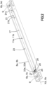
- an installation 1 comprising a closing, concealing or solar protection device according to an embodiment of the invention.
- This installation 1 installed in a building, not shown, comprises an opening, not shown, in which a window or a door, not shown, is arranged.
- This installation 1 is equipped with a screen 2 belonging to the closing, concealing or solar protection device 3, in particular a motorized blind.
- the screen 2 is configured to conceal, at least partially, the opening made in a wall of the building.
- the closing, concealing or sun protection device 3 is hereinafter called the “concealing device”.
- the concealing device 3 comprises the screen 2.
- the screen 2 can be formed, for example, from a pleated or honeycombed canvas or from slats which can be adjusted.
- the screen 2 comprises a first end 2a, in particular an upper end, and a second end 2b, in particular a lower end, the second end 2b being opposite the first end 2a.
- the occulting device 3 comprises a first movable bar 8a, in particular an upper movable bar.
- the first end 2a of the screen 2 is connected to the first movable bar 8a.
- the occulting device 3 further comprises a second movable bar 8b, in particular a lower movable bar.
- the second end 2b of the screen 2 is connected to the second movable bar 8b.
- the second movable bar 8b is identical to the first movable bar 8a. This is why the Figure 2 represents indifferently the first movable bar 8a or the second movable bar 8b and the references 8a and 8b are used jointly on this Figure 2 .
- the screen 13 is arranged, in other words is configured to be deployed, between the first and second movable bars 8a, 8b. Depending on the relative position of the first and second movable bars 8a, 8b, the screen 2 is more or less deployed.
- the first movable bar 8a is shown at figures 1 And 2 with a central opening 23, through which a first electromechanical actuator 11a is visible.
- This central opening 23 makes it easier to read the figures 1 And 2 and, in particular, to facilitate the understanding of the integration of the first electromechanical actuator 11a inside the first movable bar 8a.
- the first movable bar 8a may, consequently, be devoid of this central opening 23, so as to improve the aesthetic appearance of the occulting device 3.
- the occulting device 3 comprises a motorized drive device 5.
- the motorized drive device 5 is configured to drive in movement, in other words drives in movement, the screen 2.
- the motorized drive device 5 comprises at least the first electromechanical actuator 11a.
- the first electromechanical actuator 11a is housed, otherwise is configured to be housed, inside the first movable bar 8a, in particular in an assembled configuration of the occulting device 3.
- the first actuator electromechanical 11a is configured to drive in movement, in other words drives in movement, the first movable bar 8a.
- the motorized drive device 5 further comprises a second electromechanical actuator 11b.
- the second electromechanical actuator 11b is not visible in the Figure 1 .
- the second electromechanical actuator 11b is housed inside the second movable bar 8b.
- the second electromechanical actuator 11b is configured to drive in displacement, in other words drives in displacement, the second movable bar 8b.
- the second electromechanical actuator 11b is identical to the first electromechanical actuator 11a.
- the figures 2 to 6 represent indifferently the first electromechanical actuator 11a or the second electromechanical actuator 11b, since these are identical. This is why the references 11a and 11b are used jointly on these figures 2 to 6 .
- the occulting device 3 comprises a first cord 4a, a second cord 4b, a first drive arrangement 6a and a second drive arrangement 6b.
- the first drive arrangement 6a is configured to cooperate, in other words cooperates, with the first cord 4a.
- the second drive arrangement 6b is configured to cooperate, in other words cooperates, with the second cord 4b.
- the first electromechanical actuator 11a is configured to drive in movement, in other words drives in movement, the first movable bar 8a along the first and second cords 4a, 4b.
- the occulting device 3 further comprises a third cord 4c, a fourth cord 4d, a third drive arrangement 6c and a fourth drive arrangement 6d.
- the third and fourth drive arrangements 6c, 6d are not visible at the Figure 1 .
- the third drive arrangement 6c is configured to cooperate, i.e. cooperates, with the third cord 4c.
- the fourth drive arrangement 6d is configured to cooperate, i.e. cooperates, with the fourth cord 4d.
- the first, second, third and fourth cords 4a, 4b, 4c, 4d may also be referred to as the first, second, third and fourth guide or suspension cords.
- the third and fourth drive arrangements 6c, 6d are respectively identical to the first and second drive arrangements 6a, 6b.
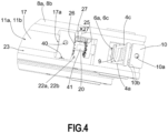
- figures 2 , 4 And 5 represent indifferently the first and second drive arrangements 6a, 6b or the third and fourth drive arrangements 6c, 6d, since these are identical.
- each of the first and second drive arrangements 6a, 6b, respectively each of the third and fourth drive arrangements 6c, 6d comprises at least one pulley 9. Furthermore, each of the first and second cords 4a, 4b, respectively each of the third and fourth cords 4c, 4d, is wound around the pulley 9 of one of the first and second drive arrangements 6a, 6b, respectively of one of the third and fourth drive arrangements 6c, 6d.
- the pulley 9 of each of the first and second drive arrangements 6a, 6b, respectively of each of the third and fourth drive arrangements 6c, 6d is a smooth pulley.
- the first and second cords 4a, 4b, respectively the third and fourth cords 4c, 4d are smooth cords.
- an adhesion torque transmission is implemented between the first and second cords 4a, 4b and the pulleys 9 of the first and second drive arrangements 6a, 6b, to move the first movable bar 8a. Furthermore, an adhesion torque transmission is implemented between the third and fourth cords 4c, 4d and the pulleys 9 of the third and fourth drive arrangements 6c, 6d, to move the second movable bar 8b.
- first and second cords 4a, 4b, respectively the third and fourth cords 4c, 4d may be configured to slide, in other words slide, around the pulleys 9 of each of the first and second drive arrangements 6a, 6b, respectively of each of the third and fourth drive arrangements 6c, 6d, in particular to allow manual movement of the first movable bar 8a, respectively the second movable bar 8b, by the user.
- the sliding of the first and second cords 4a, 4b around the pulleys 9 of each of the first and second drive arrangements 6a, 6b is dependent, in particular, on the tension of the first and second cords 4a, 4b and on the number of winding turns of each of the first and second cords 4a, 4b around the pulley 9 of one of the first and second drive arrangements 6a, 6b.
- the sliding of the third and fourth cords 4c, 4d around the pulleys 9 of each of the third and fourth drive arrangements 6c, 6d is dependent, in particular, on the tension of the third and fourth cords 4c, 4d and on the number of winding turns of each of the third and fourth cords 4c, 4d around the pulley 9 of one of the third and fourth drive arrangements 6c, 6d.
- the winding of each of the first and second cords 4a, 4b, respectively of each of the third and fourth cords 4c, 4d, around the pulley 9 of one of the first and second drive arrangements 6a, 6b, respectively of one of the third and fourth drive arrangements 6c, 6d is implemented with a single turn.
- the winding of each of the first and second cords 4a, 4b, respectively of each of the third and fourth cords 4c, 4d, around the pulley 9 of one of the first and second drive arrangements 6a, 6b, respectively of one of the third and fourth drive arrangements 6c, 6d is implemented with several turns.
- the first electromechanical actuator 11a is configured to drive in rotation, in other words drives in rotation, the pulley 9 of each of the first and second drive arrangements 6a, 6b, respectively the pulley 9 of each of the third and fourth drive arrangements 6c, 6d.
- each of the first and second drive arrangements 6a, 6b is arranged near one of the ends of the first movable bar 8a. Furthermore, each of the third and fourth drive arrangements 6c, 6d is arranged near one of the ends of the second movable bar 8b.
- first and second cords 4a, 4b, as well as the third and fourth cords 4c, 4d, in particular their ends, are fixed to a window or door structure or to a wall of the building, in particular by means of holding elements 10.
- the concealment device 3 may be devoid of a housing, in other words of a rail, arranged in the upper part or above the opening.
- first and third cords 4a, 4c, respectively the second and fourth cords 4b, 4d are formed from different cord strands.
- first and third cords 4a, 4c, respectively the second and fourth cords 4b, 4d are held, at the upper or lower part of the opening of the window or door, by pinching between two walls 10b of one of the holding elements 10.
- the first and third cords 4a, 4c, respectively the second and fourth cords 4b, 4d may be formed from the same strand of cord.
- the first and third cords 4a, 4c, respectively the second and fourth cords 4b, 4d may be held, at the upper part or at the lower part of the opening of the window or the door, by winding around one of the holding elements 10.
- the holding elements 10 are configured to be fixed, i.e. are fixed, to the window or door structure or to the building wall by means of fixing screws, not shown.
- the fixing screws pass through through holes 10a provided in the holding elements 10 and are screwed either into dowels, not shown, housed in the window or door structure or in the building wall or directly into the window or door structure or in the building wall.
- the transmission of torque by adhesion between the first and second cords 4a, 4b and the pulleys 9 of the first and second drive arrangements 6a, 6b for moving the first movable bar 8a is a function, on the one hand, of the tension of the first and second cords 4a, 4b relative to the window or door structure or the wall of the building, obtained with the holding elements 10, and, on the other hand, of the number of turns of winding of each of the first and second cords 4a, 4b around the pulley 9 of one of the first and second drive arrangements 6a, 6b.
- the transmission of torque by adhesion between the third and fourth cords 4c, 4d and the pulleys 9 of the third and fourth drive arrangements 6c, 6d for moving the second movable bar 8b is a function, on the one hand, of the tension of the third and fourth cords 4c, 4d relative to the window or door structure or the wall of the building, obtained with the holding elements 10, and, on the other hand, of the number of turns of winding of each of the third and fourth cords 4c, 4d around the pulley 9 of one of the third and fourth drive arrangements 6c, 6d.
- the drive device 5 is thus configured to drive in movement, in other words drives in movement, in particular in a vertical direction, the first and second movable bars 8a, 8b of the occulting device 3, along the first, second, third and fourth cords 4a, 4b, 4c, 4d, by means of the first and second electromechanical actuators 11a, 11b.
- first and second movable bars 8a, 8b are parallel to each other, in particular in the assembled configuration of the occulting device 3.
- the motorized drive device 5 and, more particularly, each of the first and second electromechanical actuators 11a, 11b, is controlled by a control unit.
- the control unit may be, for example, a local control unit 12 or a central control unit 13.
- the local control unit 12 can be connected, by wired or wireless connection, with the central control unit 13.
- the central control unit 13 can control the local control unit 12, as well as other similar local control units distributed throughout the building.
- the motorized drive device 5 is preferably configured to execute the movement commands, in particular deployment or retraction, of the screen 2, which can be issued, in particular, by the local control unit 12 or by the central control unit 13.
- the installation 1 comprises either the local control unit 12, or the central control unit 13, or the local control unit 12 and the central control unit 13.
- the motorized drive device 5 including the first and second electromechanical actuators 11a, 11b, belonging to the installation 1 and, more particularly, to the occultation device 3 illustrated in the Figure 1 .
- the first electromechanical actuator 11a respectively the second electromechanical actuator 11b, comprises an electric motor 16, represented by a dotted line frame at Figure 3
- the electric motor 16 of the first electromechanical actuator 11a may be referred to as the first electric motor and the electric motor 16 of the second electromechanical actuator 11b may be referred to as the second electric motor.
- the electric motor 16 of the first electromechanical actuator 11a comprises a rotor and a stator, not shown, positioned coaxially around a first axis of rotation Xa, respectively of a second axis of rotation Xb, which is also the axis of rotation of the pulleys 9 of the first and second drive arrangements 6a, 6b, respectively of the third and fourth drive arrangements 6c, 6d, in particular in the assembled configuration of the occulting device 3.
- the electric motor 16 of the first electromechanical actuator 11a may be of the brushless type with electronic commutation, also called “BLDC” (acronym for the English term BrushLess Direct Current) or “synchronous with permanent magnets”, or of the direct current type.
- BLDC brushless type with electronic commutation
- synchronous with permanent magnets or of the direct current type.
- Means for controlling the first electromechanical actuator 11a, respectively the second electromechanical actuator 11b, allowing the movement of the screen 2 comprise at least one control unit 15, in particular an electronic control unit, represented by a dotted line frame at Figure 3 .
- the first electromechanical actuator 11a respectively the second electromechanical actuator 11b, further comprises the control unit 15.
- the control unit 15 of the first electromechanical actuator 11a can be called the first control unit and the control unit 15 of the second electromechanical actuator 11b can be called the second control unit.
- the control unit 15 of the first electromechanical actuator 11a, respectively of the second electromechanical actuator 11b is capable of putting into operation the electric motor 16 of the first electromechanical actuator 11a, respectively of the second electromechanical actuator 11b, and, in particular, of enabling the supply of electrical energy to the electric motor 16 of the first electromechanical actuator 11a, respectively of the second electromechanical actuator 11b.
- the first control unit 15 controls, in particular, the first electric motor 16, so as to raise or lower the first movable bar 8a and, consequently, the upper part of the screen 2
- the second control unit 15 controls, in particular, the second electric motor 16, so as to raise or lower the second movable bar 8b and, consequently, the lower part of the screen 2.
- the control unit 15 of the first electromechanical actuator 11a, respectively of the second electromechanical actuator 11b, comprises hardware and/or software means.
- the hardware means of the control unit 15 of the first electromechanical actuator 11a, respectively of the second electromechanical actuator 11b comprise at least one microcontroller, not shown.
- control unit 15 of the first electromechanical actuator 11a further comprises a first communication module, not shown, in particular for receiving orders.
- control the control orders being issued by an order transmitter, such as the local control unit 12 or the central control unit 13, these orders being intended to control the first electromechanical actuator 11a, respectively the second electromechanical actuator 11b.
- the first communication module is of the wireless type.
- the first communication module is configured to receive radio control orders.
- the first communication module may allow the reception of control orders transmitted by wired means.
- control unit 15, the local control unit 12 and/or the central control unit 13 can be in communication with a weather station, arranged inside the building or remote outside the building, including, in particular, one or more sensors which can be configured to determine, for example, a temperature, a brightness, or even a wind speed, in the case where the weather station is remote outside the building.
- control unit 15, the local control unit 12 and/or the central control unit 13 can also be in communication with a server 28, so as to control the motorized drive device 5 and, more particularly, the first and second electromechanical actuators 11a, 11b, according to data made available remotely via a communication network, in particular an Internet network which can be connected to the server 28.
- a communication network in particular an Internet network which can be connected to the server 28.
- the control unit 15 can be controlled from the local control unit 12 or the central control unit 13.
- the local control unit 12 or the central control unit 13 is provided with a control keyboard.
- the control keyboard comprises one or more selection elements 14 and, optionally, one or more display elements 34.
- the selection elements may comprise push buttons and/or touch keys.
- the display elements may comprise light-emitting diodes and/or a display, for example LCD (acronym for the English term “Liquid Crystal Display”) or TFT (acronym for the English term “Thin Film Transistor”).
- LCD liquid Crystal Display
- TFT thin Film Transistor
- the selection and display elements may also be implemented using a touch screen.
- the local control unit 12 or the central control unit 13 further comprises at least one second communication module 36.
- the second communication module 36 is configured to transmit, in other words emits, control orders, in particular by wireless means, by example radioelectric, or by wired means.
- the second communication module 36 can also be configured to receive, in other words receives, control orders, in particular via the same means.
- the second communication module 36 of the local control unit 12 or of the central control unit 13 is configured to communicate, in other words communicates, with the first communication module of the control unit 15.
- the second communication module 36 of the local control unit 12 or of the central control unit 13 exchanges control commands with the first communication module of the control unit 15, either unidirectionally or bidirectionally.
- the local control unit 12 is a control point, which may be fixed or mobile.
- a fixed control point may be a control box intended to be fixed on a facade of a wall of the building or on a face of a fixed frame of a window or a door.
- a mobile control point may be a remote control, a smartphone or a tablet.
- the local control unit 12 or the central control unit 13 further comprises a controller 35.
- the motorized drive device 5, in particular the control unit 15 of each of the first and second electromechanical actuators 11a, 11b, is preferably configured to execute movement control orders, in particular for folding and deployment, of the screen 2. These control orders can be issued, in particular, by the local control unit 12 or by the central control unit 13.
- the motorized drive device 5 can be controlled by the user, for example by receiving a control command corresponding to pressing the or one of the selection elements 14 of the local control unit 12 or of the central control unit 13.
- the motorized drive device 5 can also be controlled automatically, for example by receiving a control command corresponding to at least one signal from at least one sensor, not shown, and/or a signal from a clock, not shown, of the control unit 15, in particular the microcontroller.
- the sensor and/or the clock can be integrated, alternatively, into the local control unit 12 or the central control unit 13.
- the first electromechanical actuator 11a respectively the second electromechanical actuator 11b, further comprises a casing 17, in particular a tubular casing.
- the casing 17 of the first electromechanical actuator 11a can be called the first casing and the casing 17 of the second electromechanical actuator 11b can be called the second casing.
- the electric motor 16 of the first electromechanical actuator 11a, respectively of the second electromechanical actuator 11b is mounted inside the casing 17 of the first electromechanical actuator 11a, respectively of the second electromechanical actuator 11b, in particular in the assembled configuration of the first electromechanical actuator 11a, respectively of the second electromechanical actuator 11b.
- the casing 17 of the first electromechanical actuator 11a, respectively of the second electromechanical actuator 11b, comprises a first end 17a and a second end 17b, the second end 17b being opposite the first end 17a.
- the casing 17 of the first electromechanical actuator 11a, respectively of the second electromechanical actuator 11b is hollow, of cylindrical shape, in particular of revolution around the first axis of rotation Xa, respectively of the second axis of rotation Xb, and is open at each of its ends 17a, 17b.
- the casing 17 of the first electromechanical actuator 11a, respectively of the second electromechanical actuator 11b is a tube having a circular section.
- the casing 17 is parallelepipedal in shape.
- the casing 17 is made of a metallic material.
- the material of the casing is not limiting and can be different. It can be, in particular, a plastic material.
- the first electromechanical actuator 11a respectively the second electromechanical actuator 11b, further comprises a battery 18, represented by a frame in dotted lines at Figure 3 .
- the battery 18 of the first electromechanical actuator 11a can be called the first battery and the battery 18 of the second electromechanical actuator 11b can be called the second battery.
- the battery 18 of the first electromechanical actuator 11a is configured to supply electrical energy, in other words supplies electrical energy, to the electric motor 16, as well as to the control unit 15, of the first electromechanical actuator 11a.
- the battery 18 of the second electromechanical actuator 11b is configured to supply electrical energy, in other words supplies electrical energy, to the electric motor 16, as well as to the control unit 15, of the second electromechanical actuator 11b.
- the battery 18 of the first electromechanical actuator 11a, respectively of the second electromechanical actuator 11b is mounted inside the casing 17 of the first electromechanical actuator 11a, respectively of the second electromechanical actuator 11b, in particular in the assembled configuration of the first electromechanical actuator 11a, respectively of the second electromechanical actuator 11b.
- the battery 18 of the first electromechanical actuator 11a, respectively of the second electromechanical actuator 11b is mounted inside the first movable bar 8a, respectively of the second movable bar 8b, while being arranged outside the casing 17 of the electromechanical actuator 11a, 11b in question, in particular in the assembled configuration of the occulting device 3.
- the battery 18 of the first electromechanical actuator 11a, respectively of the second electromechanical actuator 11b is electrically connected to the control unit 15 of the first electromechanical actuator 11a, respectively of the second electromechanical actuator 11b, by means of an electrical connection formed from rotating electrical tracks, around the first axis of rotation Xa, respectively of the second axis of rotation Xb.
- the control unit 15 of the first electromechanical actuator 11a, respectively of the second electromechanical actuator 11b comprises charging elements configured to charge the battery 18 of the first electromechanical actuator 11a, respectively of the second electromechanical actuator 11b, from the electrical energy supplied by an external electrical energy supply source, not shown.
- the charging elements comprise, at least, an electrical connector 24, in the case where the battery 18 of the first electromechanical actuator 11a, respectively of the second electromechanical actuator 11b, is of the rechargeable type, as illustrated in Figure 6
- the external electrical power supply source is configured to be electrically connected to the electrical connector 24, via an electrical power cable, not shown.
- the external electrical power supply source is a charger, which can be plugged into a wall electrical outlet, so as to recharge the battery 18 of the first electromechanical actuator 11a, respectively of the second electromechanical actuator 11b, from a mains electrical power supply network.
- the external electrical power source may be an auxiliary battery or a photovoltaic panel.
- the first electromechanical actuator 11a respectively the second electromechanical actuator 11b, comprises a first end 11c and a second end 11d, the second end 11d being opposite the first end 11c.
- the first electromechanical actuator 11a respectively the second electromechanical actuator 11b, further comprises a coupling support 21.
- the coupling support 21 of the first electromechanical actuator 11a can be called the first coupling support and the coupling support 21 of the second electromechanical actuator 11b can be called the second coupling support.
- the coupling support 21 of the first electromechanical actuator 11a, respectively of the second electromechanical actuator 11b, is arranged at the first end 11c of the first electromechanical actuator 11a, respectively of the second electromechanical actuator 11b.
- the first end 11c of the first electromechanical actuator 11a, respectively of the second electromechanical actuator 11b is defined by its coupling support 21.
- the coupling support 21 of the first electromechanical actuator 11a, respectively of the second electromechanical actuator 11b, is movable in rotation, around the first axis of rotation Xa, respectively of the second axis of rotation Xb, inside the first movable bar 8a, respectively of the second movable bar 8b.
- the first electromechanical actuator 11a respectively the second electromechanical actuator 11b, further comprises a single output shaft 20, i.e. a single output shaft 20.
- the output shaft 20 of the first electromechanical actuator 11a can be called the first output shaft and the output shaft 20 of the second electromechanical actuator 11b can be called the second output shaft.
- the output shaft 20 of the first electromechanical actuator 11a, respectively of the second electromechanical actuator 11b, is arranged at the second end 11d of the first electromechanical actuator 11a, respectively of the second electromechanical actuator 11b.
- the second end 11d of the first electromechanical actuator 11a, respectively of the second electromechanical actuator 11b, is defined by its output shaft 20.
- the output shaft 20 of the first electromechanical actuator 11a, respectively of the second electromechanical actuator 11b, is rotatable, around the first axis of rotation Xa, respectively of the second axis of rotation Xb, inside the first movable bar 8a, respectively of the second movable bar 8b.
- the concealing device 3 makes it possible to simplify the integration of the first electromechanical actuator 11a inside the first movable bar 8a while minimizing the cost of obtaining the first electromechanical actuator 11a. Furthermore, the concealing device 3 makes it possible to simplify the integration of the second electromechanical actuator 11b inside the second movable bar 8b, while minimizing the cost of obtaining the second electromechanical actuator 11b.
- the first movable bar 8a is configured to be driven in displacement by means of the first electromechanical actuator 11a with a single output, respectively the second electromechanical actuator 11b with a single output, and without the latter being crossed by a drive shaft.
- the coupling support 21 and the output shaft 20 of the first electromechanical actuator 11a, respectively of the second electromechanical actuator 11b are respectively rotatable inside the first movable bar 8a, respectively of the second movable bar 8b, so that the first and second ends 11c, 11d of the first electromechanical actuator 11a, respectively of the second electromechanical actuator 11b, are driven in rotation inside the first movable bar 8a, respectively of the second movable bar 8b, when moving the first movable bar 8a, respectively of the second movable bar 8b.
- the coupling support 21 and the output shaft 20 of the first electromechanical actuator 11a, respectively of the second electromechanical actuator 11b are not stationary relative to the first movable bar 8a, respectively relative to the second movable bar 8b, during the movement of the first movable bar 8a, respectively of the second movable bar 8b.
- neither the coupling support 21 nor the output shaft 20 of the first electromechanical actuator 11a, respectively of the second electromechanical actuator 11b, is fixed, in other words is not immobile, relative to the first movable bar 8a, respectively relative to the second movable bar 8b, during the movement of the first movable bar 8a, respectively of the second movable bar 8b.
- the occulting device 3 equipped with the first and second movable bars 8a, 8b and fixed to the window or door structure or to the wall of the building, by means of the first, second, third and fourth cords 4a, 4b, 4c, 4d, is motorized by the first and second electromechanical actuators 11a, 11b which each have a single output.
- first movable bar 8a can be moved manually along the first and second cords 4a, 4b, respectively the third and fourth cords 4c, 4d.
- first and second cords 4a, 4b respectively the third and fourth cords 4c, 4d slide, around the pulleys 9 of each of the first and second drive arrangements 6a, 6b, respectively of each of the third and fourth drive arrangements 6c, 6d, during the movement of the first movable bar 8a, respectively the second movable bar 8b, exercised by hand by a user.
- the coupling support 21 of the first electromechanical actuator 11a, respectively of the second electromechanical actuator 11b is driven in rotation, in other words is configured to be driven in rotation, in the opposite direction to the direction of rotation of the output shaft 20 of the first electromechanical actuator 11a, respectively of the second electromechanical actuator 11b, during the movement of the first movable bar 8a, respectively of the second movable bar 8b.
- the output shaft 20 of the first electromechanical actuator 11a is driven in rotation by the electric motor 16 of the first electromechanical actuator 11a in a first direction of rotation, while the coupling support 21 of the first electromechanical actuator 11a is driven in rotation in a second direction of rotation, opposite to the first direction of rotation, by a counter-reaction to the rotational drive of the output shaft 20 of the first electromechanical actuator 11a.
- the output shaft 20 of the second electromechanical actuator 11b is rotated by the electric motor 16 of the second electromechanical actuator 11b in a first direction of rotation, while the coupling support 21 of the second electromechanical actuator 11b is rotated in a second direction of rotation, opposite to the first direction of rotation, by a counter-reaction to the rotational drive of the output shaft 20 of the second electromechanical actuator 11b.
- the coupling support 21 of the first electromechanical actuator 11a is rotationally fixed to the stator of the electric motor 16 of the first electromechanical actuator 11a, respectively of the second electromechanical actuator 11b.
- the stator of the electric motor 16 of the first electromechanical actuator 11a is rotationally fixed to the casing 17 of the first electromechanical actuator 11a, respectively of the second electromechanical actuator 11b.
- the coupling support 21 of the first electromechanical actuator 11a, respectively of the second electromechanical actuator 11b makes it possible to take up the forces exerted by the first electromechanical actuator 11a, respectively of the second electromechanical actuator 11b, in particular the weight of the first electromechanical actuator 11a, respectively of the second electromechanical actuator 11b, and to ensure the take-up of these forces by the first movable bar 8a, respectively the second movable bar 8b.
- the pulley 9 of the first drive arrangement 6a, respectively of the third drive arrangement 6c is fitted, in other words is configured to be fitted, on the output shaft 20 of the first electromechanical actuator 11a, respectively of the second electromechanical actuator 11b, in particular in the assembled configuration of the occulting device 3.
- the pulley 9 of the first drive arrangement 6a, respectively of the third drive arrangement 6c is connected, in other words is configured to be connected, to the output shaft 20 of the first electromechanical actuator 11a, respectively of the second electromechanical actuator 11b.
- the output shaft 20 of the first electromechanical actuator 11a is configured to drive in rotation, in other words drives in rotation, the pulley 9 of the first drive arrangement 6a, respectively of the third drive arrangement 6c.
- the output shaft 20 of the first electromechanical actuator 11a, respectively of the second electromechanical actuator 11b is arranged inside the first movable bar 8a, respectively of the second movable bar 8b, and at least partly outside the casing 17 of the first electromechanical actuator 11a, respectively of the second electromechanical actuator 11b.
- the output shaft 20 projects relative to the casing 17 of the first electromechanical actuator 11a, respectively of the second electromechanical actuator 11b, in particular relative to the second end 17b of the casing 17.
- the coupling support 21 of the first electromechanical actuator 11a comprises a base 21a, a cover 21b and a coupling shaft 21c.
- the cover 21b is assembled, in other words is configured to be assembled, on the base 21a, in particular in the assembled configuration of the first electromechanical actuator 11a, respectively of the second electromechanical actuator 11b.
- This cover 21b is omitted at the Figure 6 .
- the pulley 9 of the second drive arrangement 6b, respectively of the fourth drive arrangement 6d is fitted, in other words is configured to be fitted, on the coupling shaft 21c of the first electromechanical actuator 11a, respectively of the second electromechanical actuator 11b, in particular in the assembled configuration of the occulting device 3.
- the pulley 9 of the second drive arrangement 6b, respectively of the fourth drive arrangement 6d is connected, in other words is configured to be connected, to the coupling shaft 21c of the first electromechanical actuator 11a, respectively of the second electromechanical actuator 11b.
- the coupling shaft 21c of the first electromechanical actuator 11a, respectively of the second electromechanical actuator 11b is configured to drive in rotation, in other words drives in rotation, the pulley 9 of the second drive arrangement 6b, respectively of the fourth drive arrangement 6d.
- the coupling support 21 projects at the level of the first end 11c of the first electromechanical actuator 11a, respectively of the second electromechanical actuator 11b, relative to the casing 17 of the first electromechanical actuator 11a, respectively of the second electromechanical actuator 11b.
- the coupling shaft 21c of the first electromechanical actuator 11a, respectively of the second electromechanical actuator 11b is arranged inside the first movable bar 8a, respectively of the second movable bar 8b, and at least partly outside the casing 17 of the first electromechanical actuator 11a, respectively of the second electromechanical actuator 11b.
- the coupling shaft 21c projects relative to the casing 17 of the first electromechanical actuator 11a, respectively of the second electromechanical actuator 11b, in particular relative to the first end 17a of the casing 17.
- the coupling support 21 of the first electromechanical actuator 11a, respectively of the second electromechanical actuator 11b closes, in other words is configured to close, one of the ends of the casing 17 of the first electromechanical actuator 11a, respectively of the second electromechanical actuator 11b, in particular in the assembled configuration of the first electromechanical actuator 11a, respectively of the second electromechanical actuator 11b.
- the coupling support 21 of the first electromechanical actuator 11a, respectively of the second electromechanical actuator 11b is fixed, in other words is configured to be fixed, to the casing 17 of the first electromechanical actuator 11a, respectively of the second electromechanical actuator 11b, by means of fixing elements, in particular in the assembled configuration of the first electromechanical actuator 11a, respectively of the second electromechanical actuator 11b.
- the fixing elements are fixing screws, not shown, and notches 31, 32, in other words notches and teeth or crenellations, of the casing 17 and the coupling support 21 nested within each other.
- the fixing screws pass through through holes 35 provided in the casing 17, only one of which is visible at figures 3 And 6 , and are screwed into screw holes, not shown, of the coupling support 21.
- the elements for fixing the casing 17 and the coupling support 21 to each other may be bosses, elastic snap-fastening elements or a combination of different fixing elements.
- the coupling support 21 of the first electromechanical actuator 11a comprises a first part, not shown, and a second part 21d.
- the first part of the coupling support 21 of the first electromechanical actuator 11a, respectively of the second electromechanical actuator 11b is configured to cooperate, in other words cooperates, with the casing 17 of the first electromechanical actuator 11a, respectively of the second electromechanical actuator 11b, in particular in the assembled configuration of the first electromechanical actuator 11a, respectively of the second electromechanical actuator 11b.
- the second part 21d of the coupling support 21 of the first electromechanical actuator 11a, respectively of the second electromechanical actuator 11b is configured to cooperate, in other words cooperates, with the second drive arrangement 6b, respectively the fourth drive arrangement 6d, in particular in the assembled configuration of the occulting device 3.
- the coupling support 21 of the first electromechanical actuator 11a, respectively of the second electromechanical actuator 11b further comprises a stop 33.
- the stop 33 of the first electromechanical actuator 11a, respectively of the second electromechanical actuator 11b bears, in other words is configured to bear, against the casing 17 of the first electromechanical actuator 11a, respectively of the second electromechanical actuator 11b, at the second end 17b of the casing 17, in particular in the assembled configuration of the first electromechanical actuator 11a, respectively of the second electromechanical actuator 11b.
- the stop 33 makes it possible to limit the sinking of the first part of the coupling support 21 into the casing 17 of the first electromechanical actuator 11a, respectively of the second electromechanical actuator 11b, in the direction of the first axis of rotation Xa, respectively of the second axis of rotation Xb.
- the stop 33 comprises a shoulder. More particularly, it is produced in the form of a collar, in particular of cylindrical shape and with a rectilinear generatrix.
- stop 33 may delimit the first and second parts of the coupling support 21 relative to each other.
- the coupling support 21 of the first electromechanical actuator 11a, respectively of the second electromechanical actuator 11b is of cylindrical shape.
- the casing 17 and the coupling support 21 of the first electromechanical actuator 11a, respectively of the second electromechanical actuator 11b have the same external diameter ⁇ .
- the motorized drive device 5 further comprises a first synchronization mechanism 22a.
- the first synchronization mechanism 22a is arranged, in other words is configured to be arranged, in the vicinity of the second end 11d of the first electromechanical actuator 11a, in particular in the assembled configuration of the occulting device 3.
- the motorized drive device 5 further comprises a second synchronization mechanism 22b.
- the second synchronization mechanism 22b is not visible in the Figure 1 .
- the second synchronization mechanism 22b is arranged, in other words is configured to be arranged, in the vicinity of the second end 11d of the second electromechanical actuator 11b, in particular in the assembled configuration of the occultation device 3.
- the second synchronization mechanism 22b is identical to the first synchronization mechanism 22a.
- figures 2 And 4 represent indifferently the first synchronization mechanism 22a or the second synchronization mechanism 22b, since these are identical.
- the first synchronization mechanism 22a comprises a first pinion 25, a second pinion 26 and a third pinion 27.
- the first pinion 25 of the first synchronization mechanism 22a, respectively of the second synchronization mechanism 22b, is fixed, in other words is configured to be fixed, on the output shaft 20 of the first electromechanical actuator 11a, respectively of the second electromechanical actuator 11b, in particular in the assembled configuration of the occulting device 3.
- the second pinion 26 of the first synchronization mechanism 22a, respectively of the second synchronization mechanism 22b, is fixed, in other words is configured to be fixed, on the casing 17 of the first electromechanical actuator 11a, respectively of the second electromechanical actuator 11b, in particular in the assembled configuration of the occulting device 3.
- the third pinion 27 of the first synchronization mechanism 22a, respectively of the second synchronization mechanism 22b, is fixed, in other words is configured to be fixed, on the casing 17 of the first electromechanical actuator 11a, respectively of the second electromechanical actuator 11b, in particular in the assembled configuration of the occulting device 3.
- the first synchronization mechanism 22a makes it possible to ensure that the pulley 9 of the first drive arrangement 6a achieves the same angular rotation as the pulley 9 of the second drive arrangement 6b in particular in opposite directions to each other and at the same rotational speed, when moving the first movable bar 8a. Furthermore, the second synchronization mechanism 22b ensures that the pulley 9 of the third drive arrangement 6c performs the same angular rotation as the pulley 9 of the fourth drive arrangement 6d, in particular in opposite directions to each other and at the same rotational speed, when moving the second movable bar 8b.
- first synchronization mechanism 22a respectively the second synchronization mechanism 22b, makes it possible to prevent rotation of the first electromechanical actuator 11a, respectively of the second electromechanical actuator 11b, on itself.
- the first synchronization mechanism 22a makes it possible to ensure that the first movable bar 8a, respectively the second movable bar 8b, are kept in a horizontal position relative to the first and second cords 4a, 4b, respectively the third and fourth cords 4c, 4d.
- the first synchronization mechanism 22a and the second synchronization mechanism 22b make it possible to guarantee parallelism between the first movable bar 8a and the second movable bar 8b.
- first and second pinions 25, 26 are so-called “flat” pinions and the third pinion 27 is a straight-toothed pinion.
- the meshing between the first pinion 25 and the third pinion 27, respectively between the second pinion 26 and the third pinion 27, is said to be “facial”.
- the fixing of the first pinion 25 of the first synchronization mechanism 22a, respectively of the second synchronization mechanism 22b, on the output shaft 20 of the first electromechanical actuator 11a, respectively of the second electromechanical actuator 11b is implemented by fitting.
- the first pinion 25 of the first synchronization mechanism 22a, respectively of the second synchronization mechanism 22b is locked in rotation relative to the output shaft 20 of the first electromechanical actuator 11a, respectively of the second electromechanical actuator 11b, in particular by means of a flat 41 provided on the output shaft 20 of the first electromechanical actuator 11a, respectively of the second electromechanical actuator 11b.
- the fixing of the second pinion 26 of the first synchronization mechanism 22a, respectively of the second synchronization mechanism 22b, on the casing 17 of the first electromechanical actuator 11a, respectively of the second electromechanical actuator 11b is implemented by fixing elements, not shown, which may be, for example, fixing screws.
- the fixing screws pass through through holes 40 provided in the second pinion 26, two of which are visible in figures 3 And 4 , and are screwed into screw holes, not shown, of the casing 17.
- the third pinion 27 of the first synchronization mechanism 22a, respectively of the second synchronization mechanism 22b is mounted free to rotate, in other words is configured to be mounted free to rotate, around an axis of rotation X27, relative to the first movable bar 8a, respectively relative to the second movable bar 8b, in particular in the assembled configuration of the occulting device 3.
- the third pinion 27 is a reference element for the first and second pinions 25, 26.
- the third pinion 27 of the first synchronizing mechanism 22a ensures that the pulley 9 of the first drive arrangement 6a performs the same angular rotation as the pulley 9 of the second drive arrangement 6b, in particular in opposite directions to each other and at the same rotational speed, when moving the first movable bar 8a. Furthermore, the third pinion 27 of the second synchronizing mechanism 22b ensures that the pulley 9 of the third drive arrangement 6c performs the same angular rotation as the pulley 9 of the fourth drive arrangement 6d, in particular in opposite directions to each other and at the same rotational speed, when moving the second movable bar 8b.
- the control unit 15 of the first electromechanical actuator 11a comprises two electronic cards 15a, 15b.
- a first electronic card 15a of the control unit 15, represented by a frame in dotted lines at Figure 3 , of the first electromechanical actuator 11a, respectively of the second electromechanical actuator 11b, is configured to control the electric motor 16 of the first electromechanical actuator 11a, respectively of the second electromechanical actuator 11b.
- a second electronic card 15b of the control unit 15 of the first electromechanical actuator 11a, respectively of the second electromechanical actuator 11b is configured to, in particular, access parameterization and/or configuration functions of the first electromechanical actuator 11a, respectively of the second electromechanical actuator 11b, by means of selection and, possibly, display devices, not shown.
- the second electronic card 15b of the control unit 15 of the first electromechanical actuator 11a, respectively of the second electromechanical actuator 11b is configured to allow the recharging of the battery 18 of the first electromechanical actuator 11a, respectively of the second electromechanical actuator 11b.
- the first electronic card 15a of the control unit 15 of the first electromechanical actuator 11a, respectively of the second electromechanical actuator 11b is mounted inside the casing 17 of the first electromechanical actuator 11a, respectively of the second electromechanical actuator 11b, in particular in the assembled configuration of the first electromechanical actuator 11a, respectively of the second electromechanical actuator 11b.
- the second electronic card 15b of the control unit 15 of the first electromechanical actuator 11a, respectively of the second electromechanical actuator 11b is mounted inside the coupling support 21 of the first electromechanical actuator 11a, respectively of the second electromechanical actuator 11b, in particular in the assembled configuration of the first electromechanical actuator 11a, respectively of the second electromechanical actuator 11b.
- the second electronic card 15b of the control unit 15 of the first electromechanical actuator 11a is mounted between the base 21a and the cover 21b of the coupling support 21 of the first electromechanical actuator 11a, respectively of the second electromechanical actuator 11b.
- control unit 15 of the first electromechanical actuator 11a comprises a single electronic card.
- the single electronic card of the control unit 15 of the first electromechanical actuator 11a, respectively of the second electromechanical actuator 11b, is mounted inside the casing 17 or the coupling support 21 of the first electromechanical actuator 11a, respectively of the second electromechanical actuator 11b.
- the first electromechanical actuator 11a respectively the second electromechanical actuator 11b, further comprises a reducer 19, represented by two dotted line frames at Figure 3
- the reducer 19 of the first electromechanical actuator 11a can be called the first reducer and the reducer 19 of the second electromechanical actuator 11b can be called the second reducer.
- the reducer 19 of the first electromechanical actuator 11a, respectively of the second electromechanical actuator 11b, comprises at least one reduction stage.
- the reduction stage may be an epicyclic type gear train.
- the type and number of reduction stages of the reducer are not limiting.
- the brake 29 of the first electromechanical actuator 11a is configured to brake and/or to lock in rotation the output shaft 20 of the first electromechanical actuator 11a, so as to regulate the speed of movement of the first movable bar 8a, during a movement of the screen 2, and to hold the first movable bar 8a in position, when the first electromechanical actuator 11a is electrically deactivated.
- the brake 29 of the second electromechanical actuator 11b is configured to brake and/or to lock in rotation the output shaft 20 of the second electromechanical actuator 11b, so as to regulate the speed of movement of the second movable bar 8b, during a movement of the screen 2, and to hold the second movable bar 8b in position, when the second electromechanical actuator 11b is electrically deactivated.
- the reducer 19 and, possibly, the brake 29 of the first electromechanical actuator 11a, respectively of the second electromechanical actuator 11b are mounted, in other words are configured to be mounted, inside the casing 17 of the first electromechanical actuator 11a, respectively of the second electromechanical actuator 11b, in particular in the assembled configuration of the first electromechanical actuator 11a, respectively of the second electromechanical actuator 11b.
- the reducer 19 of the first electromechanical actuator 11a, respectively of the second electromechanical actuator 11b is coupled, in other words is configured to be coupled, with the rotor of the electric motor 16 of the first electromechanical actuator 11a, respectively of the second electromechanical actuator 11b, in particular in the assembled configuration of the first electromechanical actuator 11a, respectively of the second electromechanical actuator 11b.
- the first electromechanical actuator 11a respectively the second electromechanical actuator 11b, further comprises an end-of-travel and/or obstacle detection device, in particular electronic.
- the end-of-travel and/or obstacle detection device of the first electromechanical actuator 11a, respectively of the second electromechanical actuator 11b is implemented by means of the microcontroller of the control unit 15 and, in particular, by means of an algorithm implemented by this microcontroller.
- the end-of-travel and/or obstacle detection device of the first electromechanical actuator 11a, respectively of the second actuator electromechanical actuator 11b is implemented by means of a measurement of a current passing through the electric motor 16 of the first electromechanical actuator 11a, respectively of the second electromechanical actuator 11b.
- the first electromechanical actuator 11a respectively the second electromechanical actuator 11b, further comprises a counting device, not shown.
- the counting device of the first electromechanical actuator 11a can be called the first counting device and the counting device of the second electromechanical actuator 11b can be called the second counting device.
- the counting device of the first electromechanical actuator 11a, respectively of the second electromechanical actuator 11b is configured to cooperate, in other words cooperates, with the control unit 15 of the first electromechanical actuator 11a, respectively of the second electromechanical actuator 11b. Furthermore, the counting device and the control unit 15 of the first electromechanical actuator 11a, respectively of the second electromechanical actuator 11b, are configured to determine a position, which can be called "current", of the screen 2.
- control unit 15 of the first electromechanical actuator 11a is configured to monitor at least one signal S coming from the counting device at a predetermined frequency f, in particular as a function of the position of the screen 2.
- the counting device is of the magnetic type.
- the counting device may comprise a code wheel and one or more sensors, in particular Hall effect sensors, not shown.
- the code wheel is connected to an axial end of the rotor of the electric motor 16 of the first electromechanical actuator 11a, respectively of the second electromechanical actuator 11b.
- the or each sensor is assembled on an electronic card of the control unit 15 of the first electromechanical actuator 11a, respectively of the second electromechanical actuator 11b, in particular on a third electronic card, not shown, or on the first electronic card 15a.
- the counting device of the first electromechanical actuator 11a makes it possible to determine the number of revolutions made by the rotor of the electric motor 16 of the first electromechanical actuator 11a, respectively of the second electromechanical actuator 11b.
- the counting device comprises three sensors.
- the number of sensors is not limited and can be different. It can be, for example, one or two.
- the counting device may be without sensors.
- the counting device of the first electromechanical actuator 11a, respectively of the second electromechanical actuator 11b makes it possible to determine the number of revolutions made by the output shaft 20 of the first electromechanical actuator 11a, respectively of the second electromechanical actuator 11b.
- the counting device of the first electromechanical actuator 11a, respectively of the second electromechanical actuator 11b also makes it possible to determine the direction of rotation of the rotor of the electric motor 16 of the first electromechanical actuator 11a, respectively of the second electromechanical actuator 11b, and/or to manage the end-of-travel positions of the screen 2.
- the type of counting device is not limiting and may be different, in particular of the optical type, for example an encoder equipped with one or more optical sensors, or of the time type.
- the concealment device makes it possible to simplify the integration of the first electromechanical actuator inside the first movable bar, while minimizing the cost of obtaining the first electromechanical actuator.
- first, second, third and fourth cords 4a, 4b, 4c, 4d can be kept taut by means of one or more elastic return elements, such as, for example, one or more springs.
- each pulley 9 of each of the first and second drive arrangements 6a, 6b, respectively of each of the third and fourth drive arrangements 6c, 6d is replaced by a toothed pulley.
- the first and second cords 4a, 4b, respectively the third and fourth cords 4c, 4d may be replaced by chains.
- each pulley 9 of each of the first and second drive arrangements 6a, 6b, respectively of each of the third and fourth drive arrangements 6c, 6d is associated with two rollers, so as to ensure that the chain is brought into contact with the pulley 9.
- an axis of each chain which is tensioned relative to the window or door structure or to the wall of the building, passes through the first or second axis of rotation Xa, Xb of each of the first and second electromechanical actuators 11a, 11b, so as to avoid tilting of a subassembly consisting of the pulley 9 and the two rollers.
- the pulley 9 of each of the first and second drive arrangements 6a, 6b, respectively of each of the third and fourth drive arrangements 6c, 6d is replaced by a winder.
- the first and second cords 4a, 4b, respectively the third and fourth cords 4c, 4d are not tensioned relative to the window or door structure or the wall of the building but tensioned by means of counter-winders mounted in the first movable bar 8a, respectively in the second movable bar 8b.
- the pulley 9 of each of the first and second drive arrangements 6a, 6b, respectively of each of the third and fourth drive arrangements 6c, 6d is replaced by a subassembly consisting of a pulley and a pressure roller.
- the pressure roller is held in pressure against the pulley by means of an elastic return element, such as, for example, a spring.
- the first and second cords 4a, 4b, respectively the third and fourth cords 4c, 4d are not wound with one or more turns around the pulley but are pinched between the pulley and the pressure roller, so as to guarantee a transmission of torque, to move the first movable bar 8a, respectively the second movable bar 8b.
- the occulting device 3 comprises only one movable bar, namely either the first movable bar 8a or the second movable bar 8b, and/or the motorized drive device 5 comprises only one electromechanical actuator, namely either the first electromechanical actuator 11a or the second electromechanical actuator 11b, as described previously.
Landscapes
- Engineering & Computer Science (AREA)
- Structural Engineering (AREA)
- Architecture (AREA)
- Civil Engineering (AREA)
- Power-Operated Mechanisms For Wings (AREA)
- Operating, Guiding And Securing Of Roll- Type Closing Members (AREA)
Claims (12)
- Verdunkelungsvorrichtung (3),die Verdunkelungsvorrichtung (3) mindestens umfassend:- einen Schirm (2), der Schirm (2) umfassend ein erstes Ende (2a) und ein zweites Ende (2b), wobei das zweite Ende (2b) gegenüber dem ersten Ende (2a) ist,- eine erste bewegliche Stange (8a), wobei das erste Ende (2a) des Schirms (2) mit der ersten beweglichen Stange (8a) verbunden ist, und- eine motorisierte Antriebsvorrichtung (5), wobei die motorisierte Antriebsvorrichtung (5) konfiguriert ist, um den Schirm (2) in Bewegung zu versetzen,die motorisierte Antriebsvorrichtung (5) mindestens umfassend:- einen ersten elektromechanischen Aktuator (11a), wobei der erste elektromechanische Aktuator (11a) im Inneren der ersten beweglichen Stange (8a) untergebracht ist, wobei der erste elektromechanische Aktuator (11a) konfiguriert ist, um die erste bewegliche Stange (8a) in Bewegung zu versetzen,der erste elektromechanische Aktuator (11a) mindestens umfassend:- einen Elektromotor (16), und- ein erstes Ende (11c) und ein zweites Ende (11d), wobei das zweite Ende (11d) gegenüber dem ersten Ende (11c) ist,dadurch gekennzeichnet, dass der elektromechanische Aktuator (11a) ferner Folgendes umfasst:- eine Kupplungshalterung (21), wobei die Kupplungshalterung (21) an dem ersten Ende (11c) des ersten elektromechanischen Aktuators (11a) angeordnet ist, wobei die Kupplungshalterung (21) innerhalb der ersten beweglichen Stange (8a) um eine erste Drehachse (Xa) drehbar beweglich ist, und- eine einzelne Ausgangswelle (20), wobei die Ausgangswelle (20) an dem zweiten Ende (11d) des ersten elektromechanischen Aktuators (11a) angeordnet ist, wobei die Ausgangswelle (20) innerhalb der ersten beweglichen Stange (8a) um die erste Drehachse (Xa) drehbar beweglich ist.
- Verdunkelungsvorrichtung (3) nach Anspruch 1, dadurch gekennzeichnet, dass die Kupplungshalterung (21) des ersten elektromechanischen Aktuators (11a) bei der Bewegung der ersten beweglichen Stange (8a) in Bezug auf die Ausgangswelle (20) des ersten elektromechanischen Aktuators (11a) in entgegengesetzter Richtung gedreht wird.
- Verdunkelungsvorrichtung (3) nach Anspruch 1 oder Anspruch 2, dadurch gekennzeichnet,dass der elektromechanische Aktuator (11a) ferner ein Gehäuse (17) umfasst,dass die motorisierte Antriebsvorrichtung (5) ferner einen ersten Synchronisationsmechanismus (22a) umfasst, wobei der erste Synchronisationsmechanismus (22a) in der Nähe des zweiten Endes (11d) des ersten elektromechanischen Aktuators (11a) angeordnet ist,und dadurch, dass der erste Synchronisationsmechanismus (22a) mindestens Folgendes umfasst:- ein erstes Ritzel (25), wobei das erste Ritzel (25) auf der Ausgangswelle (20) des ersten elektromechanischen Aktuators (11a) befestigt ist,- ein zweites Ritzel (26), wobei das zweite Ritzel (26) an dem Gehäuse (17) des ersten elektromechanischen Aktuators (11a) befestigt ist, und- ein drittes Ritzel (27), wobei das dritte Ritzel (27) einerseits mit dem zweiten Ritzel (26) und andererseits mit dem ersten Ritzel (25) in Eingriff ist.
- Verdunkelungsvorrichtung (3) nach Anspruch 3, dadurch gekennzeichnet, dass das dritte Ritzel (27) des ersten Synchronisationsmechanismus (22a) in Bezug auf die erste bewegliche Stange (8a) frei drehbar montiert ist.
- Verdunkelungsvorrichtung (3) nach einem der Ansprüche 1 bis 4, dadurch gekennzeichnet, dass die Verdunkelungsvorrichtung (3) ferner Folgendes umfasst:- eine erste Schnur oder eine erste Kette (4a),- eine zweite Schnur oder eine zweite Kette (4b),- eine erste Antriebsanordnung (6a), wobei die erste Antriebsanordnung (6a) konfiguriert ist, um mit der ersten Schnur oder der ersten Kette (4a) zusammenzuwirken, und- eine zweite Antriebsanordnung (6b), wobei die zweite Antriebsanordnung (6b) konfiguriert ist, um mit der zweiten Schnur oder der zweiten Kette (4b) zusammenzuwirken,und dass der erste elektromechanische Aktuator (11a) konfiguriert ist, um die erste bewegliche Stange (8a) entlang der ersten und zweiten Schnur oder Kette (4a, 4b) in Bewegung zu versetzen.
- Verdunkelungsvorrichtung (3) nach einem der Ansprüche 1 bis 5, dadurch gekennzeichnet, dass der erste elektromechanische Aktuator (11a) ferner mindestens Folgendes umfasst:- ein Gehäuse (17), und- eine Steuereinheit (15), wobei die Steuereinheit (15) zumindest teilweise innerhalb des Gehäuses (17) montiert ist.
- Verdunkelungsvorrichtung (3) nach einem der Ansprüche 1 bis 6, dadurch gekennzeichnet, dass der erste elektromechanische Aktuator (11a) ferner mindestens Folgendes umfasst:- ein Gehäuse (17), und- eine Batterie (18), wobei die Batterie (18) innerhalb des Gehäuses (17) montiert ist.
- Verdunkelungsvorrichtung (3) nach einem der Ansprüche 1 bis 7, dadurch gekennzeichnet, dass der erste elektromechanische Aktuator (11a) ferner ein Gehäuse (17) umfasst,dass das Gehäuse (17) des ersten elektromechanischen Aktuators (11a) von zylindrischer Form ist,dass die Kupplungshalterung (21) des ersten elektromechanischen Aktuators (11a) von zylindrischer Form ist,und dass das Gehäuse (17) und die Kupplungshalterung (21) des ersten elektromechanischen Aktuators (11a) denselben Außendurchmesser (Ø) aufweisen.
- Verdunkelungsvorrichtung (3) nach einem der Ansprüche 1 bis 8, dadurch gekennzeichnet, dass die Verdunkelungsvorrichtung (3) ferner Folgendes umfasst:- eine zweite bewegliche Stange (8b), wobei das zweite Ende (2b) des Schirms (2) mit der zweiten beweglichen Stange (8b) verbunden ist,dass die motorisierte Antriebsvorrichtung (5) ferner Folgendes umfasst:- einen zweiten elektromechanischen Aktuator (11b), wobei der zweite elektromechanische Aktuator (11b) im Innern der zweiten beweglichen Stange (8b) untergebracht ist, der zweite elektromechanische Aktuator (11b) konfiguriert ist, um die zweite bewegliche Stange (8b) in Bewegung zu versetzen,und dass der zweite elektromechanische Aktuator (11b) mit dem ersten elektromechanischen Aktuator (11a) identisch ist.
- Verdunkelungsvorrichtung (3) nach Anspruch 9, dadurch gekennzeichnet,dass die motorisierte Antriebsvorrichtung (5) ferner einen zweiten Synchronisationsmechanismus (22b) umfasst, wobei der zweite Synchronisationsmechanismus (22b) in der Nähe des zweiten Endes (11d) des zweiten elektromechanischen Aktuators (11b) angeordnet ist,und dadurch, dass der zweite Synchronisationsmechanismus (22b) mit dem ersten Synchronisationsmechanismus (22a) identisch ist.
- Verdunkelungsvorrichtung (3) nach Anspruch 9 oder Anspruch 10, dadurch gekennzeichnet,dass die Verdunkelungsvorrichtung (3) ferner Folgendes umfasst:- eine dritte Schnur oder eine dritte Kette (4c),- eine vierte Schnur oder eine vierte Kette (4d),- eine dritte Antriebsanordnung (6c), wobei die dritte Antriebsanordnung (6c) konfiguriert ist, um mit der dritten Schnur oder der dritten Kette (4c) zusammenzuwirken, und- eine vierte Antriebsanordnung (6d), wobei die vierte Antriebsanordnung (6d) konfiguriert ist, um mit der vierten Schnur oder der vierten Kette (4d) zusammenzuwirken,und dass der zweite elektromechanische Aktuator (11b) konfiguriert ist, um die zweite bewegliche Stange (8b) entlang der dritten und vierten Schnur oder Kette (4c, 4d) in Bewegung zu versetzen.
- Verdunkelungsvorrichtung (3) nach Anspruch 5 oder nach Anspruch 11 oder nach Anspruch 5 und Anspruch 11, dadurch gekennzeichnetdass jede von der ersten und der zweiten Antriebsanordnung (6a, 6b) oder jede von der dritten und der vierten Antriebsanordnung (6c, 6d) oder jede von der ersten, der zweiten, der dritten und der vierten Antriebsanordnung (6a, 6b, 6c, 6d) mindestens eine Umlenkscheibe (9) umfasst,und dass jede von der ersten und der zweiten Schnur oder Kette (4a, 4b) oder jede von der dritten und der vierten Schnur oder Kette (4c, 4d) oder jede von der ersten, der zweiten, der dritten und der vierten Schnur oder Kette (6a, 6b, 6c, 6d) um die Umlenkscheibe (9) einer von der ersten und der zweiten Antriebsanordnung (6a, 6b) oder einer von der dritten und der vierten Antriebsanordnung (6c, 6d) oder einer von der ersten, der zweiten, der dritten und der vierten Antriebsanordnung (6a, 6b, 6c, 6d) gewickelt ist.
Applications Claiming Priority (1)
| Application Number | Priority Date | Filing Date | Title |
|---|---|---|---|
| FR2209735A FR3140110B1 (fr) | 2022-09-26 | 2022-09-26 | Dispositif d’occultation |
Publications (2)
| Publication Number | Publication Date |
|---|---|
| EP4345243A1 EP4345243A1 (de) | 2024-04-03 |
| EP4345243B1 true EP4345243B1 (de) | 2025-06-25 |
Family
ID=84569783
Family Applications (1)
| Application Number | Title | Priority Date | Filing Date |
|---|---|---|---|
| EP23199285.0A Active EP4345243B1 (de) | 2022-09-26 | 2023-09-25 | Verdunkelungsvorrichtung |
Country Status (2)
| Country | Link |
|---|---|
| EP (1) | EP4345243B1 (de) |
| FR (1) | FR3140110B1 (de) |
Family Cites Families (1)
| Publication number | Priority date | Publication date | Assignee | Title |
|---|---|---|---|---|
| DE202017106793U1 (de) | 2017-11-09 | 2019-02-14 | Mhz Hachtel Gmbh & Co. Kg | Horizontal-Jalousie für Fenster- oder Türöffnungen |
-
2022
- 2022-09-26 FR FR2209735A patent/FR3140110B1/fr active Active
-
2023
- 2023-09-25 EP EP23199285.0A patent/EP4345243B1/de active Active
Also Published As
| Publication number | Publication date |
|---|---|
| FR3140110A1 (fr) | 2024-03-29 |
| FR3140110B1 (fr) | 2024-10-04 |
| EP4345243A1 (de) | 2024-04-03 |
Similar Documents
| Publication | Publication Date | Title |
|---|---|---|
| EP4172452B1 (de) | Beschattungsvorrichtung mit einer motorischen antriebseinrichtung | |
| EP4136309B1 (de) | Verdunkelungsvorrichtung | |
| EP3969715B1 (de) | Elektromechanischer aktuator und verschluss-, abdeck- oder sonnenschutzinstallation mit solch einem elektromechanischen aktuator | |
| WO2024235942A1 (fr) | Actionneur electromecanique pour un dispositif d'occultation et dispositif d'occultation comprenant un tel actionneur electromecanique | |
| EP4008876B1 (de) | Elektromechanisches stellglied und verschluss-, verdunkelungs- oder sonnenschutzanlage, die ein solches stellglied umfasst | |
| EP4345243B1 (de) | Verdunkelungsvorrichtung | |
| EP4056801B1 (de) | Elektromechanisches stellglied und verdunkelungsvorrichtung, die ein solches stellglied umfasst | |
| EP4230835B1 (de) | Elektromechanischer aktuator und verdunkelungsvorrichtung mit solch einem elektromechanischen aktuator | |
| EP4175119B1 (de) | Motorisierte antriebsvorrichtung, verdunkelungsvorrichtung und steuerungsverfahren dafür | |
| EP4704501A1 (de) | Stromversorgungsvorrichtung, motorantriebsvorrichtung mit einer solchen stromversorgungsvorrichtung und verdunkelungsvorrichtung dafür | |
| FR3140109A1 (fr) | Actionneur électromécanique et dispositif d’occultation comprenant un tel actionneur électromécanique | |
| EP4576463A1 (de) | Stromversorgungsvorrichtung, motorisierte antriebsvorrichtung mit solch einer stromversorgungsvorrichtung und verdunkelungsvorrichtung dafür | |
| WO2022233708A1 (fr) | Accessoire d'un actionneur électromécanique d'un dispositif d'occultation, actionneur électromécanique comprenant un tel accessoire et dispositif d'occultation associé | |
| EP4668548A1 (de) | Elektromechanischer aktuator, verdunkelungsvorrichtung mit solch einem aktuator und verfahren zur herstellung solch eines aktuators | |
| FR3135295A1 (fr) | Accessoire de câblage électrique à un réseau d’alimentation électrique d’un actionneur électromécanique pour un dispositif d’occultation et dispositif d’occultation associé | |
| EP4704313A1 (de) | Elektromechanischer aktuator und verdunkelungsvorrichtung mit solch einem elektromechanischen aktuator | |
| WO2022136496A1 (fr) | Moteur électrique de type synchrone, gamme de moteurs électriques, dispositif de fermeture, d'occultation ou de protection solaire comprenant un moteur électrique d'une telle gamme et méthode de fabrication d'un moteur électrique d'une telle gamme | |
| FR3152037A1 (fr) | Actionneur électromécanique d’un dispositif d’occultation et dispositif d’occultation comprenant un tel actionneur électromécanique | |
| EP4585785A1 (de) | Elektromechanischer aktuator und verdunkelungsvorrichtung mit solch einem elektromechanischen aktuator | |
| WO2025247956A2 (fr) | Actionneur électromécanique pour un dispositif d occultation et dispositif d occultation comprenant un tel actionneur électromécanique | |
| FR3139592A1 (fr) | Dispositif d’entraînement motorisé d’un dispositif d’occultation et dispositif d’occultation associé | |
| FR3153843A1 (fr) | Procédé de commande en fonctionnement d’une installation d’occultation et installation d’occultation associée | |
| EP4509691A9 (de) | Elektromechanischer aktuator und verdunkelungsvorrichtung mit solch einem elektromechanischen aktuator | |
| EP4162139A1 (de) | Elektromechanischer aktuator für eine schalungsvorrichtung und schalungsvorrichtung mit solch einem elektromechanischen aktuator | |
| WO2022207133A1 (fr) | Actionneur électromécanique et installation de fermeture, d'occultation ou de protection solaire comprenant un tel actionneur électromécanique |
Legal Events
| Date | Code | Title | Description |
|---|---|---|---|
| PUAI | Public reference made under article 153(3) epc to a published international application that has entered the european phase |
Free format text: ORIGINAL CODE: 0009012 |
|
| STAA | Information on the status of an ep patent application or granted ep patent |
Free format text: STATUS: THE APPLICATION HAS BEEN PUBLISHED |
|
| AK | Designated contracting states |
Kind code of ref document: A1 Designated state(s): AL AT BE BG CH CY CZ DE DK EE ES FI FR GB GR HR HU IE IS IT LI LT LU LV MC ME MK MT NL NO PL PT RO RS SE SI SK SM TR |
|
| STAA | Information on the status of an ep patent application or granted ep patent |
Free format text: STATUS: REQUEST FOR EXAMINATION WAS MADE |
|
| 17P | Request for examination filed |
Effective date: 20240923 |
|
| RBV | Designated contracting states (corrected) |
Designated state(s): AL AT BE BG CH CY CZ DE DK EE ES FI FR GB GR HR HU IE IS IT LI LT LU LV MC ME MK MT NL NO PL PT RO RS SE SI SK SM TR |
|
| GRAP | Despatch of communication of intention to grant a patent |
Free format text: ORIGINAL CODE: EPIDOSNIGR1 |
|
| STAA | Information on the status of an ep patent application or granted ep patent |
Free format text: STATUS: GRANT OF PATENT IS INTENDED |
|
| RIC1 | Information provided on ipc code assigned before grant |
Ipc: E06B 9/323 20060101ALI20250109BHEP Ipc: E06B 9/322 20060101AFI20250109BHEP |
|
| INTG | Intention to grant announced |
Effective date: 20250122 |
|
| GRAS | Grant fee paid |
Free format text: ORIGINAL CODE: EPIDOSNIGR3 |
|
| GRAA | (expected) grant |
Free format text: ORIGINAL CODE: 0009210 |
|
| STAA | Information on the status of an ep patent application or granted ep patent |
Free format text: STATUS: THE PATENT HAS BEEN GRANTED |
|
| AK | Designated contracting states |
Kind code of ref document: B1 Designated state(s): AL AT BE BG CH CY CZ DE DK EE ES FI FR GB GR HR HU IE IS IT LI LT LU LV MC ME MK MT NL NO PL PT RO RS SE SI SK SM TR |
|
| REG | Reference to a national code |
Ref country code: GB Ref legal event code: FG4D Free format text: NOT ENGLISH |
|
| REG | Reference to a national code |
Ref country code: CH Ref legal event code: EP |
|
| REG | Reference to a national code |
Ref country code: DE Ref legal event code: R096 Ref document number: 602023004277 Country of ref document: DE |
|
| REG | Reference to a national code |
Ref country code: CH Ref legal event code: EP |
|
| REG | Reference to a national code |
Ref country code: IE Ref legal event code: FG4D Free format text: LANGUAGE OF EP DOCUMENT: FRENCH |
|
| PG25 | Lapsed in a contracting state [announced via postgrant information from national office to epo] |
Ref country code: FI Free format text: LAPSE BECAUSE OF FAILURE TO SUBMIT A TRANSLATION OF THE DESCRIPTION OR TO PAY THE FEE WITHIN THE PRESCRIBED TIME-LIMIT Effective date: 20250625 |
|
| REG | Reference to a national code |
Ref country code: LT Ref legal event code: MG9D |
|
| PG25 | Lapsed in a contracting state [announced via postgrant information from national office to epo] |
Ref country code: NO Free format text: LAPSE BECAUSE OF FAILURE TO SUBMIT A TRANSLATION OF THE DESCRIPTION OR TO PAY THE FEE WITHIN THE PRESCRIBED TIME-LIMIT Effective date: 20250925 Ref country code: GR Free format text: LAPSE BECAUSE OF FAILURE TO SUBMIT A TRANSLATION OF THE DESCRIPTION OR TO PAY THE FEE WITHIN THE PRESCRIBED TIME-LIMIT Effective date: 20250926 |
|
| PG25 | Lapsed in a contracting state [announced via postgrant information from national office to epo] |
Ref country code: BG Free format text: LAPSE BECAUSE OF FAILURE TO SUBMIT A TRANSLATION OF THE DESCRIPTION OR TO PAY THE FEE WITHIN THE PRESCRIBED TIME-LIMIT Effective date: 20250625 |
|
| PG25 | Lapsed in a contracting state [announced via postgrant information from national office to epo] |
Ref country code: HR Free format text: LAPSE BECAUSE OF FAILURE TO SUBMIT A TRANSLATION OF THE DESCRIPTION OR TO PAY THE FEE WITHIN THE PRESCRIBED TIME-LIMIT Effective date: 20250625 |
|
| PGFP | Annual fee paid to national office [announced via postgrant information from national office to epo] |
Ref country code: AT Payment date: 20251020 Year of fee payment: 3 Ref country code: FR Payment date: 20250812 Year of fee payment: 3 |
|
| PG25 | Lapsed in a contracting state [announced via postgrant information from national office to epo] |
Ref country code: RS Free format text: LAPSE BECAUSE OF FAILURE TO SUBMIT A TRANSLATION OF THE DESCRIPTION OR TO PAY THE FEE WITHIN THE PRESCRIBED TIME-LIMIT Effective date: 20250925 |
|
| PG25 | Lapsed in a contracting state [announced via postgrant information from national office to epo] |
Ref country code: LV Free format text: LAPSE BECAUSE OF FAILURE TO SUBMIT A TRANSLATION OF THE DESCRIPTION OR TO PAY THE FEE WITHIN THE PRESCRIBED TIME-LIMIT Effective date: 20250625 |
|
| REG | Reference to a national code |
Ref country code: NL Ref legal event code: MP Effective date: 20250625 |
|
| PG25 | Lapsed in a contracting state [announced via postgrant information from national office to epo] |
Ref country code: NL Free format text: LAPSE BECAUSE OF FAILURE TO SUBMIT A TRANSLATION OF THE DESCRIPTION OR TO PAY THE FEE WITHIN THE PRESCRIBED TIME-LIMIT Effective date: 20250625 |
|
| PG25 | Lapsed in a contracting state [announced via postgrant information from national office to epo] |
Ref country code: PT Free format text: LAPSE BECAUSE OF FAILURE TO SUBMIT A TRANSLATION OF THE DESCRIPTION OR TO PAY THE FEE WITHIN THE PRESCRIBED TIME-LIMIT Effective date: 20251027 |
|
| REG | Reference to a national code |
Ref country code: AT Ref legal event code: MK05 Ref document number: 1806610 Country of ref document: AT Kind code of ref document: T Effective date: 20250625 |
|
| PG25 | Lapsed in a contracting state [announced via postgrant information from national office to epo] |
Ref country code: IS Free format text: LAPSE BECAUSE OF FAILURE TO SUBMIT A TRANSLATION OF THE DESCRIPTION OR TO PAY THE FEE WITHIN THE PRESCRIBED TIME-LIMIT Effective date: 20251025 |
|
| PG25 | Lapsed in a contracting state [announced via postgrant information from national office to epo] |
Ref country code: AT Free format text: LAPSE BECAUSE OF FAILURE TO SUBMIT A TRANSLATION OF THE DESCRIPTION OR TO PAY THE FEE WITHIN THE PRESCRIBED TIME-LIMIT Effective date: 20250625 Ref country code: SM Free format text: LAPSE BECAUSE OF FAILURE TO SUBMIT A TRANSLATION OF THE DESCRIPTION OR TO PAY THE FEE WITHIN THE PRESCRIBED TIME-LIMIT Effective date: 20250625 |
|
| PG25 | Lapsed in a contracting state [announced via postgrant information from national office to epo] |
Ref country code: CZ Free format text: LAPSE BECAUSE OF FAILURE TO SUBMIT A TRANSLATION OF THE DESCRIPTION OR TO PAY THE FEE WITHIN THE PRESCRIBED TIME-LIMIT Effective date: 20250625 |
|
| PG25 | Lapsed in a contracting state [announced via postgrant information from national office to epo] |
Ref country code: PL Free format text: LAPSE BECAUSE OF FAILURE TO SUBMIT A TRANSLATION OF THE DESCRIPTION OR TO PAY THE FEE WITHIN THE PRESCRIBED TIME-LIMIT Effective date: 20250625 |
|
| PG25 | Lapsed in a contracting state [announced via postgrant information from national office to epo] |
Ref country code: EE Free format text: LAPSE BECAUSE OF FAILURE TO SUBMIT A TRANSLATION OF THE DESCRIPTION OR TO PAY THE FEE WITHIN THE PRESCRIBED TIME-LIMIT Effective date: 20250625 |
|
| PG25 | Lapsed in a contracting state [announced via postgrant information from national office to epo] |
Ref country code: SK Free format text: LAPSE BECAUSE OF FAILURE TO SUBMIT A TRANSLATION OF THE DESCRIPTION OR TO PAY THE FEE WITHIN THE PRESCRIBED TIME-LIMIT Effective date: 20250625 |
|
| PG25 | Lapsed in a contracting state [announced via postgrant information from national office to epo] |
Ref country code: ES Free format text: LAPSE BECAUSE OF FAILURE TO SUBMIT A TRANSLATION OF THE DESCRIPTION OR TO PAY THE FEE WITHIN THE PRESCRIBED TIME-LIMIT Effective date: 20250625 |
|
| PG25 | Lapsed in a contracting state [announced via postgrant information from national office to epo] |
Ref country code: RO Free format text: LAPSE BECAUSE OF FAILURE TO SUBMIT A TRANSLATION OF THE DESCRIPTION OR TO PAY THE FEE WITHIN THE PRESCRIBED TIME-LIMIT Effective date: 20250625 |
|
| PG25 | Lapsed in a contracting state [announced via postgrant information from national office to epo] |
Ref country code: DK Free format text: LAPSE BECAUSE OF FAILURE TO SUBMIT A TRANSLATION OF THE DESCRIPTION OR TO PAY THE FEE WITHIN THE PRESCRIBED TIME-LIMIT Effective date: 20250625 |
|
| PG25 | Lapsed in a contracting state [announced via postgrant information from national office to epo] |
Ref country code: IT Free format text: LAPSE BECAUSE OF FAILURE TO SUBMIT A TRANSLATION OF THE DESCRIPTION OR TO PAY THE FEE WITHIN THE PRESCRIBED TIME-LIMIT Effective date: 20250625 |