EP4175404A1 - Zustandswechselverfahren, anzeigeverfahren und -vorrichtung für mtl-verbindungsstatus sowie speichermedium, endgerät und basisstation - Google Patents
Zustandswechselverfahren, anzeigeverfahren und -vorrichtung für mtl-verbindungsstatus sowie speichermedium, endgerät und basisstation Download PDFInfo
- Publication number
- EP4175404A1 EP4175404A1 EP21833356.5A EP21833356A EP4175404A1 EP 4175404 A1 EP4175404 A1 EP 4175404A1 EP 21833356 A EP21833356 A EP 21833356A EP 4175404 A1 EP4175404 A1 EP 4175404A1
- Authority
- EP
- European Patent Office
- Prior art keywords
- state
- mtch
- rrc
- terminal
- receive
- Prior art date
- Legal status (The legal status is an assumption and is not a legal conclusion. Google has not performed a legal analysis and makes no representation as to the accuracy of the status listed.)
- Pending
Links
Images
Classifications
-
- H—ELECTRICITY
- H04—ELECTRIC COMMUNICATION TECHNIQUE
- H04W—WIRELESS COMMUNICATION NETWORKS
- H04W76/00—Connection management
- H04W76/20—Manipulation of established connections
- H04W76/27—Transitions between radio resource control [RRC] states
-
- H—ELECTRICITY
- H04—ELECTRIC COMMUNICATION TECHNIQUE
- H04L—TRANSMISSION OF DIGITAL INFORMATION, e.g. TELEGRAPHIC COMMUNICATION
- H04L1/00—Arrangements for detecting or preventing errors in the information received
- H04L1/12—Arrangements for detecting or preventing errors in the information received by using return channel
- H04L1/16—Arrangements for detecting or preventing errors in the information received by using return channel in which the return channel carries supervisory signals, e.g. repetition request signals
- H04L1/18—Automatic repetition systems, e.g. Van Duuren systems
- H04L1/1812—Hybrid protocols; Hybrid automatic repeat request [HARQ]
-
- H—ELECTRICITY
- H04—ELECTRIC COMMUNICATION TECHNIQUE
- H04W—WIRELESS COMMUNICATION NETWORKS
- H04W76/00—Connection management
- H04W76/30—Connection release
- H04W76/38—Connection release triggered by timers
-
- H—ELECTRICITY
- H04—ELECTRIC COMMUNICATION TECHNIQUE
- H04W—WIRELESS COMMUNICATION NETWORKS
- H04W76/00—Connection management
- H04W76/40—Connection management for selective distribution or broadcast
-
- Y—GENERAL TAGGING OF NEW TECHNOLOGICAL DEVELOPMENTS; GENERAL TAGGING OF CROSS-SECTIONAL TECHNOLOGIES SPANNING OVER SEVERAL SECTIONS OF THE IPC; TECHNICAL SUBJECTS COVERED BY FORMER USPC CROSS-REFERENCE ART COLLECTIONS [XRACs] AND DIGESTS
- Y02—TECHNOLOGIES OR APPLICATIONS FOR MITIGATION OR ADAPTATION AGAINST CLIMATE CHANGE
- Y02D—CLIMATE CHANGE MITIGATION TECHNOLOGIES IN INFORMATION AND COMMUNICATION TECHNOLOGIES [ICT], I.E. INFORMATION AND COMMUNICATION TECHNOLOGIES AIMING AT THE REDUCTION OF THEIR OWN ENERGY USE
- Y02D30/00—Reducing energy consumption in communication networks
- Y02D30/70—Reducing energy consumption in communication networks in wireless communication networks
Definitions
- the present disclosure generally relates to communication technology field, and more particularly, to a state switching method and apparatus, a method and apparatus for indicating a connected-state Multicast Traffic Channel (MTCH), a storage medium, a terminal and a base station.
- MTCH connected-state Multicast Traffic Channel
- MBS Multicast and/or Broadcast Services
- RRC Radio Resource Control
- LTE Long Term Evolution
- reception of the MBS traffic is not affected by the RRC state of the UE, and the UE can receive the MBS traffic even in the RRC idle state, thus, the above problem will not occur. Therefore, in existing techniques, no solution is provided for that the UE must maintain in the RRC connected state during transmission of the MBS traffic. In fact, based on the existing techniques, as long as the UE does not receive unicast data for a certain period, it will switch to the RRC idle state. If the UE is performing the MBS traffic that must be in the RRC connected state at this time, it inevitably leads to a failure in the MBS traffic and accordingly affects performance of the UE.
- LTE Long Term Evolution
- Embodiments of the present disclosure may perform UE state switching more reasonably to avoid affecting reception of an MBS traffic.
- a state switching method including: starting or restarting a data inactivity timer in response to receiving data transmitted by a connected-state MTCH, wherein the connected-state MTCH is an MTCH that a terminal can receive merely in an RRC connected state; and switching from the RRC connected state to an RRC idle state in response to expiration of the data inactivity timer.
- said receiving data transmitted by a connected-state MTCH includes: a Medium Access Control (MAC) entity corresponding to the connected-state MTCH receiving a MAC Service Data Unit (SDU) transmitted by the connected-state MTCH.
- MAC Medium Access Control
- SDU MAC Service Data Unit
- said switching from the RRC connected state to an RRC idle state includes releasing an RRC connection.
- the releasing is performed due to a failure in RRC connection.
- a state switching method including: switching from an RRC connected state to an RRC idle state in response to expiration of a data inactivity timer, and based on that there is no reception demand for data transmitted by a connected-state MTCH, wherein the connected-state MTCH is an MTCH that a terminal can receive merely in an RRC connected state.
- the reception demand for data transmitted by the connected-state MTCH includes: currently receiving the data transmitted by the connected-state MTCH, and preparing to receive the data transmitted by the connected-state MTCH.
- the data transmitted by the connected-state MTCH is periodically transmitted, and said preparing to receive the data transmitted by the connected-state MTCH includes preparing to receive the data transmitted by the connected-state MTCH in a subsequent nearest transmission period.
- the MTCH is configured to bear an MBS traffic.
- the connected-state MTCH at least includes an MTCH configured with indication of supporting Hybrid Automatic Repeat reQuest (HARQ) or configured with HARQ configuration information.
- HARQ Hybrid Automatic Repeat reQuest
- the method further includes: receiving indication information which indicates whether a configured MTCH is the connected-state MTCH; and/or determining whether the configured MTCH is the connected-state MTCH based on reception configuration information of the configured MTCH.
- a method for indicating a connected-state MTCH including: transmitting reception configuration information of the connected-state MTCH to indicate that a terminal can receive the connected-state MTCH merely in an RRC connected state.
- said transmitting reception configuration information of the connected-state MTCH to indicate that a terminal can receive the connected-state MTCH merely in an RRC connected state includes: using indication of supporting HARQ configured in the reception configuration information to indicate that the terminal can receive the connected-state MTCH merely in the RRC connected state.
- said transmitting reception configuration information of the connected-state MTCH to indicate that a terminal can receive the connected-state MTCH merely in an RRC connected state includes: using HARQ configuration information of MTCH configured in the reception configuration information to indicate that the terminal can receive the connected-state MTCH merely in the RRC connected state.
- said transmitting reception configuration information of the connected-state MTCH to indicate that a terminal can receive the connected-state MTCH merely in an RRC connected state includes: using reception RRC state information which is included in the reception configuration information and merely includes the RRC connected state to indicate that the terminal can receive the connected-state MTCH merely in the RRC connected state, wherein the reception RRC state information is used to indicate an RRC state required to receive data transmitted by the connected-state MTCH.
- said the reception RRC state information merely including the RRC connected state includes: using a bitmap to indicate that the reception RRC state information of the connected-state MTCH merely includes the RRC connected state.
- said transmitting reception configuration information of the connected-state MTCH includes: transmitting the reception configuration information via system information or a Multicast Control Channel (MCCH).
- MCCH Multicast Control Channel
- a state switching apparatus including: a starting circuitry configured to: start or restart a data inactivity timer in response to receiving data transmitted by a connected-state MTCH, wherein the connected-state MTCH is an MTCH that a terminal can receive merely in an RRC connected state; and a switching circuitry configured to switch from the RRC connected state to an RRC idle state in response to expiration of the data inactivity timer.
- a state switching apparatus including: a switching circuitry configured to switch from an RRC connected state to an RRC idle state in response to expiration of a data inactivity timer, and based on that there is no reception demand for data transmitted by a connected-state MTCH; wherein the connected-state MTCH is an MTCH that a terminal can receive merely in the RRC connected state.
- an apparatus for indicating a connected-state MTCH including: a transmitting circuitry configured to transmit reception configuration information of the connected-state MTCH to indicate that a terminal can receive the connected-state MTCH merely in an RRC connected state.
- a storage medium having computer instructions stored therein wherein when the computer instructions are executed by a processor, any one of the above methods is performed.
- a terminal including a memory and a processor
- the memory has computer instructions stored therein, and when the processor executes the computer instructions, the above state switching method is performed.
- a base station including a memory and a processor
- the memory has computer instructions stored therein, and when the processor executes the computer instructions, the above method for indicating a connected-state MTCH is performed.
- Embodiments of the present disclosure may provide following advantages.
- a state switching method including: starting or restarting a data inactivity timer in response to receiving data transmitted by a connected-state MTCH, wherein the connected-state MTCH is an MTCH that a terminal can receive merely in an RRC connected state; and switching from the RRC connected state to an RRC idle state in response to expiration of the data inactivity timer.
- a UE may perform state switching more reasonably, so as to avoid affecting reception of an MBS traffic.
- a data inactivity timer is set or reset in time by monitoring data transmission on a connected-state MTCH. Therefore, during transmission of the MBS traffic, the data inactivity timer can always be kept in a non-overtime state, so as to ensure that the LTE does not switch to an RRC idle state when the MBS traffic is not completed.
- another state switching method including: switching from an RRC connected state to an RRC idle state in response to expiration of a data inactivity timer, and based on that there is no reception demand for data transmitted by a connected-state MTCH, wherein the connected-state MTCH is an MTCH that a terminal can receive merely in an RRC connected state.
- a UE may perform state switching more reasonably, so as to avoid affecting reception of an MBS traffic. Specifically, when a timer expires and before performing state switching, it is determined whether there is a demand for receiving data transmitted by a connected-state MTCH. Therefore, by adding pre-judgment logic before performing the state switching, it is ensured that the UE can retain in an RRC connected state when the timer expires but there is a demand for receiving data transmitted by the connected-state MTCH.
- a method for indicating a connected-state MTCH including: transmitting reception configuration information of the connected-state MTCH to indicate that a terminal can receive the connected-state MTCH merely in an RRC connected state.
- the network indicates whether an MTCH configured for a UE is a connected-state MTCH via reception configuration information, so that the UE determines whether it is necessary to retain in an RRC connected state during data reception on a configured MTCH.
- the UE that has received the reception configuration information may perform the above state switching method to accurately control switching of its own state when the configured MTCH is a connected-state MTCH, so as to avoid affecting its own reception of an MBS traffic.
- the UE in existing techniques, no solution is provided for that the UE must maintain in the RRC connected state during transmission of the MBS traffic. If the UE transmits unicast traffic data during the transmission of the MBS traffic, the UE will switch to the RRC idle state, which results in a failure in reception of the MBS traffic.
- Embodiments of the present disclosure provide a state switching method, including: starting or restarting a data inactivity timer in response to receiving data transmitted by a connected-state MTCH, wherein the connected-state MTCH is an MTCH that a terminal can receive merely in an RRC connected state; and switching from the RRC connected state to an RRC idle state in response to expiration of the data inactivity timer.
- a UE may perform state switching more reasonably, so as to avoid affecting reception of an MBS traffic.
- a data inactivity timer is set or reset in time by monitoring data transmission on a connected-state MTCH. Therefore, during transmission of the MBS traffic, the data inactivity timer can always be kept in a non-overtime state, so as to ensure that the LTE does not switch to an RRC idle state when the MBS traffic is not completed.
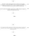
- FIG 1 is a flow chart of a state switching method according to an embodiment.
- the state switching method may be applied to a UE side, for example, performed by a UE on the UE side.
- the UE performing the method is configured with a data inactivity timer. If the data inactivity timer expires, the UE enters an RRC idle state.
- the state switching method may be applied to a scenario where an MBS traffic exists, for example, the UE is receiving data in a logical channel bearing MBS traffic data.
- a logical channel bearing MBS traffic data for multicast or broadcast in a cell may be defined as an MTCH, and an MTCH from which the UE can receive data merely in an RRC connected state may be defined as a connected-state MTCH.
- the state switching method including S101 and S102 may be performed by a chip with a state switching function in the UE, or by a baseband chip in the UE.
- the state switching method in the embodiment may include S101 and S102.
- a LTE starts or restarts a data inactivity timer in response to receiving data transmitted by a connected-state MTCH, wherein the connected-state MTCH is an MTCH that a terminal can receive merely in an RRC connected state.
- the UE switches from the RRC connected state to an RRC idle state in response to expiration of the data inactivity timer.
- the UE may be configured with one or more MAC entities, where each MAC entity is responsible for data processing of one or more logical channels.
- S101 may include: a MAC entity corresponding to the connected-state MTCH receiving a MAC SDU transmitted by the connected-state MTCH.
- the start or restart of the data inactivity timer may also be triggered.
- the other logical channels may include: a Dedicated Traffic Channel (DTCH), a Dedicated Control Channel (DCCH), and a Common Control Channel (CCCH). These logical channels may correspond to a same MAC entity or different MAC entities.
- DTCH Dedicated Traffic Channel
- DCCH Dedicated Control Channel
- CCCH Common Control Channel
- S 101 may include restarting or starting the data inactivity timer if any MAC entity of the UE receives a MAC SDU from the DTCH, the DCCH, the CCCH or the connected-state MTCH.
- S 102 may include releasing the RRC connection.
- a reason for the release may include a failure in RRC connection. Therefore, precise release of the RRC connection may be realized without affecting reception of the MBS traffic.
- the UE may perform state switching more reasonably, so as to avoid affecting reception of an MBS traffic.
- a data inactivity timer is set or reset in time by monitoring data transmission on a connected-state MTCH. Therefore, during transmission of the MBS traffic, the data inactivity timer can always be kept in a non-overtime state, so as to ensure that the UE does not switch to an RRC idle state when the MBS traffic is not completed.
- the UE may switch to the RRC idle state. Therefore, the reception of the MAC SDU in the connected-state MTCH by the UE may not be affected.
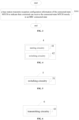
- FIG 2 is a flow chart of a state switching method according to an embodiment.
- the state switching method may be applied to a UE side, for example, performed by a UE on the UE side.
- the UE performing the method is configured with a data inactivity timer. If the data inactivity timer expires, the UE enters an RRC idle state.
- the state switching method may be applied to a scenario where an MBS traffic exists or may exist, for example, the UE is receiving or interested in receiving data in a logical channel bearing MBS traffic data.
- a logical channel bearing MBS traffic data for multicast or broadcast in a cell may be defined as an MTCH, and an MTCH from which the UE can receive data merely in an RRC connected state may be defined as a connected-state MTCH.
- the state switching method including S201 may be performed by a chip with a state switching function in the UE, or by a baseband chip in the UE.
- the state switching method in the embodiment may include S201.
- a UE switches from an RRC connected state to an RRC idle state in response to expiration of a data inactivity timer, and based on that there is no reception demand for data transmitted by a connected-state MTCH.
- the connected-state MTCH is an MTCH that a terminal can receive merely in an RRC connected state.
- S201 may include: determining whether there is the reception demand for data transmitted by the connected-state MTCH in response to expiration of the data inactivity timer; and switching from the RRC connected state to the RRC idle state based on that there is no reception demand for data transmitted by the connected-state MTCH.
- the method may further include S203.
- S203 the UE retains in the RRC connected state based on that there is the reception demand for data transmitted by the connected-state MTCH. Further, after receiving the data on the connected-state MTCH, the UE may switch from the RRC connected state to the RRC idle state.
- the reception demand for data transmitted by the connected-state MTCH includes: currently receiving the data transmitted by the connected-state MTCH.
- the reception demand for data transmitted by the connected-state MTCH includes: preparing to receive the data transmitted by the connected-state MTCH.
- the data transmitted by the connected-state MTCH is periodically transmitted, and said preparing to receive the data transmitted by the connected-state MTCH includes preparing to receive the data transmitted by the connected-state MTCH in a subsequent nearest transmission period although the data transmitted by the connected-state MTCH is not being currently received.
- the data inactivity timer may be restarted or started as any MAC entity of the LTE receives a MAC SDU from a DTCH, a DCCH or a CCCH. That is, in this embodiment, timing of LTE state switching is optimized from processing logic after the data inactivity timer is started or restarted.
- the data inactivity timer does not restart or start due to data transmission on the connected-state MTCH
- the UE first determines whether there is a demand to receive data transmitted by the connected-state MTCH, so as to ensure that the UE can accurately retains in the RRC connected state when there is or will be an MBS traffic.
- the UE adopting the solution of this embodiment can actively retain in the RRC connected state, so as to avoid delaying the reception of the MBS traffic caused by re-establishing the RRC connection in the future.
- S202 may include releasing the RRC connection.
- a reason for the release may include a failure in RRC connection. Therefore, precise release of the RRC connection may be realized without affecting reception of the MBS traffic.
- the RRC release operation is performed.
- the UE may perform state switching more reasonably, so as to avoid affecting reception of an MBS traffic. Specifically, when a timer expires and before performing state switching, it is determined whether there is a demand for receiving data transmitted by a connected-state MTCH. Therefore, by adding pre-judgment logic before performing the state switching, it is ensured that the UE can retain in an RRC connected state when the timer expires but there is a demand for receiving data transmitted by the connected-state MTCH.
- the UE in the RRC connected-state may switch to the RRC idle state. In this manner, it is ensured that the UE can still successfully receive the data of the connected-state MTCH when there is no data in other logical channels.
- the MTCH may be used to bear the MBS traffic.
- the connected-state MTCH may be used to bear the MBS traffic that requires the UE to receive data in the RRC connected state.
- the connected-state MTCH may at least include an MTCH configured with indication of supporting HARQ or configured with HARQ configuration information.
- the MTCH may be called a connected-state MTCH.
- the downlink data of the connected-state MTCH requires the UE to report other feedback information, which also makes the LTE to retain in the RRC connected state.
- the UE needs to report channel state information to the base station in the RRC connected state.
- the method further includes: receiving indication information which indicates whether a configured MTCH is the connected-state MTCH.
- the indication information may be specific or common signaling.
- the indication information may be included in reception configuration information which indicates information about the MTCH configured by a base station to the LTE.
- the indication information may include RRC state information which indicates an RRC state of the UE receiving the MTCH.
- the RRC state of the UE includes an RRC idle state (abbreviated as idle state), an RRC inactive state and an RRC connected state.
- the reception RRC state information of the connected-state MTCH merely includes the RRC connected state.
- the method may further include determining whether the configured MTCH is the connected-state MTCH based on reception configuration information of the configured MTCH. For example, if the reception configuration information of the configured MTCH merely includes the RRC connected state, the configured MTCH is regarded as the connected-state MTCH.
- the base station and the UE may not exchange additional indication information, and the reception configuration information does not add additional fields.
- the UE may determine whether the MTCH configured by the base station supports HARQ or whether there is HARQ configuration information according to the reception configuration information.
- the reception configuration information of the MTCH includes indication of whether HARQ is supported, or HARQ configuration information of the MTCH.
- the HARQ configuration information may include HARQ feedback parameters or configuration of feedback resources, so that it is determined whether the reception RRC state information of the MTCH merely includes the RRC connected state, which may save signaling overhead.
- the received MTCH configuration information indicates that the MTCH configured by the base station for the UE supports HARQ, it may be determined that the MTCH is a connected-state MTCH.
- the received MTCH configuration information includes the HARQ configuration information of the MTCH, it may be determined that the MTCH is a connected-state MTCH.
- reception configuration information may be a one-to-one correspondence between the reception configuration information and the MTCH.
- FIG 3 is a flow chart of a method for indicating a connected-state MTCH according to an embodiment.
- the method may be performed by a network side, such as by a base station on the network side.
- Cells maintained by the base station support an MBS traffic.
- MBS traffic there may be an MTCH that requires a LTE to retain in an RRC connected state for data reception. Therefore, the base station may notify the UE in advance whether an MTCH configured for the UE is a connected-state MTCH.
- the state switching method provided in following S301 may be performed by a chip with a state switching function in a network device, or may be performed by a baseband chip in the network device.
- the method in this embodiment may include S301.
- a base station transmits reception configuration information of the connected-state MTCH to indicate that a terminal can receive the connected-state MTCH merely in an RRC connected state.
- the method may further include: for each configured MTCH, determining whether the MTCH is a connected-state MTCH. If it is determined to be the connected-state MTCH, corresponding reception configuration information may be generated for the MTCH, and S301 is performed to transmit the reception configuration information to the UE.
- S301 may be performed for all MTCHs, such as traversing all MTCHs in configured cells to determine whether each MTCH is a connected-state MTCH.
- S301 may include: using HARQ configuration information configured in the reception configuration information to indicate that the terminal can receive the connected-state MTCH merely in the RRC connected state.
- S301 may include: using indication of supporting HARQ configured in the reception configuration information to indicate that the terminal can receive the connected-state MTCH merely in the RRC connected state.
- the reception configuration information when the reception configuration information is configured with indication of supporting HARQ or configured with HARQ configuration information, it may implicitly indicate that the MTCH is a connected-state MTCH. Accordingly, for the LTE that has received the reception configuration information, when it is found that the MTCH configured this time includes the indication of supporting HARQ or the HARQ configuration information, it may determine that the MTCH is a connected-state MTCH, and during reception of data transmitted by the MTCH, the UE needs to retain in the RRC connected state.
- S301 may include: using reception RRC state information which is included in the reception configuration information and merely includes the RRC connected state to indicate that the terminal can receive the connected-state MTCH merely in the RRC connected state, wherein the reception RRC state information is used to indicate an RRC state required to receive data transmitted by the connected-state MTCH.
- the base station uses a bitmap to indicate that the reception RRC state information of the connected-state MTCH merely includes the RRC connected state. That is, the base station may use the bitmap to indicate whether the reception RRC state information of the connected-state MTCH merely includes the RRC connected state.
- the base station may transmit reception configuration information of MTCH1, MTCH2, MTCH3, MTCH4, and MTCH5, and a 5-bit string may be used to indicate whether the RRC state information of the five MTCHs merely includes the RRC connected state.
- reception RRC state information corresponding to the MTCH merely includes the RRC connected state. Accordingly, if a string of the reception configuration information is 11101, it indicates that the reception RRC state information of MTCH1, MTCH2, MTCH3 and MTCH5 merely includes the RRC connected state, and the reception RRC state information of MTCH4 does not merely include the RRC connected state.
- S301 may include: transmitting the reception configuration information of the connected-state MTCH via system information or an MCCH.
- the base station may indicate the reception RRC state information of each MTCH in the system information or the MCCH, where the MCCH is a control channel indicating the reception configuration information such as a transmission cycle of the MTCH.
- the network indicates whether an MTCH configured for a UE is a connected-state MTCH via reception configuration information, so that the UE determines whether it is necessary to retain in an RRC connected state during data reception on a configured MTCH.
- the UE that has received the reception configuration information may perform the above state switching method to accurately control switching of its own state when the configured MTCH is a connected-state MTCH, so as to avoid affecting its own reception of an MBS traffic.
- the network side indicates the reception RRC state information of MTCH, so that the UE may receive data of the MTCH in a proper RRC state, thereby realizing an MBS traffic better.
- FIG 4 is a structural diagram of a state switching apparatus according to an embodiment. Those skilled in the art could understand that the state switching apparatus 4 may be applied to perform the method as shown in FIG 1 .
- the state switching apparatus 4 may include: a starting circuitry 41 configured to: start or restart a data inactivity timer in response to receiving data transmitted by a connected-state MTCH, wherein the connected-state MTCH is an MTCH that a terminal can receive merely in an RRC connected state; and a switching circuitry 42 configured to switch from the RRC connected state to an RRC idle state in response to expiration of the data inactivity timer.
- the state switching apparatus 4 may correspond to a chip with a state switching function in a UE, or to a chip with a data processing function, such as a System-On-Chip (SOC) or a baseband chip, or to a chip module including a chip with a state switching function in the UE, or to a chip module including a chip with a data processing function, or to the UE.
- a data processing function such as a System-On-Chip (SOC) or a baseband chip
- FIG 5 is a structural diagram of a state switching apparatus according to an embodiment. Those skilled in the art could understand that the state switching apparatus 5 may be applied to perform the method as shown in FIG 2 .
- the state switching apparatus 5 may include: a switching circuitry 51 configured to switch from an RRC connected state to an RRC idle state in response to expiration of a data inactivity timer, and based on that there is no reception demand for data transmitted by a connected-state MTCH, wherein the connected-state MTCH is an MTCH that a terminal can receive merely in the RRC connected state.
- the state switching apparatus 5 may correspond to a chip with a state switching function in a UE, or to a chip with a data processing function, such as an SOC or a baseband chip, or to a chip module including a chip with a state switching function in the UE, or to a chip module including a chip with a data processing function, or to the UE.
- FIG 6 is a structural diagram of an apparatus for indicating a connected-state MTCH according to an embodiment. Those skilled in the art could understand that the apparatus 6 for indicating the connected-state MTCH may be applied to perform the method as shown in FIG 3 .
- the apparatus 6 for indicating the connected-state MTCH may include: a transmitting circuitry 61 configured to transmit reception configuration information of the connected-state MTCH to indicate that a terminal can receive the connected-state MTCH merely in an RRC connected state.
- the apparatus 6 for indicating the connected-state MTCH may correspond to a chip with a state switching function in a network device, or to a chip with a data processing function, such as an SOC or a baseband chip, or to a chip module including a chip with a state switching function in the network device, or to a chip module including a chip with a data processing function, or to the network device.
- each module/unit of each apparatus and product described in the above embodiments may be a software module/unit or a hardware module/unit, or may be a software module/unit in part, and a hardware module/unit in part.
- each module/unit included therein may be implemented by hardware such as circuits; or, at least some modules/units may be implemented by a software program running on a processor integrated inside the chip, and the remaining (if any) part of the modules/units may be implemented by hardware such as circuits.
- each module/unit included therein may be implemented by hardware such as circuits. Different modules/units may be disposed in a same component (such as a chip or a circuit module) or in different components of the chip module.
- modules/units may be implemented by a software program running on a processor integrated inside the chip module, and the remaining (if any) part of the modules/units may be implemented by hardware such as circuits.
- each module/unit included therein may be implemented by hardware such as circuits.
- Different modules/units may be disposed in a same component (such as a chip or a circuit module) or in different components of the terminal.
- at least some modules/units may be implemented by a software program running on a processor integrated inside the terminal, and the remaining (if any) part of the modules/units may be implemented by hardware such as circuits.
- a storage medium having computer instructions stored therein is provided, wherein when the computer instructions are executed, any one of the above methods as shown in FIGS. 1 to 3 is performed.
- the storage medium may be a computer-readable storage medium, such as a non-volatile memory or a non-transitory memory.
- the storage medium may include a ROM, a RAM, a magnetic disk or an optical disk.
- a terminal including a memory and a processor
- the memory has computer instructions stored therein, and when the processor executes the computer instructions, the above methods as shown in FIGS. 1 and 2 is performed.
- the terminal may be a UE.
- a base station including a memory and a processor is provided, wherein the memory has computer instructions stored therein, and when the processor executes the computer instructions, the above method as shown in FIG 3 is performed.
- the base station may be an NR base station.
- the technical solutions of the present disclosure can be applied to 5G communication systems, 4G and 3G communication systems, and various new communication systems in the future, such as 6G and 7G communication systems.
- the technical solutions of the present disclosure also can be applied to different network architectures, including but not limited to a relay network architecture, a dual-link architecture, and a vehicle-to-everything architecture.
- a core network may be an Evolved Packet Core (EPC), 5G Core Network or a new core network in future communication systems.
- the 5G Core Network is composed of a set of devices, implements Access and Mobility Management Function (AMF) providing functions such as mobility management function, User Plane Function (UPF) providing functions such as packet routing and forwarding and Quality of Service (QoS) management, and Session Management Function (SMF) providing functions such as session management and IP address allocation and management.
- AMF Access and Mobility Management Function
- UPF User Plane Function
- QoS Quality of Service
- SMF Session Management Function
- EPC can be composed of MME that provides functions such as mobility management and gateway selection, Serving Gateway (S-GW) that provides functions such as data packet forwarding, and PDN Gateway (P-GW) that provides functions such as terminal address allocation and rate control.
- S-GW Serving Gateway
- PDN Gateway PDN Gateway
- the core network may include several new network elements to implement functions such as packet forwarding, MBS session management, QoS management, and transmission mode switching (switching between unicast and multicast/broadcast transmission modes). Another way is that the functionality may be implemented by network elements in an existing core network.
- the Base Station (BS) in the embodiments of the present disclosure may also be referred to as a base station equipment, and is an apparatus deployed in a Radio Access Network (RAN) to provide wireless communication functions.
- a Base Transceiver Station BTS
- An equipment that provides the base station function in a 3G network includes a Node B.
- An equipment that provides the base station function in a 4G network includes an evolved Node B (eNB).
- eNB evolved Node B
- an equipment that provides the base station function is an Access Point (AP).
- WLAN Wireless Local Area Network
- An equipment that provides the base station function in 5G New Radio (NR) includes a gNB and an ng-eNB, where the gNB and the terminal use NR technology to communicate, and the ng-eNB and the terminal use Evolved Universal Terrestrial Radio Access (E-UTRA) technology to communicate. Both the gNB and the ng-eNB can be connected to a 5G core network.
- the base station also refers to an equipment that provides the base station function in a new communication system in the future.
- the base station controller in the embodiments of the present disclosure is a device for managing base stations, such as a Base Station Controller (BSC) in a 2G network, a Radio Network Controller (RNC) in a 3G network, or a device that controls and manages a base station in a new communication system in the future.
- BSC Base Station Controller
- RNC Radio Network Controller
- the network side in the embodiments of the present disclosure refers to a communication network that provides communication services for terminals, including a base station of a radio access network, a BSC of a radio access network, and a device on the core network.
- a terminal in the embodiments of the present disclosure may refer to various forms of LTE, access terminal, user unit, user station, Mobile Station (MS), remote station, remote terminal, mobile equipment, user terminal, terminal equipment, wireless communication equipment, user agent or user device.
- the terminal equipment may further be a cellular phone, a cordless phone, a Session Initiation Protocol (SIP) phone, a Wireless Local Loop (WLL) station, a Personal Digital Assistant (PDA), a handheld device with a wireless communication function, a computing device or other processing devices connected to a wireless modems, an in-vehicle device, a wearable device, a terminal equipment in the future 5G network, or a terminal equipment in a future evolved Public Land Mobile Network (PLMN), which is not limited in the embodiments of the present disclosure.
- SIP Session Initiation Protocol
- WLL Wireless Local Loop
- PDA Personal Digital Assistant
- a unidirectional communication link from an access network to a terminal is defined as a downlink, data transmitted on the downlink is downlink data, and a transmission direction of the downlink data is called a downlink direction.
- a unidirectional communication link from a terminal to an access network is defined as an uplink, data transmitted on the uplink is uplink data, and a transmission direction of the uplink data is called an uplink direction.
- the “plurality” in the embodiments of the present disclosure refers to two or more.
- connection in the embodiments of the present disclosure refers to various connection ways such as direct connection or indirect connection to realize communication between devices, which is not limited in the embodiments of the present disclosure.
- the processor may be a Central Processing Unit (CPU), or other general processors, Digital Signal Processors (DSPs), Application Specific Integrated Circuits (ASICs), Field Programmable Gate Arrays (FPGAs) or other Programmable logic devices, discrete gates or transistor logic devices, discrete hardware components, and the like.
- a general processor may be a microprocessor or the processor may be any conventional processor or the like.
- the memory in the embodiments of the present disclosure may be either volatile memory or nonvolatile memory, or may include both volatile and nonvolatile memories.
- the non-volatile memory may be a Read-Only Memory (ROM), a Programmable ROM (PROM), an Erasable PROM (EPROM), an electrically Erasable EPROM (EEPROM), or a flash memory.
- the volatile memory may be a Random Access Memory (RAM) which functions as an external cache.
- RAM Static Random Access Memory
- DRAM Dynamic Random Access Memory
- SDRAM Synchronous Dynamic Random Access Memory
- DDR SDRAM Double Data Rate Synchronous Dynamic Random Access Memory
- ESDRAM Enhanced SDRAM
- SLDRAM Synchronous connection to DRAM
- DR-RAM Direct Rambus RAM
- the above embodiments may be implemented in whole or in part by software, hardware, firmware or any combination thereof.
- the above embodiments may be implemented in whole or in part in the form of a computer program product.
- the computer program product includes one or more computer instructions or computer programs.
- the procedures or functions according to the embodiments of the present disclosure are wholly or partially generated when the computer instructions or the computer programs are loaded or executed on a computer.
- the computer may be a general purpose computer, a special purpose computer, a computer network, or other programmable device.
- the computer instructions may be stored in a computer readable storage medium or transmitted from one computer readable storage medium to another computer readable storage medium, for example, the computer instructions may be transmitted from one website, computer, server or data center to another website, computer, server or data center by wire (e.g., infrared, wireless, microwave and etc.).
- the computer readable storage medium may be any available medium that can be accessed by a computer or a data storage device such as a server or a data center that contains one or more sets of available media.
- the available medium may be a magnetic medium (e.g., floppy disk, hard disk or magnetic tape), an optical medium (e.g., DVD), or a semiconductor medium.
- the semiconductor medium may be a solid disk.
- sequence numbers of the above-mentioned processes do not represent an execution sequence, and the execution sequence of each process should be determined by its function and inherent logic, which does not limit an implementation process of the embodiments of the present disclosure.
- the disclosed method, device and system may be implemented in other ways.
- the above device embodiments are merely illustrative, and for example, division of units is merely one logical division, and other divisions may be realized in practice, for example, a plurality of units or components may be combined or integrated into another system, or some features may be omitted, or not executed.
- the shown or discussed mutual coupling or direct coupling or communication connection may be an indirect coupling or communication connection via some interfaces, devices or units, and may be in an electrical, mechanical or other form.
- the units described as separate parts may or may not be physically separate, and parts shown as units may or may not be physical units, that is, may be disposed in one place, or may be distributed on a plurality of network units. Some or all of the units can be selected according to practical requirements to achieve the purpose of the solutions of the embodiments.
- functional units in the embodiments of the present disclosure may be integrated in one processing unit, or each unit may be physically separate, or two or more units may be integrated in one unit.
- the integrated units can be realized in a form of hardware, or in a form of hardware plus a software functional unit.
- the integrated units implemented in the form of the software functional unit may be stored in a computer readable storage medium.
- the software functional unit is stored in a storage medium and includes several instructions for causing a computer device (a personal computer, a server or a network device) to execute some steps of the methods in the embodiments of the present disclosure.
- the storage medium may be a medium for storing program codes, such as a U disk, a removable hard disk, a ROM, a RAM, a magnetic disk or an optical disk.
Landscapes
- Engineering & Computer Science (AREA)
- Computer Networks & Wireless Communication (AREA)
- Signal Processing (AREA)
- Mobile Radio Communication Systems (AREA)
Applications Claiming Priority (2)
| Application Number | Priority Date | Filing Date | Title |
|---|---|---|---|
| CN202010614412.XA CN113873687B (zh) | 2020-06-30 | 2020-06-30 | 状态转换方法及链接态mtch的指示方法、装置、存储介质、终端、基站 |
| PCT/CN2021/095697 WO2022001495A1 (zh) | 2020-06-30 | 2021-05-25 | 状态转换方法及链接态mtch的指示方法、装置、存储介质、终端、基站 |
Publications (2)
| Publication Number | Publication Date |
|---|---|
| EP4175404A1 true EP4175404A1 (de) | 2023-05-03 |
| EP4175404A4 EP4175404A4 (de) | 2024-03-13 |
Family
ID=78981429
Family Applications (1)
| Application Number | Title | Priority Date | Filing Date |
|---|---|---|---|
| EP21833356.5A Pending EP4175404A4 (de) | 2020-06-30 | 2021-05-25 | Zustandswechselverfahren, anzeigeverfahren und -vorrichtung für mtl-verbindungsstatus sowie speichermedium, endgerät und basisstation |
Country Status (6)
| Country | Link |
|---|---|
| US (1) | US20230254933A1 (de) |
| EP (1) | EP4175404A4 (de) |
| JP (1) | JP7545500B2 (de) |
| KR (1) | KR20230026462A (de) |
| CN (1) | CN113873687B (de) |
| WO (1) | WO2022001495A1 (de) |
Families Citing this family (7)
| Publication number | Priority date | Publication date | Assignee | Title |
|---|---|---|---|---|
| EP4124161B1 (de) * | 2021-01-15 | 2024-05-08 | ASUSTek Computer Inc. | Verfahren und vorrichtung zur kontrolle unbeabsichtigter bandbreitenumschaltung in einem drahtlosen kommunikationssystem |
| CN115022986A (zh) * | 2021-03-03 | 2022-09-06 | 上海朗帛通信技术有限公司 | 一种被用于无线通信的节点中的方法和装置 |
| EP4311371A4 (de) * | 2021-03-16 | 2025-07-09 | Kt Corp | Mbs-datensteuerungsverfahren und -vorrichtung |
| EP4412375A4 (de) * | 2021-10-01 | 2025-01-15 | LG Electronics Inc. | Verfahren und vorrichtung zur aktivierung und inaktivierung eines bandbreitenteils in einem drahtloskommunikationssystem |
| JP7502574B2 (ja) | 2021-10-13 | 2024-06-18 | 京セラ株式会社 | 通信方法、ユーザ装置、プロセッサ、プログラム、及び移動通信システム |
| CN116684827A (zh) * | 2022-02-23 | 2023-09-01 | 上海朗帛通信技术有限公司 | 一种被用于无线通信中的方法和装置 |
| WO2023245346A1 (en) * | 2022-06-20 | 2023-12-28 | Mediatek Singapore Pte. Ltd. | Methods and apparatus to set mrb configuration for ue to receive mbs multicast in rrc inactive state |
Family Cites Families (9)
| Publication number | Priority date | Publication date | Assignee | Title |
|---|---|---|---|---|
| CN102724770A (zh) * | 2012-05-09 | 2012-10-10 | 中国联合网络通信集团有限公司 | 用户设备状态转换方法、设备及系统 |
| US9307569B2 (en) * | 2012-06-08 | 2016-04-05 | Apple Inc. | Adjusting connection states of a mobile wireless device based on a period of inactivity |
| US9992759B2 (en) * | 2015-03-09 | 2018-06-05 | Ofinno Technologies, Llc | Downlink multicast channel and data channel in a wireless network |
| US10015776B2 (en) * | 2016-03-10 | 2018-07-03 | Qualcomm Incorporated | Low latency point to multipoint communication techniques |
| CN107277939B (zh) * | 2016-04-07 | 2020-02-14 | 北京信威通信技术股份有限公司 | 一种控制ue状态转换的方法 |
| CN109644322A (zh) * | 2016-08-25 | 2019-04-16 | 华为技术有限公司 | 传输数据的方法、终端设备和基站 |
| US11265132B2 (en) * | 2016-09-21 | 2022-03-01 | Kyocera Corporation | Enhancing utilization efficiency of radio resources in MBMS |
| US11452169B2 (en) * | 2018-08-15 | 2022-09-20 | Google Llc | Preventing inadvertent idle mode in multi-node connectivity environments |
| US12137495B2 (en) * | 2019-08-14 | 2024-11-05 | Beijing Xiaomi Mobile Software Co., Ltd. | Inactivity timer control method and device |
-
2020
- 2020-06-30 CN CN202010614412.XA patent/CN113873687B/zh active Active
-
2021
- 2021-05-25 EP EP21833356.5A patent/EP4175404A4/de active Pending
- 2021-05-25 KR KR1020237002117A patent/KR20230026462A/ko active Pending
- 2021-05-25 US US18/011,983 patent/US20230254933A1/en active Pending
- 2021-05-25 WO PCT/CN2021/095697 patent/WO2022001495A1/zh not_active Ceased
- 2021-05-25 JP JP2022580768A patent/JP7545500B2/ja active Active
Also Published As
| Publication number | Publication date |
|---|---|
| WO2022001495A1 (zh) | 2022-01-06 |
| KR20230026462A (ko) | 2023-02-24 |
| CN113873687B (zh) | 2025-03-14 |
| JP7545500B2 (ja) | 2024-09-04 |
| EP4175404A4 (de) | 2024-03-13 |
| US20230254933A1 (en) | 2023-08-10 |
| JP2023532697A (ja) | 2023-07-31 |
| CN113873687A (zh) | 2021-12-31 |
Similar Documents
| Publication | Publication Date | Title |
|---|---|---|
| US12501460B2 (en) | Data scheduling method, base station, and system | |
| US20230254933A1 (en) | State switching method and apparatus, method and apparatus for indicating connected-state mtch, storage medium, terminal and base station | |
| CN108541034B (zh) | 处理状态的转换的装置及方法 | |
| US12520380B2 (en) | Method and apparatus for multicast and broadcast services | |
| WO2020019187A1 (zh) | 一种信道监听方法及装置、终端设备、网络设备 | |
| CN119584099A (zh) | 用户设备、接入和移动管理功能设备及其进行的方法 | |
| US20190166559A1 (en) | Terminal state conversion method and apparatus | |
| CN111757358A (zh) | 用于寻呼的方法、接入网设备和终端设备 | |
| CN114501613A (zh) | 无线通信方法、网络设备和终端设备 | |
| JP2019536358A (ja) | データ送信/受信装置、方法及び通信システム | |
| EP3443787A1 (de) | Verfahren und vorrichtung zum funkruf an ein inaktives benutzergerät in einem drahtlosnetzwerk | |
| CN110100491B (zh) | 信息传输的方法、终端设备和网络设备 | |
| WO2023213140A1 (zh) | 通信方法、资源配置方法、设备、网络节点、系统及介质 | |
| JP2021510029A (ja) | ビーム障害回復の構成方法、装置及び通信システム | |
| WO2022127492A1 (zh) | 寻呼方法及装置、存储介质、终端、基站 | |
| CN115996485A (zh) | 非激活态多播业务发送、接收方法及装置 | |
| US20240023191A1 (en) | Method and apparatus for multicast and broadcast services | |
| WO2021232433A1 (zh) | 监听信道的方法、装置、设备及存储介质 | |
| US12543198B2 (en) | Method for receiving multicast service data, terminal device, and non-transitory computer-readable storage medium | |
| US20240365177A1 (en) | Method for determining configuration information, terminal device and chip | |
| EP4535921A1 (de) | Verfahren und vorrichtung zur bestimmung eines inaktiven multicast-dienstbereichs sowie verfahren und vorrichtung zur konfiguration eines inaktiven multicast-dienstbereichs | |
| EP4360401A1 (de) | Benachrichtigung über sgw-wechsel für eine oder mehrere pdn-verbindungen bei anwendung eines kombinierten sgw/pgw/smf-sets | |
| US20250240771A1 (en) | Paging with cell discontinuous transmission | |
| US20250240768A1 (en) | Paging with cell discontinuous transmission | |
| WO2025241192A1 (zh) | 信息传输方法、装置、设备、芯片、存储介质、产品及程序 |
Legal Events
| Date | Code | Title | Description |
|---|---|---|---|
| STAA | Information on the status of an ep patent application or granted ep patent |
Free format text: STATUS: THE INTERNATIONAL PUBLICATION HAS BEEN MADE |
|
| PUAI | Public reference made under article 153(3) epc to a published international application that has entered the european phase |
Free format text: ORIGINAL CODE: 0009012 |
|
| STAA | Information on the status of an ep patent application or granted ep patent |
Free format text: STATUS: REQUEST FOR EXAMINATION WAS MADE |
|
| 17P | Request for examination filed |
Effective date: 20221221 |
|
| AK | Designated contracting states |
Kind code of ref document: A1 Designated state(s): AL AT BE BG CH CY CZ DE DK EE ES FI FR GB GR HR HU IE IS IT LI LT LU LV MC MK MT NL NO PL PT RO RS SE SI SK SM TR |
|
| DAV | Request for validation of the european patent (deleted) | ||
| DAX | Request for extension of the european patent (deleted) | ||
| RIC1 | Information provided on ipc code assigned before grant |
Ipc: H04L 1/1812 20230101ALI20231120BHEP Ipc: H04W 76/40 20180101ALI20231120BHEP Ipc: H04W 76/38 20180101ALI20231120BHEP Ipc: H04W 76/27 20180101AFI20231120BHEP |
|
| A4 | Supplementary search report drawn up and despatched |
Effective date: 20240214 |
|
| RIC1 | Information provided on ipc code assigned before grant |
Ipc: H04L 1/1812 20230101ALI20240208BHEP Ipc: H04W 76/40 20180101ALI20240208BHEP Ipc: H04W 76/38 20180101ALI20240208BHEP Ipc: H04W 76/27 20180101AFI20240208BHEP |
|
| STAA | Information on the status of an ep patent application or granted ep patent |
Free format text: STATUS: EXAMINATION IS IN PROGRESS |
|
| 17Q | First examination report despatched |
Effective date: 20260409 |