EP4176701A1 - Dispositif de fixation d'au moins un outil agricole à un élément porteur - Google Patents
Dispositif de fixation d'au moins un outil agricole à un élément porteur Download PDFInfo
- Publication number
- EP4176701A1 EP4176701A1 EP21207109.6A EP21207109A EP4176701A1 EP 4176701 A1 EP4176701 A1 EP 4176701A1 EP 21207109 A EP21207109 A EP 21207109A EP 4176701 A1 EP4176701 A1 EP 4176701A1
- Authority
- EP
- European Patent Office
- Prior art keywords
- clamping
- carrier element
- base body
- lever
- joint
- Prior art date
- Legal status (The legal status is an assumption and is not a legal conclusion. Google has not performed a legal analysis and makes no representation as to the accuracy of the status listed.)
- Granted
Links
Images


Classifications
-
- A—HUMAN NECESSITIES
- A01—AGRICULTURE; FORESTRY; ANIMAL HUSBANDRY; HUNTING; TRAPPING; FISHING
- A01B—SOIL WORKING IN AGRICULTURE OR FORESTRY; PARTS, DETAILS, OR ACCESSORIES OF AGRICULTURAL MACHINES OR IMPLEMENTS, IN GENERAL
- A01B63/00—Lifting or adjusting devices or arrangements for agricultural machines or implements
- A01B63/14—Lifting or adjusting devices or arrangements for agricultural machines or implements for implements drawn by animals or tractors
- A01B63/24—Tools or tool-holders adjustable relatively to the frame
- A01B63/245—Tools or tool-holders adjustable relatively to the frame laterally adjustable
-
- A—HUMAN NECESSITIES
- A01—AGRICULTURE; FORESTRY; ANIMAL HUSBANDRY; HUNTING; TRAPPING; FISHING
- A01B—SOIL WORKING IN AGRICULTURE OR FORESTRY; PARTS, DETAILS, OR ACCESSORIES OF AGRICULTURAL MACHINES OR IMPLEMENTS, IN GENERAL
- A01B63/00—Lifting or adjusting devices or arrangements for agricultural machines or implements
- A01B63/14—Lifting or adjusting devices or arrangements for agricultural machines or implements for implements drawn by animals or tractors
- A01B63/24—Tools or tool-holders adjustable relatively to the frame
- A01B63/26—Tools or tool-holders adjustable relatively to the frame by man-power
Definitions
- the present invention relates to a device for fixing at least one agricultural working tool to a carrier element or for fixing a carrier element, to which an agricultural working tool is already fastened, to a supporting structure.
- a large number of support elements of the type in question each of which carries a device according to the invention together with a work tool, can be attached to a larger agricultural implement and pulled over the latter with the aid of a towing vehicle in order to work an agricultural soil.
- the working tools can be, for example, chopping tools, rakes, tines, tine stars, finger stars or the like.
- a device for fixing at least one agricultural working tool to a carrier element which has a base body with a guide receptacle that serves to receive the elongated carrier element and guide the base body along the carrier element.
- the guide receptacle can be, for example, a guide channel that passes through the base body and through which the elongate carrier element can extend.
- One or more agricultural working tools can be attached to the base body itself, which can be slid onto the carrier element. The working tools can then be moved together with the base body.
- the base body or the device according to the invention can form part of a supporting structure that can be towed by a towing vehicle.
- An elongate carrier element, to which at least one agricultural working tool is attached, can be displaced in the guide receptacle of the base body. The working tool can then be displaced relative to the base body together with the carrier element.
- the device according to the invention also includes a clamping lever which has a clamping hole.
- the clamping lever can be arranged relative to the base body in such a way that the clamping hole is aligned with the guide receptacle in the base body. Accordingly, the device can be slid onto the carrier element in such a way that the carrier element extends both through the clamping hole and through the guide receptacle in the base body.
- the clamping hole has a first non-round shape and a cross section of the guide receptacle in the base body has a second non-round shape. This means that torque can be transmitted from the clamping lever to the carrier element, which has a non-circular cross-section, and from the carrier element to the guide receptacle and thus to the base body.
- the device also includes an actuating device which is arranged on the base body.
- the clamping lever can be subjected to a clamping torque by means of the actuating device in such a way that it moves relative to the base body from a release position in which the device according to the invention and thus the work tool can be displaced along the carrier element or a carrier element with a work tool attached to it can be displaced in the base body into a clamping position in which the device according to the invention and thus the working tool is frictionally fixed to the carrier element due to the effect of the aforementioned torque transmission or the carrier element is frictionally fixed in the base body with the working tool attached to it.
- the angle of rotation of this rotational movement is between the existing game in the release position Clamping hole and guide receptacle on the one hand and carrier element on the other hand and is therefore relatively small.
- the advantage of the device according to the invention is that the agricultural working tools can be loosened and fixed on the elongated carrier element without the time-consuming turning of clamping screws.
- the actuating device for applying the clamping torque to the clamping lever can be designed in such a way that it advantageously requires only minor hand movements on the part of the operator and/or works with power assistance.
- the first non-round shape of the clamping hole of the clamping lever, the second non-round shape of the cross section of the guide receptacle in the base body and the third non-round shape of the cross section of the elongate carrier element enable a positive torque transmission between the clamping lever and the carrier element on the one hand and the carrier element and the guide receptacle of the base body on the other .
- This form-fit torque transferability enables the frictional clamping of the device according to the invention to the carrier element, which is desired according to the invention.
- the carrier element with the third non-round cross-sectional shape is held in a rotationally fixed manner in the guide receptacle of the base body.
- By applying the clamping torque to the clamping lever it attempts to rotate the carrier element held in the guide receptacle about its longitudinal axis. This is only possible within the scope of the existing play, since the carrier element is held in a rotationally fixed manner in the guide receptacle.
- the clamping lever thus twists the carrier element, which is held in a rotationally fixed manner in the guide receptacle of the base body.
- the first non-round shape of the clamping hole, the second non-round shape of the cross section of the guide receptacle and the third non-round shape of the cross section of the carrier element do not necessarily have to be identical. In terms of the present invention, it is entirely sufficient if their respective out-of-roundness allows a positive torque transmission between the clamping lever and the carrier element and between the carrier element and the guide receptacle of the base body.
- the first non-round shape, the second non-round shape and the third non-round shape are preferably configured identically.
- the size of the clamping hole, the size of the cross section of the guide mount and the size of the cross section of the carrier element it must be ensured that there is sufficient play between the surface of the carrier element on the one hand and the hole walls of the clamp hole and the guide walls of the guide mount on the other to be able to move the base body and the clamping lever along the carrier element when the clamping lever is in its release position, in which it is not subjected to a clamping torque.
- a polygonal shape is preferably selected for the first non-round shape and the second non-round shape.
- a square shape or a hexagonal shape are conceivable.
- Other polygonal shapes can also be used.
- the device according to the invention interacts with a carrier element whose cross section has the same polygonal shape as the clamping hole and the cross section of the guide receptacle in the base body.
- the clamping hole is advantageously designed to be completely closed to the environment.
- the carrier element is then surrounded on all sides by the clamping lever and held securely.
- the clamping hole it is conceivable for the clamping hole to be open on one side towards the surroundings, so that the carrier element can be gripped by the clamping lever in the manner of an open-end wrench.
- Such a construction would also ensure the positive transmission of torque from the clamping lever to the carrier element.
- the clamping lever can be configured as a double lever comprising two preferably identical partial levers.
- the two partial levers are then arranged on two opposite sides outside of the base body and can there encompass the carrier element at two spaced-apart points of the same.
- the clamping forces introduced into the carrier element by the clamping lever then act symmetrically with respect to the base body.
- the actuating device for applying the clamping torque to the clamping lever can have an actuating lever that can be actuated manually or with the assistance of a force, and a pulling element that is designed like a rod.
- the operating lever is connected in an articulated manner to the clamping lever via a pivot joint and the pull element is connected in an articulated manner to the operating lever via a first joint and to the base body in an articulated manner via a second joint.
- the first joint and the pivot joint are spaced from each other.
- the actuating lever is pivoted about the axis of the swivel joint from a release position, in which the clamping lever is in its release position, into a locking position, in which the clamping lever is in its clamping position.
- a distance between the first joint and the second joint initially increases against an elastic restoring force, then reaches a maximum value in a dead center position of the actuating lever and finally decreases again after passing through the dead center position due to the effect of the elastic restoring force.
- the first joint advantageously has a sleeve-like joint element through which the tension element passes.
- the joint element can be moved in the longitudinal direction of the tension element relative to the latter.
- the elastic restoring force can be brought about by at least one compression spring, which is supported on the tension element and presses the joint element in the direction of the second joint.
- the actuating device in the form of a power-assisted actuating means, for example in the form of at least one hydraulic cylinder or at least one pneumatic cylinder or at least one electric cylinder, which is arranged to act between the base body and the clamping lever and with the aid of which the clamping lever can be actuated with the clamping torque can be charged.
- a power-assisted actuating means for example in the form of at least one hydraulic cylinder or at least one pneumatic cylinder or at least one electric cylinder, which is arranged to act between the base body and the clamping lever and with the aid of which the clamping lever can be actuated with the clamping torque can be charged.
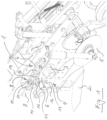
- the device 1 has a base body 4 which, in the exemplary embodiment shown, consists of two mirror-symmetrical side parts 16 and a sleeve part 17 connecting them.
- Two agricultural working tools 2 and 5, which are a cutting disc and a protractor, are attached to the base body 4 here.
- the interior of the sleeve part 17 that cannot be seen serves as a channel-like guide receptacle for receiving the elongate support element 3 and for guiding the base body 4 along the support element 3.
- the elongate support element 3 is designed as a square profile body.
- the carrier element 3 is mounted firmly on a supporting structure 18 that is of no further interest here.
- the base body 4 can be placed on the in 1
- the section of the carrier element 3 lying in front of the structure 18 can be freely displaced or completely removed from this section, provided that it is not frictionally clamped to the carrier element 3 .
- a clamping lever 6 designed as a double lever can be seen, which is shown in the side view according to FIG 2 and 3 looks pear shaped.
- One of the two partial levers of the clamping lever 6 is located in 1 in front of the front side part 16 and behind the rear side part 16 of the base body 4.
- the clamping lever 6 has one in the 2 and 3 characterized clamping hole 7, which has a square shape that corresponds to the square shape of the cross section of the support member 3.
- the cross section of the carrier element 3 is square
- the clamping hole 7 has a square shape
- the guide receptacle of the base body 4 formed by the interior of the sleeve part 17 also has a square cross section.
- the sleeve part 17 - and thus the entire base body 4 - and the clamping lever 6 can therefore not be rotated about the longitudinal axis of the carrier element 3, with the exception of the slight twistability permitted by the existing play.
- an actuating device 8 is identified, with the aid of which the clamping lever 6 can be moved from its in 2 shown release position in its in 3 shown clamping position and can be brought vice versa.
- the clamping lever 6 in the in 3 Visible clamping position, the clamping lever 6 is slightly further in the counterclockwise direction twisted than in the in 2 shown release position. This can be seen from the fact that the hole walls of the clamping hole 7 in 3 do not run parallel to the walls of the hollow profile of the carrier element 3.
- the clamping lever 6 In the clamping position that can be seen, the clamping lever 6 is acted upon by the actuating device 8 with a clamping torque which acts counterclockwise and tends to rotate the clamping lever 6 relative to the base body 4 or its side part 16 .
- the clamping lever 6 transmits this torque to the carrier element 3, which as a result also strives to rotate counterclockwise about its longitudinal axis. Since the carrier element 3 is held in a rotationally fixed manner in the guide receptacle formed by the interior of the sleeve part 17, such a rotation cannot take place or only within the scope of the play between the carrier element 3 and the walls of the guide receptacle.
- the base body 4 and the clamping lever 6 are frictionally clamped to the carrier element 3 .
- the base body 4 and the clamping lever 6 can no longer be displaced on the carrier element 3 in this clamped state.
- a frictional fixation of the base body 4 with its working tools 2 and 5 on the carrier element 3 is ensured.
- the actuating device 8 comprises an actuating lever 9 that can be actuated by hand and a tension element 10 designed as a tension rod.
- the actuating lever 9 is articulated via a pivot joint 11 with the in 2 connected to the left end of the clamping lever 6.
- the actuating lever 9 is connected in an articulated manner to the pulling element 10 via a first joint 12 .
- the tension element 10 is connected in an articulated manner to the base body 4 or its two side parts 16 via a second joint 13 .
- the rod-like pulling element 10 can thus be supported on the base body 4 .
- a sleeve-like joint element 14 can be seen, which is part of the construction of the first joint 12 between the operating lever 9 and the pulling element 10 .
- the sleeve-like joint element 14 is penetrated by the tension element 10 transversely to its sleeve axis, which corresponds to the joint axis of the first joint 12 .
- the joint element 14 can only rotate about the joint axis of the first joint 12 relative to the actuating lever 9 ; a linear movement of the joint element 14 relative to the actuating lever 9 is not possible.
- a compression spring 15 can be seen, which is supported at the upper end of the tension element 10 on this and then strives to move the joint element 14 into the 1 and 2 to press down.
- the procedure shown is as follows:
- the actuating lever 9 is released from its in 2 shown loose position by a little more than 90 ° clockwise about the pivot joint 11 pivoted.
- the distance between the first joint 12 and the second joint 13 increases because the first joint 12 moves away from the in 2 position shown in the in 3 shown position further up.
- the joint element 14 moves upwards to the same extent on the tension element 10, so that the compression spring 15 is increasingly compressed and its restoring force acting downward on the joint element 14 increases.
- the dead center position As soon as the maximum distance between the first joint 12 and the second joint 13 is reached, the restoring force of the compression spring 15 also reaches its maximum value.
- the position of the actuating lever 9 reached in this state is referred to as the dead center position. With continued pivoting movement of the actuating lever 9 in the clockwise direction, this dead center position is overcome and the 3 to be seen locking position of the operating lever 9 is reached.
- Support element 3 rests against the walls of the guide receptacle in sleeve part 17 . In this state, the frictional clamping of the base body 4 on the carrier element 3 is effected.
- an actuating device could be provided, for example in the form of a hydraulic cylinder, a pneumatic cylinder or an electric cylinder, the ends of which act, for example, between those points at which the second joint 13 and the pivot joint 11 are located in the exemplary embodiment shown.
- the device 1 can also be used to attach a carrier element 3, to which the working tools 2, 5 are already attached according to the invention or by other means, to which in 1 to be seen support structure 18 set.
- the device 1 can be integrated with its base body 4 into the support structure 18 .
- the carrier element 3 is then in 1 jammed further to the right in the guide mount of the base body 4.
Landscapes
- Life Sciences & Earth Sciences (AREA)
- Zoology (AREA)
- Engineering & Computer Science (AREA)
- Mechanical Engineering (AREA)
- Soil Sciences (AREA)
- Environmental Sciences (AREA)
- Clamps And Clips (AREA)
Priority Applications (1)
| Application Number | Priority Date | Filing Date | Title |
|---|---|---|---|
| EP21207109.6A EP4176701B1 (fr) | 2021-11-09 | 2021-11-09 | Dispositif de fixation d'au moins un outil agricole à un élément porteur |
Applications Claiming Priority (1)
| Application Number | Priority Date | Filing Date | Title |
|---|---|---|---|
| EP21207109.6A EP4176701B1 (fr) | 2021-11-09 | 2021-11-09 | Dispositif de fixation d'au moins un outil agricole à un élément porteur |
Publications (2)
| Publication Number | Publication Date |
|---|---|
| EP4176701A1 true EP4176701A1 (fr) | 2023-05-10 |
| EP4176701B1 EP4176701B1 (fr) | 2023-10-11 |
Family
ID=78592596
Family Applications (1)
| Application Number | Title | Priority Date | Filing Date |
|---|---|---|---|
| EP21207109.6A Active EP4176701B1 (fr) | 2021-11-09 | 2021-11-09 | Dispositif de fixation d'au moins un outil agricole à un élément porteur |
Country Status (1)
| Country | Link |
|---|---|
| EP (1) | EP4176701B1 (fr) |
Citations (5)
| Publication number | Priority date | Publication date | Assignee | Title |
|---|---|---|---|---|
| US20140230704A1 (en) * | 2013-02-19 | 2014-08-21 | Advanced Ag Concepts Inc. | Retractable inductor |
| US20150034343A1 (en) * | 2013-07-30 | 2015-02-05 | Great Plains Manufacturing, Incorporated | Agricultural implement tool support system |
| EP2842404A1 (fr) * | 2013-08-29 | 2015-03-04 | Rauch Landmaschinenfabrik Gmbh | Dispositif à recouvrir pour semoirs et/ou machines de travail du sol |
| US20160255759A1 (en) * | 2015-03-02 | 2016-09-08 | Deere & Company | Agricultural implement tool mounting assembly |
| US20190159396A1 (en) * | 2017-11-15 | 2019-05-30 | Benjamin L. Bauman | Tillage apparatus, systems, and methods |
-
2021
- 2021-11-09 EP EP21207109.6A patent/EP4176701B1/fr active Active
Patent Citations (5)
| Publication number | Priority date | Publication date | Assignee | Title |
|---|---|---|---|---|
| US20140230704A1 (en) * | 2013-02-19 | 2014-08-21 | Advanced Ag Concepts Inc. | Retractable inductor |
| US20150034343A1 (en) * | 2013-07-30 | 2015-02-05 | Great Plains Manufacturing, Incorporated | Agricultural implement tool support system |
| EP2842404A1 (fr) * | 2013-08-29 | 2015-03-04 | Rauch Landmaschinenfabrik Gmbh | Dispositif à recouvrir pour semoirs et/ou machines de travail du sol |
| US20160255759A1 (en) * | 2015-03-02 | 2016-09-08 | Deere & Company | Agricultural implement tool mounting assembly |
| US20190159396A1 (en) * | 2017-11-15 | 2019-05-30 | Benjamin L. Bauman | Tillage apparatus, systems, and methods |
Also Published As
| Publication number | Publication date |
|---|---|
| EP4176701B1 (fr) | 2023-10-11 |
Similar Documents
| Publication | Publication Date | Title |
|---|---|---|
| DE19963097C1 (de) | Zange zum Verpressen eines Werkstücks | |
| EP1671527B1 (fr) | Elément de liason | |
| DE2434900B2 (de) | Spannzange | |
| DE202016007588U1 (de) | Einschraubhilfe zum Halten und Ausrichten einer Schraube | |
| DE102016014860B3 (de) | Einschraubhilfe zum Halten und Ausrichten einer Schraube | |
| EP2913162A2 (fr) | Système de retour de conduite | |
| DE102015115433B4 (de) | Greif- und Hebevorrichtung zum Greifen von einem Greifgut mit zumindest zwei Greifzangen | |
| EP1995024B1 (fr) | Appareil de travail manuel | |
| DE1407644B1 (de) | Vorrichtung zur Regelung der Arbeitstiefe von an mit einem hydraulischen Kraftheber ausgeruesteten Schleppern angebauten landwirtschaftlichen Geraeten | |
| DE202009014386U1 (de) | Montagelehre | |
| DE69806760T2 (de) | Handwerkzeug mit unterstützungsarm und haltemechanismus und verfahren zum lösen der befestigungsmittel | |
| DE3420857A1 (de) | Greifvorrichtung mit greiferbacke | |
| EP4176701B1 (fr) | Dispositif de fixation d'au moins un outil agricole à un élément porteur | |
| DE19850268B4 (de) | Halteanordnung für Sauggreifer zur Handhabung von Gegenständen | |
| DE102004047337A1 (de) | Bohrständer | |
| DE102004018591B4 (de) | Bodenbearbeitungsgerät mit Winkelverstellung | |
| EP2881192A1 (fr) | Mâchoires pivotantes et appareil manuel motorisé | |
| DE102011115627B4 (de) | Spreizvorrichtung | |
| DE102022128192B3 (de) | Werkzeug zum Öffnen und Schließen von hydraulischen Schnellverschlusskupplungen | |
| DE19612752C2 (de) | Selbstklemmender Spannschlüssel | |
| EP0567720B1 (fr) | Liaison à axe débrochable | |
| DE9216760U1 (de) | Markiergerät zum Anbringen von Markierungen an Rohrmänteln | |
| DE69105258T2 (de) | Einspannvorrichtung zum innenseitigen greifen von hohlen körpern, insbesondere rohrförmigen körpern. | |
| EP4040937B1 (fr) | Dispositif de travail d'un sol agricole | |
| DE202020004924U1 (de) | Vorrichtung und Verwendung zum Lösen oder Festziehen von Langkörpern |
Legal Events
| Date | Code | Title | Description |
|---|---|---|---|
| PUAI | Public reference made under article 153(3) epc to a published international application that has entered the european phase |
Free format text: ORIGINAL CODE: 0009012 |
|
| STAA | Information on the status of an ep patent application or granted ep patent |
Free format text: STATUS: REQUEST FOR EXAMINATION WAS MADE |
|
| 17P | Request for examination filed |
Effective date: 20230322 |
|
| AK | Designated contracting states |
Kind code of ref document: A1 Designated state(s): AL AT BE BG CH CY CZ DE DK EE ES FI FR GB GR HR HU IE IS IT LI LT LU LV MC MK MT NL NO PL PT RO RS SE SI SK SM TR |
|
| GRAP | Despatch of communication of intention to grant a patent |
Free format text: ORIGINAL CODE: EPIDOSNIGR1 |
|
| STAA | Information on the status of an ep patent application or granted ep patent |
Free format text: STATUS: GRANT OF PATENT IS INTENDED |
|
| RIC1 | Information provided on ipc code assigned before grant |
Ipc: A01B 63/26 20060101ALI20230525BHEP Ipc: A01B 63/24 20060101AFI20230525BHEP |
|
| INTG | Intention to grant announced |
Effective date: 20230623 |
|
| P01 | Opt-out of the competence of the unified patent court (upc) registered |
Effective date: 20230717 |
|
| GRAS | Grant fee paid |
Free format text: ORIGINAL CODE: EPIDOSNIGR3 |
|
| GRAA | (expected) grant |
Free format text: ORIGINAL CODE: 0009210 |
|
| STAA | Information on the status of an ep patent application or granted ep patent |
Free format text: STATUS: THE PATENT HAS BEEN GRANTED |
|
| AK | Designated contracting states |
Kind code of ref document: B1 Designated state(s): AL AT BE BG CH CY CZ DE DK EE ES FI FR GB GR HR HU IE IS IT LI LT LU LV MC MK MT NL NO PL PT RO RS SE SI SK SM TR |
|
| REG | Reference to a national code |
Ref country code: GB Ref legal event code: FG4D Free format text: NOT ENGLISH |
|
| REG | Reference to a national code |
Ref country code: CH Ref legal event code: EP |
|
| REG | Reference to a national code |
Ref country code: DE Ref legal event code: R096 Ref document number: 502021001684 Country of ref document: DE |
|
| REG | Reference to a national code |
Ref country code: IE Ref legal event code: FG4D Free format text: LANGUAGE OF EP DOCUMENT: GERMAN |
|
| REG | Reference to a national code |
Ref country code: LT Ref legal event code: MG9D |
|
| REG | Reference to a national code |
Ref country code: NL Ref legal event code: MP Effective date: 20231011 |
|
| PG25 | Lapsed in a contracting state [announced via postgrant information from national office to epo] |
Ref country code: NL Free format text: LAPSE BECAUSE OF FAILURE TO SUBMIT A TRANSLATION OF THE DESCRIPTION OR TO PAY THE FEE WITHIN THE PRESCRIBED TIME-LIMIT Effective date: 20231011 |
|
| PG25 | Lapsed in a contracting state [announced via postgrant information from national office to epo] |
Ref country code: GR Free format text: LAPSE BECAUSE OF FAILURE TO SUBMIT A TRANSLATION OF THE DESCRIPTION OR TO PAY THE FEE WITHIN THE PRESCRIBED TIME-LIMIT Effective date: 20240112 |
|
| PG25 | Lapsed in a contracting state [announced via postgrant information from national office to epo] |
Ref country code: IS Free format text: LAPSE BECAUSE OF FAILURE TO SUBMIT A TRANSLATION OF THE DESCRIPTION OR TO PAY THE FEE WITHIN THE PRESCRIBED TIME-LIMIT Effective date: 20240211 |
|
| PG25 | Lapsed in a contracting state [announced via postgrant information from national office to epo] |
Ref country code: LT Free format text: LAPSE BECAUSE OF FAILURE TO SUBMIT A TRANSLATION OF THE DESCRIPTION OR TO PAY THE FEE WITHIN THE PRESCRIBED TIME-LIMIT Effective date: 20231011 |
|
| PG25 | Lapsed in a contracting state [announced via postgrant information from national office to epo] |
Ref country code: ES Free format text: LAPSE BECAUSE OF FAILURE TO SUBMIT A TRANSLATION OF THE DESCRIPTION OR TO PAY THE FEE WITHIN THE PRESCRIBED TIME-LIMIT Effective date: 20231011 |
|
| PG25 | Lapsed in a contracting state [announced via postgrant information from national office to epo] |
Ref country code: LT Free format text: LAPSE BECAUSE OF FAILURE TO SUBMIT A TRANSLATION OF THE DESCRIPTION OR TO PAY THE FEE WITHIN THE PRESCRIBED TIME-LIMIT Effective date: 20231011 Ref country code: IS Free format text: LAPSE BECAUSE OF FAILURE TO SUBMIT A TRANSLATION OF THE DESCRIPTION OR TO PAY THE FEE WITHIN THE PRESCRIBED TIME-LIMIT Effective date: 20240211 Ref country code: GR Free format text: LAPSE BECAUSE OF FAILURE TO SUBMIT A TRANSLATION OF THE DESCRIPTION OR TO PAY THE FEE WITHIN THE PRESCRIBED TIME-LIMIT Effective date: 20240112 Ref country code: ES Free format text: LAPSE BECAUSE OF FAILURE TO SUBMIT A TRANSLATION OF THE DESCRIPTION OR TO PAY THE FEE WITHIN THE PRESCRIBED TIME-LIMIT Effective date: 20231011 Ref country code: BG Free format text: LAPSE BECAUSE OF FAILURE TO SUBMIT A TRANSLATION OF THE DESCRIPTION OR TO PAY THE FEE WITHIN THE PRESCRIBED TIME-LIMIT Effective date: 20240111 Ref country code: PT Free format text: LAPSE BECAUSE OF FAILURE TO SUBMIT A TRANSLATION OF THE DESCRIPTION OR TO PAY THE FEE WITHIN THE PRESCRIBED TIME-LIMIT Effective date: 20240212 |
|
| PG25 | Lapsed in a contracting state [announced via postgrant information from national office to epo] |
Ref country code: SE Free format text: LAPSE BECAUSE OF FAILURE TO SUBMIT A TRANSLATION OF THE DESCRIPTION OR TO PAY THE FEE WITHIN THE PRESCRIBED TIME-LIMIT Effective date: 20231011 Ref country code: RS Free format text: LAPSE BECAUSE OF FAILURE TO SUBMIT A TRANSLATION OF THE DESCRIPTION OR TO PAY THE FEE WITHIN THE PRESCRIBED TIME-LIMIT Effective date: 20231011 Ref country code: PL Free format text: LAPSE BECAUSE OF FAILURE TO SUBMIT A TRANSLATION OF THE DESCRIPTION OR TO PAY THE FEE WITHIN THE PRESCRIBED TIME-LIMIT Effective date: 20231011 Ref country code: NO Free format text: LAPSE BECAUSE OF FAILURE TO SUBMIT A TRANSLATION OF THE DESCRIPTION OR TO PAY THE FEE WITHIN THE PRESCRIBED TIME-LIMIT Effective date: 20240111 Ref country code: LV Free format text: LAPSE BECAUSE OF FAILURE TO SUBMIT A TRANSLATION OF THE DESCRIPTION OR TO PAY THE FEE WITHIN THE PRESCRIBED TIME-LIMIT Effective date: 20231011 Ref country code: HR Free format text: LAPSE BECAUSE OF FAILURE TO SUBMIT A TRANSLATION OF THE DESCRIPTION OR TO PAY THE FEE WITHIN THE PRESCRIBED TIME-LIMIT Effective date: 20231011 |
|
| PG25 | Lapsed in a contracting state [announced via postgrant information from national office to epo] |
Ref country code: DK Free format text: LAPSE BECAUSE OF FAILURE TO SUBMIT A TRANSLATION OF THE DESCRIPTION OR TO PAY THE FEE WITHIN THE PRESCRIBED TIME-LIMIT Effective date: 20231011 |
|
| REG | Reference to a national code |
Ref country code: DE Ref legal event code: R097 Ref document number: 502021001684 Country of ref document: DE |
|
| PG25 | Lapsed in a contracting state [announced via postgrant information from national office to epo] |
Ref country code: LU Free format text: LAPSE BECAUSE OF NON-PAYMENT OF DUE FEES Effective date: 20231109 |
|
| PG25 | Lapsed in a contracting state [announced via postgrant information from national office to epo] |
Ref country code: CZ Free format text: LAPSE BECAUSE OF FAILURE TO SUBMIT A TRANSLATION OF THE DESCRIPTION OR TO PAY THE FEE WITHIN THE PRESCRIBED TIME-LIMIT Effective date: 20231011 |
|
| PG25 | Lapsed in a contracting state [announced via postgrant information from national office to epo] |
Ref country code: SK Free format text: LAPSE BECAUSE OF FAILURE TO SUBMIT A TRANSLATION OF THE DESCRIPTION OR TO PAY THE FEE WITHIN THE PRESCRIBED TIME-LIMIT Effective date: 20231011 |
|
| PG25 | Lapsed in a contracting state [announced via postgrant information from national office to epo] |
Ref country code: SM Free format text: LAPSE BECAUSE OF FAILURE TO SUBMIT A TRANSLATION OF THE DESCRIPTION OR TO PAY THE FEE WITHIN THE PRESCRIBED TIME-LIMIT Effective date: 20231011 Ref country code: SK Free format text: LAPSE BECAUSE OF FAILURE TO SUBMIT A TRANSLATION OF THE DESCRIPTION OR TO PAY THE FEE WITHIN THE PRESCRIBED TIME-LIMIT Effective date: 20231011 Ref country code: RO Free format text: LAPSE BECAUSE OF FAILURE TO SUBMIT A TRANSLATION OF THE DESCRIPTION OR TO PAY THE FEE WITHIN THE PRESCRIBED TIME-LIMIT Effective date: 20231011 Ref country code: LU Free format text: LAPSE BECAUSE OF NON-PAYMENT OF DUE FEES Effective date: 20231109 Ref country code: IT Free format text: LAPSE BECAUSE OF FAILURE TO SUBMIT A TRANSLATION OF THE DESCRIPTION OR TO PAY THE FEE WITHIN THE PRESCRIBED TIME-LIMIT Effective date: 20231011 Ref country code: EE Free format text: LAPSE BECAUSE OF FAILURE TO SUBMIT A TRANSLATION OF THE DESCRIPTION OR TO PAY THE FEE WITHIN THE PRESCRIBED TIME-LIMIT Effective date: 20231011 Ref country code: DK Free format text: LAPSE BECAUSE OF FAILURE TO SUBMIT A TRANSLATION OF THE DESCRIPTION OR TO PAY THE FEE WITHIN THE PRESCRIBED TIME-LIMIT Effective date: 20231011 Ref country code: CZ Free format text: LAPSE BECAUSE OF FAILURE TO SUBMIT A TRANSLATION OF THE DESCRIPTION OR TO PAY THE FEE WITHIN THE PRESCRIBED TIME-LIMIT Effective date: 20231011 |
|
| REG | Reference to a national code |
Ref country code: BE Ref legal event code: MM Effective date: 20231130 |
|
| PLBE | No opposition filed within time limit |
Free format text: ORIGINAL CODE: 0009261 |
|
| STAA | Information on the status of an ep patent application or granted ep patent |
Free format text: STATUS: NO OPPOSITION FILED WITHIN TIME LIMIT |
|
| PG25 | Lapsed in a contracting state [announced via postgrant information from national office to epo] |
Ref country code: MC Free format text: LAPSE BECAUSE OF FAILURE TO SUBMIT A TRANSLATION OF THE DESCRIPTION OR TO PAY THE FEE WITHIN THE PRESCRIBED TIME-LIMIT Effective date: 20231011 |
|
| PG25 | Lapsed in a contracting state [announced via postgrant information from national office to epo] |
Ref country code: MC Free format text: LAPSE BECAUSE OF FAILURE TO SUBMIT A TRANSLATION OF THE DESCRIPTION OR TO PAY THE FEE WITHIN THE PRESCRIBED TIME-LIMIT Effective date: 20231011 |
|
| REG | Reference to a national code |
Ref country code: IE Ref legal event code: MM4A |
|
| 26N | No opposition filed |
Effective date: 20240712 |
|
| PG25 | Lapsed in a contracting state [announced via postgrant information from national office to epo] |
Ref country code: IE Free format text: LAPSE BECAUSE OF NON-PAYMENT OF DUE FEES Effective date: 20231109 |
|
| PG25 | Lapsed in a contracting state [announced via postgrant information from national office to epo] |
Ref country code: BE Free format text: LAPSE BECAUSE OF NON-PAYMENT OF DUE FEES Effective date: 20231130 |
|
| PG25 | Lapsed in a contracting state [announced via postgrant information from national office to epo] |
Ref country code: SI Free format text: LAPSE BECAUSE OF FAILURE TO SUBMIT A TRANSLATION OF THE DESCRIPTION OR TO PAY THE FEE WITHIN THE PRESCRIBED TIME-LIMIT Effective date: 20231011 |
|
| PG25 | Lapsed in a contracting state [announced via postgrant information from national office to epo] |
Ref country code: SI Free format text: LAPSE BECAUSE OF FAILURE TO SUBMIT A TRANSLATION OF THE DESCRIPTION OR TO PAY THE FEE WITHIN THE PRESCRIBED TIME-LIMIT Effective date: 20231011 Ref country code: IE Free format text: LAPSE BECAUSE OF NON-PAYMENT OF DUE FEES Effective date: 20231109 Ref country code: BE Free format text: LAPSE BECAUSE OF NON-PAYMENT OF DUE FEES Effective date: 20231130 |
|
| PG25 | Lapsed in a contracting state [announced via postgrant information from national office to epo] |
Ref country code: FI Free format text: LAPSE BECAUSE OF FAILURE TO SUBMIT A TRANSLATION OF THE DESCRIPTION OR TO PAY THE FEE WITHIN THE PRESCRIBED TIME-LIMIT Effective date: 20231011 |
|
| PG25 | Lapsed in a contracting state [announced via postgrant information from national office to epo] |
Ref country code: CY Free format text: LAPSE BECAUSE OF FAILURE TO SUBMIT A TRANSLATION OF THE DESCRIPTION OR TO PAY THE FEE WITHIN THE PRESCRIBED TIME-LIMIT; INVALID AB INITIO Effective date: 20211109 |
|
| REG | Reference to a national code |
Ref country code: CH Ref legal event code: U11 Free format text: ST27 STATUS EVENT CODE: U-0-0-U10-U11 (AS PROVIDED BY THE NATIONAL OFFICE) Effective date: 20251201 |
|
| PG25 | Lapsed in a contracting state [announced via postgrant information from national office to epo] |
Ref country code: TR Free format text: LAPSE BECAUSE OF FAILURE TO SUBMIT A TRANSLATION OF THE DESCRIPTION OR TO PAY THE FEE WITHIN THE PRESCRIBED TIME-LIMIT Effective date: 20231011 |
|
| PGFP | Annual fee paid to national office [announced via postgrant information from national office to epo] |
Ref country code: DE Payment date: 20251029 Year of fee payment: 5 |
|
| PGFP | Annual fee paid to national office [announced via postgrant information from national office to epo] |
Ref country code: AT Payment date: 20260113 Year of fee payment: 5 |
|
| PGFP | Annual fee paid to national office [announced via postgrant information from national office to epo] |
Ref country code: FR Payment date: 20251126 Year of fee payment: 5 |
|
| PGFP | Annual fee paid to national office [announced via postgrant information from national office to epo] |
Ref country code: CH Payment date: 20251201 Year of fee payment: 5 |
|
| PG25 | Lapsed in a contracting state [announced via postgrant information from national office to epo] |
Ref country code: HU Free format text: LAPSE BECAUSE OF FAILURE TO SUBMIT A TRANSLATION OF THE DESCRIPTION OR TO PAY THE FEE WITHIN THE PRESCRIBED TIME-LIMIT; INVALID AB INITIO Effective date: 20211109 |