EP4177155A1 - Système de propulsion marine - Google Patents
Système de propulsion marine Download PDFInfo
- Publication number
- EP4177155A1 EP4177155A1 EP22205548.5A EP22205548A EP4177155A1 EP 4177155 A1 EP4177155 A1 EP 4177155A1 EP 22205548 A EP22205548 A EP 22205548A EP 4177155 A1 EP4177155 A1 EP 4177155A1
- Authority
- EP
- European Patent Office
- Prior art keywords
- hull
- propulsion device
- auxiliary
- main
- orientation
- Prior art date
- Legal status (The legal status is an assumption and is not a legal conclusion. Google has not performed a legal analysis and makes no representation as to the accuracy of the status listed.)
- Pending
Links
Images




Classifications
-
- B—PERFORMING OPERATIONS; TRANSPORTING
- B63—SHIPS OR OTHER WATERBORNE VESSELS; RELATED EQUIPMENT
- B63H—MARINE PROPULSION OR STEERING
- B63H25/00—Steering; Slowing-down otherwise than by use of propulsive elements; Dynamic anchoring, i.e. positioning vessels by means of main or auxiliary propulsive elements
- B63H25/42—Steering or dynamic anchoring by propulsive elements; Steering or dynamic anchoring by propellers used therefor only; Steering or dynamic anchoring by rudders carrying propellers
-
- B—PERFORMING OPERATIONS; TRANSPORTING
- B63—SHIPS OR OTHER WATERBORNE VESSELS; RELATED EQUIPMENT
- B63H—MARINE PROPULSION OR STEERING
- B63H20/00—Outboard propulsion units, e.g. outboard motors or Z-drives; Arrangements thereof on vessels
- B63H20/08—Means enabling movement of the position of the propulsion element, e.g. for trim, tilt or steering; Control of trim or tilt
- B63H20/12—Means enabling steering
-
- B—PERFORMING OPERATIONS; TRANSPORTING
- B63—SHIPS OR OTHER WATERBORNE VESSELS; RELATED EQUIPMENT
- B63H—MARINE PROPULSION OR STEERING
- B63H21/00—Use of propulsion power plant or units on vessels
- B63H21/21—Control means for engine or transmission, specially adapted for use on marine vessels
-
- B—PERFORMING OPERATIONS; TRANSPORTING
- B63—SHIPS OR OTHER WATERBORNE VESSELS; RELATED EQUIPMENT
- B63H—MARINE PROPULSION OR STEERING
- B63H20/00—Outboard propulsion units, e.g. outboard motors or Z-drives; Arrangements thereof on vessels
- B63H2020/003—Arrangements of two, or more outboard propulsion units
-
- B—PERFORMING OPERATIONS; TRANSPORTING
- B63—SHIPS OR OTHER WATERBORNE VESSELS; RELATED EQUIPMENT
- B63H—MARINE PROPULSION OR STEERING
- B63H21/00—Use of propulsion power plant or units on vessels
- B63H21/21—Control means for engine or transmission, specially adapted for use on marine vessels
- B63H2021/216—Control means for engine or transmission, specially adapted for use on marine vessels using electric control means
-
- B—PERFORMING OPERATIONS; TRANSPORTING
- B63—SHIPS OR OTHER WATERBORNE VESSELS; RELATED EQUIPMENT
- B63H—MARINE PROPULSION OR STEERING
- B63H25/00—Steering; Slowing-down otherwise than by use of propulsive elements; Dynamic anchoring, i.e. positioning vessels by means of main or auxiliary propulsive elements
- B63H25/02—Initiating means for steering, for slowing down, otherwise than by use of propulsive elements, or for dynamic anchoring
- B63H2025/026—Initiating means for steering, for slowing down, otherwise than by use of propulsive elements, or for dynamic anchoring using multi-axis control levers, or the like, e.g. joysticks, wherein at least one degree of freedom is employed for steering, slowing down, or dynamic anchoring
-
- B—PERFORMING OPERATIONS; TRANSPORTING
- B63—SHIPS OR OTHER WATERBORNE VESSELS; RELATED EQUIPMENT
- B63H—MARINE PROPULSION OR STEERING
- B63H25/00—Steering; Slowing-down otherwise than by use of propulsive elements; Dynamic anchoring, i.e. positioning vessels by means of main or auxiliary propulsive elements
- B63H25/02—Initiating means for steering, for slowing down, otherwise than by use of propulsive elements, or for dynamic anchoring
Definitions
- the present invention relates to a marine propulsion system.
- a marine propulsion system including a main propulsion device and an auxiliary propulsion device, both of which are attached to the stern of a hull, is known in general.
- Such a marine propulsion system is disclosed in JP 2000-344193 A , for example.
- JP 2000-344193 A discloses an automatic return navigation device including a main propulsion device attached to the stern of a hull, an auxiliary propulsion device attached to the stern of the hull, and a controller that performs a control to maintain the hull at a target point specified by a user.
- the controller drives only the auxiliary propulsion device to move (return) the hull to the target point.
- the controller stops the auxiliary propulsion device again when the hull returns to the target point. In the control to return the hull to the target point, only the auxiliary propulsion device is driven instead of driving both the main propulsion device and the auxiliary propulsion device.
- JP 2000-344193 A Conventionally, there has been known a fixed point holding control, STAYPOINT (registered trademark) control, to maintain the orientation of a bow at a target orientation specified by a user and maintain the position of a hull at a target point specified by the user.
- STAYPOINT registered trademark
- a control is conceivably performed to drive only the auxiliary propulsion device instead of driving both the main propulsion device and the auxiliary propulsion device.
- a marine propulsion system includes a main propulsion device attached to a stern of a hull and configured to rotate in a right-left direction to change a direction of a thrust, an auxiliary propulsion device attached to the stern, including an electric motor configured to drive an auxiliary thruster to generate a thrust, configured to rotate in the right-left direction to change a direction of the thrust, and having a maximum output smaller than a maximum output of the main propulsion device, and a controller configured or programmed to perform a fixed point holding control to maintain an orientation of a bow of the hull at a target orientation and maintain a position of the hull at a target point by causing the main propulsion device and the auxiliary propulsion device to cooperate with each other.
- a marine propulsion system includes the controller configured or programmed to perform the fixed point holding control, STAYPOINT (registered trademark) control, to maintain the orientation of the bow of the hull at the target orientation and maintain the position of the hull at the target point by causing the main propulsion device and the auxiliary propulsion device to cooperate with each other. Accordingly, unlike a case in which only the auxiliary propulsion device is driven in the fixed point holding control, the main propulsion device and the auxiliary propulsion device are caused to cooperate with each other to flexibly rotate and move the hull so as to maintain the orientation of the bow of the hull at the target orientation and maintain the position of the hull at the target point.
- STAYPOINT registered trademark
- the auxiliary propulsion device includes the electric motor to drive the auxiliary thruster to generate a thrust. Accordingly, as compared with a case in which the main propulsion device is driven and the auxiliary propulsion device is an engine propulsion device, the amount of carbon dioxide emitted from the auxiliary propulsion device is reduced. Thus, the hull including the main propulsion device and the auxiliary propulsion device is held at a fixed point while environmental burdens associated with driving of the auxiliary propulsion device are reduced as much as possible.
- the main propulsion device is preferably provided on a centerline of the hull in the right-left direction
- the auxiliary propulsion device is preferably provided to one side of the centerline of the hull in the right-left direction. Accordingly, in a marine vessel including the main propulsion device provided on the centerline of the hull in the right-left direction, and the auxiliary propulsion device provided to one side of the centerline of the hull in the right-left direction, the main propulsion device and the auxiliary propulsion device are caused to cooperate with each other to flexibly rotate and move the hull, and thus the directions and magnitudes of the thrusts of the main propulsion device and the auxiliary propulsion device are adjusted in the fixed point holding control.
- the auxiliary propulsion device preferably has a right-left rotatable angle range to change the direction of the thrust larger than a right-left rotatable angle range of the main propulsion device
- the controller is preferably configured or programmed to rotate the hull by driving the auxiliary propulsion device in the fixed point holding control. Accordingly, the hull is rotated (pivot-turned) by the electric motor-driven (electric) auxiliary propulsion device that has the right-left rotatable angle range to change the direction of the thrust larger than the right-left rotatable angle range of the main propulsion device such that a change in the position of the hull becomes smaller.
- the main propulsion device preferably includes an engine configured to drive a main thruster to generate a thrust and having a maximum value and a minimum value of a power range larger than a maximum value and a minimum value of a power range of the electric motor
- the controller is preferably configured or programmed to limit the power range of the engine by matching an upper limit value of the power range of the engine with the maximum value of the power range of the electric motor while the main propulsion device and the auxiliary propulsion device are caused to cooperate with each other to move the hull, and to limit the power range of the electric motor by matching a lower limit value of the power range of the electric motor with the minimum value of the power range of the engine while the main propulsion device and the auxiliary propulsion device are caused to cooperate with each other to move the hull.
- the power range of the engine and the power range of the electric motor are adjusted to be equivalent to each other, and thus when the main propulsion device and the auxiliary propulsion device are caused to cooperate with each other, the output of the engine and the output of the electric motor are prevented from being out of balance.
- the controller is preferably configured or programmed to rotate the hull by driving the auxiliary thruster to generate the thrust from the auxiliary propulsion device while a main thruster configured to generate a thrust from the main propulsion device is stopped when the hull is rotated to maintain the orientation of the bow at the target orientation in the fixed point holding control. Accordingly, the hull is rotated only by the electric auxiliary propulsion device, and thus the hull is quietly rotated. Furthermore, a thrust is generated only from the electric motor-driven (electric) auxiliary propulsion device during rotation of the hull, and thus environmental burdens during rotation of the hull are reduced.
- the controller is preferably configured or programmed to rotate the hull about a center of gravity of the hull on the spot while holding the position of the hull. Accordingly, the hull is rotated on the spot without changing the position of the hull, and thus the accuracy of maintaining the target point in the fixed point holding control is improved.
- the controller is preferably configured or programmed to, when the hull is moved to maintain the position of the hull at the target point in the fixed point holding control, move the hull laterally or diagonally while maintaining the orientation of the bow by simultaneously driving a main thruster configured to generate the thrust from the main propulsion device and the auxiliary thruster configured to generate the thrust from the auxiliary propulsion device, and move the hull in a forward-rearward direction by driving the main thruster while the auxiliary thruster is stopped.
- the main thruster and the auxiliary thruster are simultaneously driven (caused to cooperate with each other) such that the hull is moved laterally or diagonally while the orientation of the bow is maintained, and the hull is moved in the forward-rearward direction by driving only the main thruster.
- the controller is preferably configured or programmed to move the hull laterally or diagonally while maintaining the orientation of the bow by positioning an intersection of an output vector of the main thruster and an output vector of the auxiliary thruster on a straight line passing through a center of gravity of the hull and the target point and setting, in a direction from the center of gravity to the target point, a direction of a resultant force of the output vector of the main thruster and the output vector of the auxiliary thruster that indicates a moving direction of the hull.
- the main propulsion device and the auxiliary propulsion device are not provided in a well-balanced manner with respect to the centerline of the hull in the right-left direction, the hull is moved laterally or diagonally while the orientation of the bow is maintained.
- the controller is preferably configured or programmed to cause a direction of an output vector of the main thruster and a direction of an output vector of the auxiliary thruster to be opposite to each other in the forward-rearward direction when the hull is moved laterally or diagonally while the orientation of the bow is maintained. Accordingly, the direction of the output vector of the main thruster and the direction of the output vector of the auxiliary thruster are opposite to each other, and thus the hull is easily moved laterally or diagonally while the orientation of the bow is maintained.
- the controller is preferably configured or programmed to perform a control to rotate the hull to maintain the orientation of the bow at the target orientation and a control to move the hull to maintain the position of the hull at the target point at different timings in the fixed point holding control. Accordingly, rotating the hull to maintain the orientation of the bow at the target orientation and moving the hull to maintain the position of the hull at the target point are separated from each other such that a change in the position of the hull during rotation of the hull is significantly reduced or prevented, and a change in the orientation of the bow during movement of the hull is significantly reduced or prevented.
- the main propulsion device is preferably an engine outboard motor including an engine configured to drive a main propeller to generate a thrust and provided on a centerline of the hull in the right-left direction
- the auxiliary propulsion device is preferably an electric outboard motor including the electric motor configured to drive an auxiliary propeller corresponding to the auxiliary thruster and provided to one side of the centerline of the hull in the right-left direction. Accordingly, environmental burdens are reduced due to driving of the electric outboard motor, and the hull including the engine outboard motor and the electric outboard motor is held at a fixed point.
- FIGS. 1 to 11 The structure of a marine vessel 100 including a marine propulsion system 102 according to preferred embodiments is now described with reference to FIGS. 1 to 11 .
- arrow FWD represents the forward movement direction of the marine vessel 100 in a forward-rearward direction
- arrow BWD represents the rearward movement direction of the marine vessel 100 in the forward-rearward direction
- Arrow R represents the starboard direction of the marine vessel 100 in a right-left direction (a direction perpendicular to the forward-rearward direction)
- arrow L represents the portside direction of the marine vessel 100 in the right-left direction.
- the marine vessel 100 includes a hull 101 and the marine propulsion system 102 provided on or in the hull 101.
- the hull 101 may be a hull of a fishing boat or a fishing vessel for a user to fish, or a relatively large hull such as a passenger vessel, for example.
- the marine propulsion system 102 includes a main propulsion device 1, an auxiliary propulsion device 2, a joystick 3, a display 4 that displays navigation-related information, etc., an orientation sensor 5a, a position sensor 5b, and a controller 6.
- the joystick 3, the display 4, the orientation sensor 5a, the position sensor 5b, and the controller 6 are mounted on or in the hull 101.
- the marine propulsion system 102 (controller 6) performs a fixed point holding control, STAYPOINT (registered trademark) control, to maintain the orientation T1 (FWD) of a bow 101a of the hull 101 at a target orientation T2 (see FIG. 7 ) and maintain the position A1 of the hull 101 at a target point A2 (see FIG. 7 ) by causing the main propulsion device 1 and the auxiliary propulsion device 2 to cooperate with each other.
- the fixed point holding control without the user maneuvering the marine vessel, the orientation of the hull 101 is automatically maintained at the target orientation T2 specified by the user, and the position of the hull 101 is automatically maintained at the target point A2 specified by the user.
- the fixed point holding control is described below in detail.
- the "cooperate” described above refers to automatically driving the main propulsion device 1 and the auxiliary propulsion device 2 at the same time to adjust mutual rudder angles (orientations) and mutual outputs of the main propulsion device 1 and the auxiliary propulsion device 2 in the fixed point holding control, STAYPOINT (registered trademark) control.
- the main propulsion device 1 is an engine outboard motor including an engine 12 to drive a main propeller 10 to generate a thrust.
- the main propulsion device 1 is provided on a centerline ⁇ of the hull 101 in the right-left direction.
- the main propulsion device 1 rotates in the right-left direction to change the direction of the thrust of the main propeller 10.
- the main propeller 10 is an example of a "main thruster”.
- the main propulsion device 1 includes a main propulsion device body 1a and a steering mechanism 1b provided on the main propulsion device body 1a.
- the main propulsion device body 1a is attached to the stern 101b of the hull 101 via the steering mechanism 1b.
- the main propulsion device body 1a includes the main propeller 10, an engine control unit (ECU) 11, the engine 12, a cowling 13, a shift actuator 14, a drive shaft 15, a gearing 16, a propeller shaft 17, and a steering control unit (SCU) 18.
- ECU engine control unit
- SCU steering control unit
- the ECU 11 is a control circuit, for example, and includes a central processing unit (CPU).
- the ECU 11 controls driving of the engine 12 based on a command from the controller 6.
- the engine 12 is a drive source for the main propeller 10.
- the engine 12 is provided in an upper portion of the main propulsion device 1, and is an internal combustion engine driven by explosive combustion of gasoline, light oil, or the like.
- the engine 12 is covered with the cowling 13.
- the maximum output P10 (see FIG. 5 ) of the engine 12 is about 200 horsepower.
- the shift actuator 14 switches the shift state of the main propulsion device 1 to any one of a forward movement state (shift F), a reverse movement state (shift R), and a neutral state (shift N) by switching the meshing of the gearing 16.
- shift state of the main propulsion device 1 is in the forward movement state, a thrust is generated from the main propeller 10 toward the FWD side, and when the shift state is in the reverse movement state, a thrust is generated from the main propeller 10 toward the BWD side.
- a thrust is not generated from the main propeller 10.
- the drive shaft 15 is connected to a crankshaft (not shown) of the engine 12 so as to transmit a power from the engine 12.
- the drive shaft 15 extends directly below the engine 12 with the main propeller 10 located in the water.
- the gearing 16 transmits a rotational force from the drive shaft 15 to the propeller shaft 17.
- the main propeller 10 is attached to a rear end of the propeller shaft 17.
- the main propeller 10 generates a thrust in the axial direction of the propeller shaft 17 by rotating in the water.
- the main propeller 10 moves the hull 101 forward or rearward by switching the direction of a thrust between a forward direction and a rearward direction according to the rotational direction switched depending on the shift state.
- the SCU 18 is a control circuit, for example, and includes a central processing unit (CPU).
- the SCU 18 controls driving of the steering mechanism 1b based on a command from the controller 6.
- the steering mechanism 1b rotates the main propulsion device body 1a in the right-left direction with a steering shaft 19 extending in an upward-downward direction as a central axis of rotation. That is, the steering mechanism 1b changes the orientation of the main propulsion device body 1a in the right-left direction.
- the direction of the thrust of the main propeller 10 also changes according to the orientation of the main propulsion device body 1a.
- a right-left rotatable angle range ⁇ 1 (see FIG. 1 ) to change the direction of the thrust of the main propulsion device 1 is about 60 degrees (30 degrees on one side).
- the steering mechanism 1b includes a hydraulic cylinder (not shown) to apply a rotational force to the steering shaft 19, an electric pump (not shown) to pressure-feed oil to drive the hydraulic cylinder, etc.
- the auxiliary propulsion device 2 is an electric outboard motor including an electric motor 23 to drive an auxiliary propeller 20 to generate a thrust.
- the auxiliary propulsion device 2 is provided to one side of the centerline of the hull 101 in the right-left direction. Specifically, the auxiliary propulsion device 2 is located on the left side relative to the centerline ⁇ (see FIG. 1 ) of the hull 101 in the right-left direction.
- the auxiliary propulsion device 2 rotates in the right-left direction to change the direction of the thrust of the auxiliary propeller 20.
- the auxiliary propeller 20 is an example of an "auxiliary thruster".
- the auxiliary propulsion device 2 includes the auxiliary propeller 20, a duct 21, a motor control unit (MCU) 22, the electric motor 23, a cowling 24, a steering control unit (SCU) 25, and a steering mechanism 26.
- MCU motor control unit
- SCU steering control unit
- the duct 21 is provided in a lower portion of the auxiliary propulsion device 2 with the auxiliary propeller 20 located in the water.
- the duct 21 has a cylindrical shape and supports the auxiliary propeller 20 on the inner peripheral side such that the auxiliary propeller 20 is rotatable.
- the central position of rotation of the auxiliary propeller 20 is indicated by a central axis ⁇ . That is, the auxiliary propeller 20 generates a thrust in a direction along the central axis ⁇ .
- the MCU 22 is a control circuit, for example, and includes a central processing unit (CPU).
- the MCU 22 controls driving of the electric motor 23 based on a command from the controller 6.
- the electric motor 23 is a drive source for the auxiliary propeller 20.
- the electric motor 23 is driven by power from a battery (not shown) mounted in the hull 101, for example.
- the maximum output P20 of the electric motor 23 of the auxiliary propulsion device 2 is smaller than the maximum output P10 of the engine 12 of the main propulsion device 1.
- the maximum output P20 (see FIG. 5 ) of the electric motor 23 is about 20 horsepower.
- the electric motor 23 includes a stator 23a integral and unitary with the duct 21 and a rotor 23b integral and unitary with the auxiliary propeller 20.
- the cowling 24 covers an upper portion of the auxiliary propulsion device 2 such that electrical wiring and the like are not exposed.
- the cowling 24 does not rotate in the right-left direction unlike the auxiliary propeller 20 when the direction of the thrust in the right-left direction is changed. That is, the auxiliary propulsion device 2 does not rotate the entire auxiliary propulsion device 2 (auxiliary propulsion device body) excluding the steering mechanism 26 in the right-left direction but rotates only a portion (such as the duct 21 and the auxiliary propeller 20) of the auxiliary propulsion device 2 on the lower side, unlike the main propulsion device 1 that rotates the entire main propulsion device body 1a excluding the steering mechanism 1b in the right-left direction.
- the auxiliary propulsion device 2 does not need to rotate a relatively large structure such as the engine 12 of the main propulsion device 1 in the right-left direction, and thus a right-left rotatable angle range ⁇ 2 (see Fig. 1 ) to change the direction of the thrust is relatively large.
- the right-left rotatable angle range ⁇ 2 to change the direction of the thrust of the auxiliary propulsion device 2 is about 140 degrees (70 degrees on one side).
- the auxiliary propeller 20 generates a thrust by rotating in the water.
- the drive source for the auxiliary propeller 20 is the electric motor 23, and thus the auxiliary propeller 20 is able to freely switch between forward rotation, reverse rotation (the direction of the thrust in the forward-rearward direction), and stop without generating a shift shock unlike the main propulsion device 1.
- the SCU 25 is a control circuit, for example, and includes a central processing unit (CPU).
- the SCU 25 controls driving of the steering mechanism 26 based on a command from the controller 6.
- the steering mechanism 26 is built into the auxiliary propulsion device 2.
- the steering mechanism 26 rotates the duct 21 in the right-left direction with a steering shaft 27 extending in the upward-downward direction as a central axis of rotation.
- a steering shaft 27 extending in the upward-downward direction as a central axis of rotation.
- the steering mechanism 26 includes a reduction gear unit (not shown) to apply a rotational force to the steering shaft 27, an electric motor (not shown) to drive the reduction gear unit, etc.
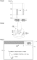
- the power range P1 of the engine 12 of the main propulsion device 1 and the power range P2 of the electric motor 23 of the auxiliary propulsion device 2 are now described with reference to FIG. 5 .
- the maximum and minimum values of the power range P1 of the engine 12 that drives the main propeller 10 are both larger than those of the electric motor 23 that drives the auxiliary propeller 20. Specifically, the maximum value (maximum output P10) of the power range P1 of the engine 12 is larger than the maximum value (maximum output P20) of the power range P2 of the electric motor 23. The minimum value (minimum output P11) of the power range P1 of the engine 12 is larger than the minimum value (minimum output P21) of the power range P2 of the electric motor 23.
- the upper limit value of the power range P1 of the engine 12 is limited when the main propulsion device 1 and the auxiliary propulsion device 2 are caused to cooperate with each other in the fixed point holding control, STAYPOINT (registered trademark) control.
- the lower limit value of the power range P2 of the electric motor 23 is limited when the main propulsion device 1 and the auxiliary propulsion device 2 are caused to cooperate with each other in the fixed point holding control. The details are described below.
- the joystick 3 shown in FIG. 6 is an operator to maneuver the marine vessel.
- the joystick 3 includes a main body 3a and a columnar stick 3b extending upward from the main body 3a.
- the stick 3b is a portion that is gripped by the user during maneuvering of the marine vessel.
- the main body 3a includes a joystick button 30, three buttons to start an automatic marine vessel maneuvering mode including a STAYPOINT (registered trademark) button 31a, a Fish Point (registered trademark) button 31b, and a drift button 31c, and a thrust adjustment operation button 32.
- the joystick button 30 receives operations to start and end a joystick mode. That is, the joystick button 30 switches between a normal state and a state (joystick mode) in which the joystick 3 is used to maneuver the marine vessel. In the normal state, the marine vessel is maneuvered using a remote control lever (not shown) to switch the shift state and adjust the engine speed, for example, and a steering wheel (not shown) to operate steering.
- the STAYPOINT (registered trademark) button 31a receives operations to start and end the STAYPOINT (registered trademark) control (fixed point holding control).
- the STAYPOINT (registered trademark) control (fixed point holding control) refers to an automatic marine vessel maneuvering control to maintain the orientation T1 of the bow 101a of the hull 101 at the target orientation T2 and maintain the position A1 of the hull 101 at the target point A2.
- the Fish Point button 31b receives operations to start and end a Fish Point control.
- the Fish Point control refers to an automatic marine vessel maneuvering control to direct the stern 101b (or the bow 101a) of the hull 101 to the target point by rotating the hull 101 and maintain the hull 101, the stern 101b (or the bow 101a) of which has been directed to the target point, at the target point by moving the hull 101 in the forward-rearward direction.
- the hull 101 does not move laterally in the Fish Point control.
- the drift button 31c receives operations to start and end a drift control.
- the drift control refers to an automatic marine vessel maneuvering control to move the hull 101 by receiving external forces including wind and water flow while maintaining the orientation of the bow 101a of the hull 101 at the target orientation by rotating the hull 101.
- the thrust adjustment operation button 32 receives an operation to adjust the level of the thrust magnitude of the marine vessel 100 (the main propulsion device 1 and the auxiliary propulsion device 2).
- the thrust adjustment operation button 32 includes a plus button 32a to increase the level of the thrust magnitude and a minus button 32b to decrease the level of the thrust magnitude.
- the marine vessel 100 moves in the tilting direction of the stick 3b while maintaining the orientation T1 of the bow 101a based on a tilting operation of the stick 3b by the user.
- the orientations of the bow 101a before and after the movement are parallel to each other.
- Predetermined calibration is performed in advance on the marine vessel 100 (controller 6) by a boat builder or the like such that the tilting direction of the stick 3b matches the actual moving direction of the hull 101.
- the marine vessel 100 rotates in the twisting direction of the stick 3b based on a twisting operation of the stick 3b by the user.
- the marine vessel 100 turns in the tilting and twisting directions of the stick 3b based on simultaneous tilting and twisting operations of the stick 3b by the user.
- the term "turn” indicates moving the hull 101 in the tilting direction of the stick 3b while gradually changing the orientation T1 of the bow 101a in the twisting direction of the stick 3b.
- the marine vessel 100 In the fixed point holding control, automatic marine vessel maneuvering is performed, and thus the stick 3b is not operated by the user. Furthermore, in the fixed point holding control, the marine vessel 100 only moves and rotates while maintaining the orientation T1 of the bow 101a, and does not turn.
- the display 4 includes a touch panel 4a.
- the display 4 displays a simplified model D of the hull 101 and a surrounding map M around the hull 101 including an obstacle O around the hull 101.
- the display 4 receives the setting of the target orientation T2 and the target point A2 based on a user's touch operation on the touch panel 4a.
- the setting of the target orientation T2 and the target point A2 may be performed via another operator such as a panel operator (not shown).
- the display 4 displays the target orientation T2 and the target point A2 set on the surrounding map M. Furthermore, the display 4 displays the current orientation T1 of the marine vessel 100 on the surrounding map M.
- the orientation sensor 5a shown in FIG. 1 measures the current orientation T1 of the marine vessel 100, which is the orientation (FWD) of the bow 101a of the marine vessel 100.
- the orientation sensor 5a is used to determine whether or not the current orientation T1 of the marine vessel 100 deviates from the target orientation T2 in the fixed point holding control, for example.
- the orientation sensor 5a includes an electronic compass.
- the position sensor 5b measures the current position A1 of the hull 101.
- the marine vessel 100 also acquires the current speed of the marine vessel 100 based on the time change of the current position A1 of the hull 101 measured by the position sensor 5b.
- the position sensor 5b includes a global positioning system (GPS) device.
- GPS global positioning system
- the controller 6 is a control circuit, for example, and includes a central processing unit (CPU).
- CPU central processing unit
- the controller 6 performs the fixed point holding control, STAYPOINT (registered trademark) control, to maintain the orientation T1 of the bow 101a of the hull 101 at the target orientation T2 and maintain the position A1 of the hull 101 at the target point A2 by causing the main propulsion device 1 and the auxiliary propulsion device 2 to cooperate with each other.
- STAYPOINT registered trademark
- the controller 6 corrects a deviation of the current orientation T1 of the bow 101a of the hull 101 from the target orientation T2 by rotating the hull 101 (brings the amount of deviation of the orientation closer to 0 by rotating the hull 101).
- the controller 6 calculates the amount of deviation of the orientation T1 of the bow 101a based on the measurement value of the orientation sensor 5a.
- the controller 6 corrects a deviation of the current position A1 of the hull 101 from the target point A2 by moving the hull 101 (brings the amount of deviation of the position closer to 0 by moving the hull 101).
- the controller 6 calculates the amount of deviation of the position based on the measurement value of the position sensor 5b.
- the term "move" in the fixed point holding control indicates changing the position A1 of the hull 101 while maintaining the orientation T1 of the bow 101a of the hull 101.
- the controller 6 performs a control to rotate the hull 101 to maintain the orientation T1 of the bow 101a at the target orientation T2 and a control to move the hull 101 to maintain the position A1 of the hull 101 at the target point A2 at different timings.
- the controller 6 limits the power range P1 of the engine 12 by matching the upper limit value of the power range P1 of the engine 12 with the maximum value (maximum output P20) of the power range P2 of the electric motor 23 while the main propulsion device 1 and the auxiliary propulsion device 2 are caused to cooperate with each other to move the hull 101 (see FIG. 5 ). Furthermore, the controller 6 limits the power range P2 of the electric motor 23 by matching the lower limit value of the power range P2 of the electric motor 23 with the minimum value (minimum output P11) of the power range P1 of the engine 12 while the main propulsion device 1 and the auxiliary propulsion device 2 are caused to cooperate with each other to move the hull 101 (see FIG. 5 ).
- the controller 6 sets a common power range for the engine 12 and the electric motor 23, in which the upper limit values of the outputs are the same as each other and the lower limit values of the outputs are the same as each other while the main propulsion device 1 and the auxiliary propulsion device 2 are caused to cooperate with each other to move the hull 101 (see FIG. 5 ).
- the controller 6 rotates the hull 101 by driving the auxiliary propeller 20 to generate a thrust from the auxiliary propulsion device 2 while the main propeller 10 that generates a thrust from the main propulsion device 1 is stopped when the hull 101 is rotated to maintain the orientation T1 of the bow 101a at the target orientation T2 in the fixed point holding control.
- the controller 6 rotates the hull 101 about the center of gravity of the hull 101 on the spot while holding the position A1 of the hull 101 in the fixed point holding control.
- the main propulsion device 1 engine outboard motor
- ⁇ 1 right-left rotatable angle range
- the controller 6 moves the hull 101 in the forward-rearward direction by driving the main propeller 10 while the auxiliary propeller 20 is stopped when the hull 101 is moved to maintain the position A1 of the hull 101 at the target point A2 in the fixed point holding control.
- the controller 6 moves the hull 101 laterally and diagonally while maintaining the orientation T1 of the bow 101a by simultaneously driving the main propeller 10 that generates a thrust from the main propulsion device 1 and the auxiliary propeller 20 that generates a thrust from the auxiliary propulsion device 2 when the hull 101 is moved to maintain the position A1 of the hull 101 at the target point A2 in the fixed point holding control.
- the controller 6 moves the hull 101 laterally and diagonally while maintaining the orientation T1 of the bow 101a by positioning an intersection I of the output vector V1 of the main propeller 10 and the output vector V2 of the auxiliary propeller 20 on a straight line SL passing through the center of gravity of the hull 101 and the target point A2 and setting, in a direction from the center of gravity to the target point A2, the direction T3 of the resultant force V3 of the output vector V1 of the main propeller 10 and the output vector V2 of the auxiliary propeller 20 that indicates the moving direction of the hull 101.
- the controller 6 causes the direction of the output vector V1 of the main propeller 10 and the direction of the output vector V2 of the auxiliary propeller 20 to be opposite to each other in the forward-rearward direction when the hull 101 is moved laterally or diagonally while the orientation T1 of the bow 101a is maintained.
- FIG. 11 A fixed point holding control process by the controller 6 of the marine propulsion system 102 is now described with reference to FIG. 11 .
- the control process starts from a state in which the amount of deviation of the current orientation T1 of the bow 101a from the target orientation T2 exceeds an orientation threshold and the amount of deviation of the current position A1 of the hull 101 from the target point A2 exceeds a position threshold.
- the control process to correct the orientation T1 of the bow 101a relatively greatly deviated from the target orientation T2 and the position A1 of the hull 101 relatively greatly deviated from the target point A2 is described below.
- step S1 the amount of deviation of the orientation T1 of the bow 101a from the target orientation T2 is calculated based on the measurement value of the orientation sensor 5a. Then, the process advances to step S2.
- step S2 the hull 101 is rotated by driving the auxiliary propeller 20 while the main propeller 10 is stopped. Then, the process advances to step S3.
- step S3 it is determined whether or not the amount of deviation of the orientation T1 of the bow 101a is equal to or less than the orientation threshold.
- the orientation T1 of the bow 101a substantially matches the target orientation T2.
- step S3 when the amount of deviation of the orientation T1 of the bow 101a is equal to or less than the orientation threshold, the process advances to step S4, and when the amount of deviation of the orientation T1 of the bow 101a is not equal to or less than the orientation threshold, the process returns to step S1.
- step S4 the amount of deviation of the position A1 of the hull 101 from the target point A2 is calculated based on the measurement value of the position sensor 5b. Then, the process advances to step S5.
- step S5 the hull 101 is moved toward the target point A2 while the orientation T1 of the bow 101a is maintained. At this time, when the hull 101 is moved in the forward-rearward direction, the hull 101 is moved by driving the main propeller 10 while the auxiliary propeller 20 is stopped. When the hull 101 is moved diagonally or laterally, the hull 101 is moved by simultaneously driving the auxiliary propeller 20 and the main propeller 10. Then, the process advances to step S6.
- step S6 it is determined whether or not the amount of deviation of the position A1 of the hull 101 is equal to or less than the position threshold.
- the position A1 of the hull 101 substantially matches the target point A2.
- step S6 when the amount of deviation of the position A1 of the hull 101 is equal to or less than the position threshold, the process proceeds to END, and when the amount of deviation of the position A1 of the hull 101 is not equal to or less than the position threshold, the process returns to step S4.
- the marine propulsion system 102 includes the controller 6 configured or programmed to perform the fixed point holding control, STAYPOINT (registered trademark) control, to maintain the orientation T1 of the bow 101a of the hull 101 at the target orientation T2 and maintain the position A1 of the hull 101 at the target point A2 by causing the main propulsion device 1 and the auxiliary propulsion device 2 to cooperate with each other.
- STAYPOINT registered trademark
- the main propulsion device 1 and the auxiliary propulsion device 2 are caused to cooperate with each other to flexibly rotate and move the hull 101 so as to maintain the orientation T1 of the bow 101a of the hull 101 at the target orientation T2 and maintain the position A1 of the hull 101 at the target point A2.
- the auxiliary propulsion device 2 includes the electric motor 23 to drive the auxiliary propeller 20 to generate a thrust. Accordingly, as compared with a case in which the main propulsion device 1 is driven and the auxiliary propulsion device 2 is an engine propulsion device, the amount of carbon dioxide emitted from the auxiliary propulsion device 2 is reduced.
- the hull 101 including the main propulsion device 1 and the auxiliary propulsion device 2 is held at a fixed point while environmental burdens associated with driving of the auxiliary propulsion device 2 are reduced as much as possible.
- the main propulsion device 1 is provided on the centerline ⁇ of the hull 101 in the right-left direction
- the auxiliary propulsion device 2 is provided to one side of the centerline of the hull 101 in the right-left direction. Accordingly, in the marine vessel 100 including the main propulsion device 1 provided on the centerline ⁇ of the hull 101 in the right-left direction, and the auxiliary propulsion device 2 provided to one side of the centerline of the hull 101 in the right-left direction, the main propulsion device 1 and the auxiliary propulsion device 2 are caused to cooperate with each other to flexibly rotate and move the hull 101, and thus the directions and magnitudes of the thrusts of the main propulsion device 1 and the auxiliary propulsion device 2 are adjusted in the fixed point holding control.
- the auxiliary propulsion device 2 has the right-left rotatable angle range ⁇ 2 to change the direction of the thrust larger than the right-left rotatable angle range ⁇ 1 of the main propulsion device 1, and the controller 6 is configured or programmed to rotate the hull 101 by driving the auxiliary propulsion device 2 in the fixed point holding control. Accordingly, the hull 101 is rotated (pivot-turned) by the electric motor-driven (electric) auxiliary propulsion device 2 that has the right-left rotatable angle range ⁇ 2 to change the direction of the thrust larger than the right-left rotatable angle range ⁇ 1 of the main propulsion device 1 such that a change in the position A1 of the hull 101 becomes smaller.
- the main propulsion device 1 includes the engine 12 to drive the main propeller 10 to generate a thrust, and the engine 12 has the maximum value and the minimum value of the power range P1 larger than the maximum value and the minimum value of the power range of the electric motor 23.
- the controller 6 is configured or programmed to limit the power range P1 of the engine 12 by matching the upper limit value of the power range P1 of the engine 12 with the maximum value of the power range P2 of the electric motor 23 while the main propulsion device 1 and the auxiliary propulsion device 2 are caused to cooperate with each other to move the hull 101, and to limit the power range P2 of the electric motor 23 by matching the lower limit value of the power range P2 of the electric motor 23 with the minimum value of the power range P1 of the engine 12 while the main propulsion device 1 and the auxiliary propulsion device 2 are caused to cooperate with each other to move the hull 101.
- the power range P1 of the engine 12 and the power range P2 of the electric motor 23 are adjusted to be equivalent to each other, and thus when the main propulsion device 1 and the auxiliary propulsion device 2 are caused to cooperate with each other, the output of the engine 12 and the output of the electric motor 23 are prevented from being out of balance.
- the controller 6 is configured or programmed to rotate the hull 101 by driving the auxiliary propeller 20 to generate a thrust from the auxiliary propulsion device 2 while the main propeller 10 that generates a thrust from the main propulsion device 1 is stopped when the hull 101 is rotated to maintain the orientation T1 of the bow 101a at the target orientation T2 in the fixed point holding control. Accordingly, the hull 101 is rotated only by the electric auxiliary propulsion device 2, and thus the hull 101 is quietly rotated. Furthermore, a thrust is generated only from the electric motor-driven (electric) auxiliary propulsion device 2 during rotation of the hull 101, and thus environmental burdens during rotation of the hull 101 are reduced.
- the controller 6 is configured or programmed to rotate the hull 101 about the center of gravity of the hull 101 on the spot while holding the position A1 of the hull 101. Accordingly, the hull 101 is rotated on the spot without changing the position A1 of the hull 101, and thus the accuracy of maintaining the target point A2 in the fixed point holding control is improved.
- the controller 6 is configured or programmed to, when the hull 101 is moved to maintain the position A1 of the hull 101 at the target point A2 in the fixed point holding control, move the hull 101 laterally or diagonally while maintaining the orientation T1 of the bow 101a by simultaneously driving the main propeller 10 to generate a thrust from the main propulsion device 1 and the auxiliary propeller 20 to generate a thrust from the auxiliary propulsion device 2, and move the hull 101 in the forward-rearward direction by driving the main propeller 10 while the auxiliary propeller 20 is stopped.
- the main propeller 10 and the auxiliary propeller 20 are simultaneously driven (caused to cooperate with each other) such that the hull 101 is moved laterally or diagonally while the orientation T1 of the bow 101a is maintained, and the hull 101 is moved in the forward-rearward direction by driving only the main propeller 10.
- the controller 6 is configured or programmed to move the hull 101 laterally or diagonally while maintaining the orientation T1 of the bow 101a by positioning the intersection I of the output vector V1 of the main propeller 10 and the output vector V2 of the auxiliary propeller 20 on the straight line SL passing through the center of gravity of the hull 101 and the target point A2 and setting, in the direction from the center of gravity to the target point A2, the direction T3 of the resultant force V3 of the output vector V1 of the main propeller 10 and the output vector V2 of the auxiliary propeller 20 that indicates the moving direction of the hull 101.
- the hull 101 is moved laterally or diagonally while the orientation T1 of the bow 101a is maintained.
- the controller 6 is configured or programmed to cause the direction of the output vector V1 of the main propeller 10 and the direction of the output vector V2 of the auxiliary propeller 20 to be opposite to each other in the forward-rearward direction when the hull 101 is moved laterally or diagonally while the orientation T1 of the bow 101a is maintained. Accordingly, the direction of the output vector V1 of the main propeller 10 and the direction of the output vector V2 of the auxiliary propeller 20 are opposite to each other, and thus the hull 101 is easily moved laterally or diagonally while the orientation T1 of the bow 101a is maintained.
- the controller 6 is configured or programmed to perform a control to rotate the hull 101 to maintain the orientation T1 of the bow 101a at the target orientation T2 and a control to move the hull 101 to maintain the position A1 of the hull 101 at the target point A2 at the different timings in the fixed point holding control. Accordingly, rotating the hull 100 to maintain the orientation T1 of the bow 101a at the target orientation T2 and moving the hull 101 to maintain the position A1 of the hull 101 at the target point A2 are separated from each other such that a change in the position A1 of the hull 101 during rotation of the hull 101 is significantly reduced or prevented, and a change in the orientation T1 of the bow 101a during movement of the hull 101 is significantly reduced or prevented.
- the main propulsion device 1 is an engine outboard motor including the engine 12 to drive the main propeller to generate a thrust and provided on the centerline ⁇ of the hull 101 in the right-left direction
- the auxiliary propulsion device 2 is an electric outboard motor including the electric motor 23 to drive the auxiliary propeller 20 and provided to one side of the centerline of the hull 101 in the right-left direction. Accordingly, environmental burdens are reduced due to driving of the electric outboard motor, and the hull 101 including the engine outboard motor and the electric outboard motor is held at a fixed point.
- process operations performed by the controller are described using a flowchart in a flow-driven manner in which processes are performed in order along a process flow for the convenience of illustration in preferred embodiments described above, the present teaching is not restricted to this.
- the process operations performed by the controller may alternatively be performed in an event-driven manner in which the processes are performed on an event basis.
- the process operations performed by the controller may be performed in a complete event-driven manner or in a combination of an event-driven manner and a flow-driven manner.
- the marine propulsion system preferably includes only one main propulsion device in preferred embodiments described above, the present teaching is not restricted to this.
- the marine propulsion system may alternatively include a plurality of main propulsion devices.
- the marine propulsion system preferably includes only one auxiliary propulsion device in preferred embodiments described above, the present teaching is not restricted to this.
- the marine propulsion system may alternatively include a plurality of auxiliary propulsion devices.
- main thruster of the main propulsion device is preferably the main propeller in preferred embodiments described above, the present teaching is not restricted to this.
- the main thruster of the main propulsion device may alternatively be a jet that generates a thrust by jetting water.
- auxiliary thruster of the auxiliary propulsion device is preferably the auxiliary propeller in preferred embodiments described above, the present teaching is not restricted to this.
- the auxiliary thruster of the auxiliary propulsion device may alternatively be a jet that generates a thrust by jetting water.
- main propulsion device is preferably provided on the centerline of the hull in the right-left direction in preferred embodiments described above, the present teaching is not restricted to this. In the present teaching, the main propulsion device may alternatively be shifted from the centerline of the hull in the right-left direction.
- the main propulsion device preferably includes the engine as a drive source for the main propeller in preferred embodiments described above, the present teaching is not restricted to this.
- the main propulsion device may alternatively include an electric motor as a drive source for the main propeller.
- main propulsion device and the auxiliary propulsion device are preferably outboard motors in preferred embodiments described above, the present teaching is not restricted to this.
- the main propulsion device and the auxiliary propulsion device may alternatively be inboard-outboard motors, for example.
Landscapes
- Chemical & Material Sciences (AREA)
- Engineering & Computer Science (AREA)
- Combustion & Propulsion (AREA)
- Mechanical Engineering (AREA)
- Ocean & Marine Engineering (AREA)
- Control Of Position, Course, Altitude, Or Attitude Of Moving Bodies (AREA)
- Control Of Vehicle Engines Or Engines For Specific Uses (AREA)
Applications Claiming Priority (1)
| Application Number | Priority Date | Filing Date | Title |
|---|---|---|---|
| JP2021180206A JP2023068836A (ja) | 2021-11-04 | 2021-11-04 | 船舶推進システムおよび船舶 |
Publications (1)
| Publication Number | Publication Date |
|---|---|
| EP4177155A1 true EP4177155A1 (fr) | 2023-05-10 |
Family
ID=84245881
Family Applications (1)
| Application Number | Title | Priority Date | Filing Date |
|---|---|---|---|
| EP22205548.5A Pending EP4177155A1 (fr) | 2021-11-04 | 2022-11-04 | Système de propulsion marine |
Country Status (3)
| Country | Link |
|---|---|
| US (1) | US20230140720A1 (fr) |
| EP (1) | EP4177155A1 (fr) |
| JP (1) | JP2023068836A (fr) |
Families Citing this family (2)
| Publication number | Priority date | Publication date | Assignee | Title |
|---|---|---|---|---|
| JP2023068785A (ja) * | 2021-11-04 | 2023-05-18 | ヤマハ発動機株式会社 | 船舶推進システムおよび船舶 |
| JP2024005605A (ja) * | 2022-06-30 | 2024-01-17 | ヤマハ発動機株式会社 | 船舶を制御するためのシステム及び方法 |
Citations (5)
| Publication number | Priority date | Publication date | Assignee | Title |
|---|---|---|---|---|
| JP2000344193A (ja) | 1999-06-01 | 2000-12-12 | Fuji Royal:Kk | 自動復帰航行装置 |
| EP3000718A1 (fr) * | 2014-09-26 | 2016-03-30 | Yamaha Hatsudoki Kabushiki Kaisha | Dispositif de propulsion électrique |
| US20180015994A1 (en) * | 2014-12-22 | 2018-01-18 | Furuno Electric Co., Ltd. | Mobile object control device, mobile object control method, and mobile object control program |
| US20190179318A1 (en) * | 2017-12-11 | 2019-06-13 | Garmin Switzerland Gmbh | Multiple motor control system for navigating a marine vessel |
| EP3722201A1 (fr) * | 2019-04-02 | 2020-10-14 | Yamaha Hatsudoki Kabushiki Kaisha | Système de propulsion de récipient et récipient |
Family Cites Families (8)
| Publication number | Priority date | Publication date | Assignee | Title |
|---|---|---|---|---|
| US4573930A (en) * | 1979-08-20 | 1986-03-04 | Queen Charles L | Steering mechanisms for outboard motor |
| US8272906B2 (en) * | 2008-12-17 | 2012-09-25 | Yamaha Hatsudoki Kabushiki Kaisha | Outboard motor control device and marine vessel including the same |
| EP2727819B1 (fr) * | 2011-06-28 | 2019-09-04 | Yanmar Co., Ltd. | Dispositif de gouverne de bateau et procédé de gouverne de bateau |
| JP2015116847A (ja) * | 2013-12-16 | 2015-06-25 | ヤマハ発動機株式会社 | 船舶推進システムおよびそれを備えた船舶 |
| JP7064574B2 (ja) * | 2018-03-23 | 2022-05-10 | 本田技研工業株式会社 | 船舶の推進器の制御装置、船舶の推進器の制御方法、及び船舶の推進器の制御プログラム |
| JP7117895B2 (ja) * | 2018-05-15 | 2022-08-15 | ヤマハ発動機株式会社 | 船舶、及び船舶の操船システム |
| JP2024060163A (ja) * | 2022-10-19 | 2024-05-02 | ヤマハ発動機株式会社 | 船舶推進システムおよび船舶 |
| JP2024060160A (ja) * | 2022-10-19 | 2024-05-02 | ヤマハ発動機株式会社 | 船舶推進システムおよび船舶 |
-
2021
- 2021-11-04 JP JP2021180206A patent/JP2023068836A/ja active Pending
-
2022
- 2022-10-21 US US17/970,619 patent/US20230140720A1/en active Pending
- 2022-11-04 EP EP22205548.5A patent/EP4177155A1/fr active Pending
Patent Citations (5)
| Publication number | Priority date | Publication date | Assignee | Title |
|---|---|---|---|---|
| JP2000344193A (ja) | 1999-06-01 | 2000-12-12 | Fuji Royal:Kk | 自動復帰航行装置 |
| EP3000718A1 (fr) * | 2014-09-26 | 2016-03-30 | Yamaha Hatsudoki Kabushiki Kaisha | Dispositif de propulsion électrique |
| US20180015994A1 (en) * | 2014-12-22 | 2018-01-18 | Furuno Electric Co., Ltd. | Mobile object control device, mobile object control method, and mobile object control program |
| US20190179318A1 (en) * | 2017-12-11 | 2019-06-13 | Garmin Switzerland Gmbh | Multiple motor control system for navigating a marine vessel |
| EP3722201A1 (fr) * | 2019-04-02 | 2020-10-14 | Yamaha Hatsudoki Kabushiki Kaisha | Système de propulsion de récipient et récipient |
Also Published As
| Publication number | Publication date |
|---|---|
| JP2023068836A (ja) | 2023-05-18 |
| US20230140720A1 (en) | 2023-05-04 |
Similar Documents
| Publication | Publication Date | Title |
|---|---|---|
| EP1775212A2 (fr) | Embarcation et méthode pour la manoeuvre | |
| EP1775211A2 (fr) | Embarcation et méthode pour le positionnement | |
| EP4177155A1 (fr) | Système de propulsion marine | |
| EP4365074B9 (fr) | Système de propulsion d'embarcation, embarcation et procédé de commande de propulsion d'embarcation | |
| EP4177154A1 (fr) | Système de propulsion marine | |
| US12528572B2 (en) | Watercraft propulsion system, and watercraft | |
| EP4516658A1 (fr) | Système de propulsion marine, procédé de commande associé et navire | |
| EP4177152A1 (fr) | Système de propulsion marine | |
| EP4177153B1 (fr) | Système de propulsion marine | |
| US20250236378A1 (en) | Boat control system and boat | |
| US11573087B1 (en) | Boat maneuvering control method for boat and boat maneuvering control system for boat | |
| EP4206071B1 (fr) | Système de propulsion marine | |
| US20240132190A1 (en) | Watercraft propulsion system, and watercraft | |
| EP4201802B1 (fr) | Système de propulsion marine et navire marin doté d'un système de propulsion marine | |
| EP4177150A1 (fr) | Système de propulsion marine et navire marin | |
| US20250236379A1 (en) | Boat control system and boat | |
| US20240150000A1 (en) | Watercraft propulsion system, and watercraft including the watercraft propulsion system | |
| US20250050997A1 (en) | Marine propulsion system, control method therefor, and marine vessel | |
| US12013699B1 (en) | Boat maneuvering control method for boat and boat maneuvering control system for boat | |
| US20250236380A1 (en) | Boat control system and boat | |
| US20250050996A1 (en) | Marine propulsion system, control method therefor, and marine vessel | |
| JP2024101415A (ja) | 操船システムおよびそれを備える船舶 |
Legal Events
| Date | Code | Title | Description |
|---|---|---|---|
| PUAI | Public reference made under article 153(3) epc to a published international application that has entered the european phase |
Free format text: ORIGINAL CODE: 0009012 |
|
| STAA | Information on the status of an ep patent application or granted ep patent |
Free format text: STATUS: THE APPLICATION HAS BEEN PUBLISHED |
|
| AK | Designated contracting states |
Kind code of ref document: A1 Designated state(s): AL AT BE BG CH CY CZ DE DK EE ES FI FR GB GR HR HU IE IS IT LI LT LU LV MC ME MK MT NL NO PL PT RO RS SE SI SK SM TR |
|
| P01 | Opt-out of the competence of the unified patent court (upc) registered |
Effective date: 20230713 |
|
| STAA | Information on the status of an ep patent application or granted ep patent |
Free format text: STATUS: REQUEST FOR EXAMINATION WAS MADE |
|
| 17P | Request for examination filed |
Effective date: 20231109 |
|
| RBV | Designated contracting states (corrected) |
Designated state(s): AL AT BE BG CH CY CZ DE DK EE ES FI FR GB GR HR HU IE IS IT LI LT LU LV MC ME MK MT NL NO PL PT RO RS SE SI SK SM TR |
|
| STAA | Information on the status of an ep patent application or granted ep patent |
Free format text: STATUS: EXAMINATION IS IN PROGRESS |
|
| 17Q | First examination report despatched |
Effective date: 20240730 |