EP4177360A1 - Procédé et système de commande de soufflage de convertisseur - Google Patents
Procédé et système de commande de soufflage de convertisseur Download PDFInfo
- Publication number
- EP4177360A1 EP4177360A1 EP21832549.6A EP21832549A EP4177360A1 EP 4177360 A1 EP4177360 A1 EP 4177360A1 EP 21832549 A EP21832549 A EP 21832549A EP 4177360 A1 EP4177360 A1 EP 4177360A1
- Authority
- EP
- European Patent Office
- Prior art keywords
- temperature
- converter
- molten iron
- blowing
- charged
- Prior art date
- Legal status (The legal status is an assumption and is not a legal conclusion. Google has not performed a legal analysis and makes no representation as to the accuracy of the status listed.)
- Pending
Links
Images
Classifications
-
- C—CHEMISTRY; METALLURGY
- C21—METALLURGY OF IRON
- C21C—PROCESSING OF PIG-IRON, e.g. REFINING, MANUFACTURE OF WROUGHT-IRON OR STEEL; TREATMENT IN MOLTEN STATE OF FERROUS ALLOYS
- C21C5/00—Manufacture of carbon-steel, e.g. plain mild steel, medium carbon steel or cast steel or stainless steel
- C21C5/28—Manufacture of steel in the converter
- C21C5/30—Regulating or controlling the blowing
-
- C—CHEMISTRY; METALLURGY
- C21—METALLURGY OF IRON
- C21C—PROCESSING OF PIG-IRON, e.g. REFINING, MANUFACTURE OF WROUGHT-IRON OR STEEL; TREATMENT IN MOLTEN STATE OF FERROUS ALLOYS
- C21C5/00—Manufacture of carbon-steel, e.g. plain mild steel, medium carbon steel or cast steel or stainless steel
- C21C5/28—Manufacture of steel in the converter
- C21C5/42—Constructional features of converters
- C21C5/46—Details or accessories
- C21C5/466—Charging device for converters
-
- C—CHEMISTRY; METALLURGY
- C21—METALLURGY OF IRON
- C21C—PROCESSING OF PIG-IRON, e.g. REFINING, MANUFACTURE OF WROUGHT-IRON OR STEEL; TREATMENT IN MOLTEN STATE OF FERROUS ALLOYS
- C21C5/00—Manufacture of carbon-steel, e.g. plain mild steel, medium carbon steel or cast steel or stainless steel
- C21C5/28—Manufacture of steel in the converter
- C21C5/42—Constructional features of converters
- C21C5/46—Details or accessories
- C21C5/4673—Measuring and sampling devices
-
- C—CHEMISTRY; METALLURGY
- C21—METALLURGY OF IRON
- C21C—PROCESSING OF PIG-IRON, e.g. REFINING, MANUFACTURE OF WROUGHT-IRON OR STEEL; TREATMENT IN MOLTEN STATE OF FERROUS ALLOYS
- C21C7/00—Treating molten ferrous alloys, e.g. steel, not covered by groups C21C1/00 - C21C5/00
- C21C7/04—Removing impurities by adding a treating agent
-
- F—MECHANICAL ENGINEERING; LIGHTING; HEATING; WEAPONS; BLASTING
- F27—FURNACES; KILNS; OVENS; RETORTS
- F27B—FURNACES, KILNS, OVENS OR RETORTS IN GENERAL; OPEN SINTERING OR LIKE APPARATUS
- F27B1/00—Shaft or like vertical or substantially vertical furnaces
- F27B1/10—Details, accessories or equipment specially adapted for furnaces of these types
- F27B1/28—Arrangements of monitoring devices, of indicators, of alarm devices
-
- F—MECHANICAL ENGINEERING; LIGHTING; HEATING; WEAPONS; BLASTING
- F27—FURNACES; KILNS; OVENS; RETORTS
- F27D—DETAILS OR ACCESSORIES OF FURNACES, KILNS, OVENS OR RETORTS, IN SO FAR AS THEY ARE OF KINDS OCCURRING IN MORE THAN ONE KIND OF FURNACE
- F27D19/00—Arrangements of controlling devices
-
- F—MECHANICAL ENGINEERING; LIGHTING; HEATING; WEAPONS; BLASTING
- F27—FURNACES; KILNS; OVENS; RETORTS
- F27D—DETAILS OR ACCESSORIES OF FURNACES, KILNS, OVENS OR RETORTS, IN SO FAR AS THEY ARE OF KINDS OCCURRING IN MORE THAN ONE KIND OF FURNACE
- F27D21/00—Arrangement of monitoring devices; Arrangement of safety devices
- F27D21/0014—Devices for monitoring temperature
-
- F—MECHANICAL ENGINEERING; LIGHTING; HEATING; WEAPONS; BLASTING
- F27—FURNACES; KILNS; OVENS; RETORTS
- F27D—DETAILS OR ACCESSORIES OF FURNACES, KILNS, OVENS OR RETORTS, IN SO FAR AS THEY ARE OF KINDS OCCURRING IN MORE THAN ONE KIND OF FURNACE
- F27D21/00—Arrangement of monitoring devices; Arrangement of safety devices
- F27D21/02—Observation or illuminating devices
-
- C—CHEMISTRY; METALLURGY
- C21—METALLURGY OF IRON
- C21C—PROCESSING OF PIG-IRON, e.g. REFINING, MANUFACTURE OF WROUGHT-IRON OR STEEL; TREATMENT IN MOLTEN STATE OF FERROUS ALLOYS
- C21C2300/00—Process aspects
- C21C2300/06—Modeling of the process, e.g. for control purposes; CII
-
- F—MECHANICAL ENGINEERING; LIGHTING; HEATING; WEAPONS; BLASTING
- F27—FURNACES; KILNS; OVENS; RETORTS
- F27D—DETAILS OR ACCESSORIES OF FURNACES, KILNS, OVENS OR RETORTS, IN SO FAR AS THEY ARE OF KINDS OCCURRING IN MORE THAN ONE KIND OF FURNACE
- F27D19/00—Arrangements of controlling devices
- F27D2019/0003—Monitoring the temperature or a characteristic of the charge and using it as a controlling value
-
- F—MECHANICAL ENGINEERING; LIGHTING; HEATING; WEAPONS; BLASTING
- F27—FURNACES; KILNS; OVENS; RETORTS
- F27D—DETAILS OR ACCESSORIES OF FURNACES, KILNS, OVENS OR RETORTS, IN SO FAR AS THEY ARE OF KINDS OCCURRING IN MORE THAN ONE KIND OF FURNACE
- F27D21/00—Arrangement of monitoring devices; Arrangement of safety devices
- F27D21/02—Observation or illuminating devices
- F27D2021/026—Observation or illuminating devices using a video installation
Definitions
- the present invention relates to a converter blowing control method and a converter blowing control system for controlling the temperature and component concentration of molten steel at the end of blowing to target values.
- the converter operation is a steelmaking process of obtaining molten steel by supplying oxygen to main raw materials including molten iron, scrap, or the like charged into a converter to perform oxidation refining (blowing).
- blowing control combining static control and dynamic control is performed in order to control the temperature and component concentration such as carbon concentration of molten steel at the end of blowing (blowing stop) to target values.
- static control a mathematical model based on heat balance and material balance is used to determine, before the start of blowing, an amount of oxygen to be supplied and an amount of a cooling material or rising heat material to be charged necessary to control the temperature and component concentration of the molten steel to target values.
- the dynamic control the temperature and component concentration of molten metal are measured using a sublance during blowing, and the amount of oxygen to be supplied and the amount of a cooling material or rising heat material to be charged determined in the static control are corrected based on a mathematical model based on the heat balance and the material balance and a reaction model. Then, in the dynamic control, the amount of oxygen to be supplied and the amount of a cooling material or rising heat material to be charged before blowing stop are finally determined and controlled.
- the mathematical model used for the static control includes two types of calculation: heat balance calculation and oxygen balance calculation.
- heat balance calculation the amount of a cooling material or rising heat material to be charged is calculated such that the sum of heat input into the converter and the sum of heat output from the converter are equal.
- a formula used for the heat balance calculation includes a heat input determination term, a heat output determination term, a cooling term or a rising heat term, an error term, and a temperature correction term by an operator.
- Patent Literature 1 discloses a method of predicting, based on a cooling curve obtained from a surface temperature of an inner clad refractory of a converter measured by a radiation thermometer and time information, an amount of temperature drop of molten steel in the subsequent blowing and incorporating the amount into heat balance calculation in static control.
- Patent Literature 2 discloses a method for utilizing exhaust gas information to estimate a decarbonize-oxygen efficiency attenuation constant and a maximum decarbonize-oxygen efficiency that characterize decarburization characteristics during blowing, and using the estimation result to estimate the temperature and carbon concentration of the molten steel.
- the control accuracy of the temperature of the molten steel in blowing stop is increased.
- the control accuracy of the temperature of the molten steel in blowing stop still did not reach a satisfactory level.
- the present invention has been made in view of the above issues, and an object thereof is to provide a converter blowing control method and a converter blowing control system capable of accurately controlling the temperature of molten steel at the end of blowing to a target value.
- a converter blowing control method includes: calculating, by heat balance calculation and material balance calculation, an amount of oxygen to be supplied and an amount of a cooling material or a rising heat material to be charged for controlling a temperature and a component concentration of molten steel at end of blowing in a converter to target values; and controlling the blowing in the converter based on the calculated amount of oxygen to be supplied and the calculated amount of a cooling material or a rising heat material to be charged, wherein a temperature of molten iron is used as a raw material for blowing, which is a target of the heat balance calculation, is used as a charged molten iron temperature used in the heat balance calculation, the temperature of molten iron being measured during a period when the molten iron is charged into the converter.
- a converter blowing control method includes: sequentially estimating a temperature and a component concentration of molten metal at progress of blowing by sequentially performing heat balance calculation and material balance calculation during the blowing based on operation conditions and a measured value of a converter obtained at start of and during the blowing in the converter; and controlling the blowing in the converter based on the estimated temperature and the estimated component concentration of the molten metal, wherein a temperature of molten iron used as a raw material for blowing, which is a target of the heat balance calculation, is used as a charged molten iron temperature used in the heat balance calculation, the temperature of molten iron being measured during a period when the molten iron is charged into the converter.
- a temperature of molten iron used as a raw material for blowing which is a target of the heat balance calculation, may be used as the charged molten iron temperature used in the heat balance calculation, the temperature of molten iron being measured by a non-contact optical method when the molten iron flows into the converter from a molten iron holding container.
- the non-contact optical method may be a method of measuring an emission spectrum emitted from the molten iron to calculate a temperature of the molten iron from a radiation energy ratio of two different wavelengths selected from the measured emission spectrum.
- ⁇ 1 and ⁇ 2 may be both in a range of 400 nm to 1000 nm and an absolute value of a difference between ⁇ 1 and ⁇ 2 is 50 nm or more and 600 nm or less, where the two different wavelengths are ⁇ 1 and ⁇ 2 (> ⁇ 1).
- ⁇ 1 and ⁇ 2 may be both in a range of 400 nm to 1000 nm and an absolute value of a difference between ⁇ 1 and ⁇ 2 is 200 nm or more and 600 nm or less, where the two different wavelengths are ⁇ 1 and ⁇ 2 (> ⁇ 1).
- a measured value of the temperature of the molten iron may be corrected based on a predetermined ratio of emissivity of emission spectra of the two different wavelengths.
- a converter blowing control system includes: a temperature measuring device configured to optically measure, as a charged molten iron temperature, a temperature of molten iron used as a raw material for blowing in a converter during a period when the molten iron is charged into the converter; a computer configured to use the charged molten iron temperature measured by the temperature measuring device to calculate, by heat balance calculation and material balance calculation, an amount of oxygen to be supplied to the converter and an amount of a cooling material or a rising heat material to be charged into the converter for controlling a temperature and a component concentration of molten steel at end of the blowing in the converter to target values; and a control device configured to control the blowing in the converter based on the amount of oxygen to be supplied to the converter and the amount of a cooling material or a rising heat material to be charged into the converter calculated by the computer.
- a converter blowing control system includes: a spectroscopic camera configured to measure temperature information measured by two-color thermometer of molten iron used as a raw material for blowing in a converter during a period when the molten iron is charged into the converter; a first computer configured to use the temperature information measured by two-color thermometer measured by the spectroscopic camera to calculate a temperature of the molten iron as a charged molten iron temperature; a second computer configured to use the charged molten iron temperature calculated by the first computer to calculate, by heat balance calculation and material balance calculation, an amount of oxygen to be supplied to the converter and an amount of a cooling material or a rising heat material to be charged into the converter for controlling a temperature and a component concentration of molten steel at end of the blowing in the converter to target values; and a control device configured to control the blowing in the converter based on the amount of oxygen to be supplied to the converter and the amount of a cooling material or a rising heat material to be charged into the converter calculated by the
- a converter blowing control system includes: a temperature measuring device configured to optically measure, as a charged molten iron temperature, a temperature of molten iron used as a raw material for blowing in a converter during a period when the molten iron is charged into the converter; a computer configured to use the charged molten iron temperature measured by the temperature measuring device to sequentially calculate a temperature of molten steel during the blowing; and a control device configured to control the blowing in the converter based on the temperature of the molten steel during the blowing calculated by the computer.
- a converter blowing control system includes: a spectroscopic camera configured to measure temperature information measured by two-color thermometer of molten iron used as a raw material for blowing in a converter during a period when the molten iron is charged into the converter; a first computer configured to use the temperature information measured by two-color thermometer measured by the spectroscopic camera to calculate a temperature of the molten iron as a charged molten iron temperature; a second computer configured to use the charged molten iron temperature calculated by the first computer to sequentially calculate a temperature of molten steel during the blowing; and a control device configured to control the blowing in the converter based on the temperature of the molten steel during the blowing calculated by the second computer.
- the temperature of molten steel at the end of blowing can be accurately controlled to a target value.
- blowing control combining static control and dynamic control is performed in order to control the temperature and component concentration such as carbon concentration of molten steel at the end of blowing (blowing stop) to target values.
- static control a mathematical model based on heat balance calculation and material balance calculation is used to determine, before the start of blowing, an amount of oxygen to be supplied and an amount of a cooling material and rising heat material to be charged (hereinafter, referred to as a cooling material and so on) necessary to control the temperature and component concentration of the molten steel to target values.
- the blowing is started and progressed based on the determined amount of oxygen to be supplied and the determined amount of a cooling material and so on to be charged, and the blowing is continued for a certain period of time (for example, a time point at which 80 to 90% of the amount of oxygen to be supplied calculated in the static control is blown, and the like), and then the temperature and component concentration of the molten metal are measured using a sublance.
- a mathematical model based on the temperature and component concentration of the molten metal measured using the sublance, the heat balance, the material balance, and the reaction model is used to correct the amount of oxygen to be supplied and the amount of a cooling material and so on to be charged that are determined in the static control, and the amount of oxygen to be supplied and the amount of a cooling material and so on to be charged before blowing stop are determined finally.
- a calculation formula used for the heat balance calculation in the static control includes, for example, a heat input determination term, a heat output determination term, a cooling term or a temperature-rising term, an error term, and a temperature correction term by an operator.
- the heat input determination term includes a term representing sensible heat of the molten iron to be charged.
- the sensible heat of the molten iron to be charged is calculated by a formula of (specific heat of molten iron) ⁇ (mass of molten iron to be charged) ⁇ (temperature of molten iron to be charged).
- specific heat of molten iron a physical property value described in a handbook or the like is used.
- mass of molten iron to be charged for example, a difference between the weight of a charging ladle (molten iron holding container) filled with the molten iron measured by a load cell or the like before the molten iron is charged and the weight of an empty charging ladle measured by a load cell or the like after the molten iron is charged is used.
- temperature of molten iron to be charged charged molten iron temperature
- a value measured by immersing a thermocouple in molten iron filled in the charging ladle is used, for example.
- the inventors of the present invention found that a reason why the control accuracy of temperature of molten steel in blowing stop is not increased is that a value of the sensible heat of the molten iron to be charged is inaccurate in the heat balance calculation in the static control and the dynamic control.
- the inventors of the present invention found that, in a case where the sensible heat of the molten iron to be charged is calculated, it is not always appropriate to use a measured value of the temperature of the molten iron described above.
- the temperature of molten iron is measured after the molten iron is charged into a charging ladle and slag is removed.
- an elapsed time before the molten iron is charged into the converter greatly varies depending on the operation state of the converter and steelmaking process after the converter.
- the molten iron is immediately charged into the converter to start blowing in some cases, or after the temperature of the molten iron is measured, it may be forced to wait until the molten iron is charged into the converter in a state where the molten iron is filled in the charging ladle as it is. That is, since an amount of temperature drop of the molten iron in a period from when the temperature of the molten iron is measured to when the molten iron is charged into the converter is different, the actual charged molten iron temperature is also different.
- the temperature distribution of the molten iron occurs in the depth direction of the charging ladle due to heat convection.
- the depth of a molten iron bath when filled with molten iron is on the order of several meters, whereas the depth of immersion of the thermocouple at the time of temperature measurement is several tens of centimeters.
- the state of the charging ladle used also affects the amount of temperature drop of the molten iron in the period from when the temperature of the molten iron is measured to when the molten iron is charged into the converter.
- a charging ladle having a high ratio of a ladle filled time time in the state of being filled with the molten iron within a certain period
- a charging ladle having a low ratio of the ladle filled time has a large amount of temperature drop of the molten iron.
- one of the converters performs a desiliconization treatment or a dephosphorization treatment (a desiliconization/dephosphorization furnace), and the other converter performs a decarburization treatment (a decarburization furnace).
- a desiliconization/dephosphorization furnace performs a decarburization treatment
- molten iron that has been treated in the desiliconization/dephosphorization furnace is received in a charging ladle on standby under the furnace, and the molten iron received in the charging ladle is charged into the decarburization furnace to perform a decarburization treatment.
- the static control and the dynamic control described above are also performed in the decarburization treatment, and as the charged molten iron temperature in the heat balance calculation, a molten iron temperature measured in the converter at the end of the desiliconization/dephosphorization treatment or during tapping, or a temperature obtained by correcting the molten iron temperature measured in the converter at the end of the desiliconization/dephosphorization treatment or during tapping with the amount of temperature drop of the molten iron during tapping, or the like is used.
- a time from tapping to charging greatly varies depending on the operation state.
- the inventors of the present invention used, as the charged molten iron temperature used for heat balance calculation, a temperature of the molten iron measured during a period in which the molten iron used as a raw material for blowing, which is a target of the heat balance calculation, is charged into the converter. This increases the accuracy of heat balance calculation as compared with the related art and enables the temperature of the molten steel to be accurately controlled to a target value.
- the temperature of the molten iron measured by a non-contact optical method when the molten iron used as a raw material for blowing, which is a target of the heat balance calculation, flows into the converter from the charging ladle.
- the temperature of the molten iron is measured at this timing to obtain a measured value after the influence of the waiting time in the charging ladle or the like is reflected, so that the problem described above is solved.
- a method of measuring by immersing a thermocouple or the like in an injection flow when the molten iron flows into the converter from the charging ladle is possible; however, large-scale equipment is required to immerse the thermocouple in the injection flow. Accordingly, it is preferable to use a non-contact optical method with which the temperature can be measured more easily.
- non-contact optical method examples include a temperature measurement method using a two-color thermometer, a radiation thermometer, a thermoviewer, or the like.
- a temperature is measured by the non-contact optical method, it may be difficult to measure the temperature accurately because slag floats on the bath surface in the molten iron in a stationary state filled in the charging ladle.
- measurement is performed on an injection flow at the time of flowing into the converter from the charging ladle, the surface of the molten iron is partly exposed, so that more accurate measurement can be performed.
- a method of measuring an emission spectrum emitted from the molten iron and calculating a temperature from a radiation energy ratio of two different wavelengths selected from the obtained emission spectrum that is, a method using a two-color thermometer is more preferable.
- the emissivity of the injection flow at the time of flowing into the converter from the charging ladle which is a target of the temperature measurement in the present invention, varies depending on the measurement conditions.
- the two different wavelengths are ⁇ 1 and ⁇ 2 ( ⁇ 1 ⁇ ⁇ 2)
- ⁇ 1 and ⁇ 2 are both in the range of 400 nm to 1000 nm and the absolute value of the difference between ⁇ 1 and ⁇ 2 is 50 nm or more and 600 nm or less.
- a measurement error occurs in a case where the emissivity of two emission spectra having different wavelengths do not vary while maintaining a proportional relationship with each other.
- ⁇ 1 and ⁇ 2 are preferable to select both ⁇ 1 and ⁇ 2 within the range of 400 nm to 1000 nm.
- the wavelength is less than 400 nm, it is difficult for an ordinary spectroscopic camera to detect radiation energy because the wavelength is short.
- the wavelength exceeds 1000 nm, the wavelength is long, and thus the influence of variations in emissivity ratio increases.
- the absolute value of the difference between ⁇ 1 and ⁇ 2 is preferably 50 nm or more and 600 nm or less.
- the absolute value of the difference between ⁇ 1 and ⁇ 2 is less than 50 nm, the wavelengths of ⁇ 1 and ⁇ 2 are close to each other, and thus, it is difficult to perform spectroscopy with an ordinary spectroscopic camera.
- the absolute value of the difference between ⁇ 1 and ⁇ 2 exceeds 600 nm, one wavelength is inevitably selected from the condition of long wavelength, and the influence of variations in emissivity ratio increases because of the long wavelength.
- the absolute value of the difference between ⁇ 1 and ⁇ 2 is 200 nm or more and 600 nm or less, the influence of variations in emissivity ratio R is reduced, which is more preferable.
- the emissivity ratio R may be determined in advance based on experiments or literature values, and the measured value of the temperature of the molten iron may be corrected with the emissivity ratio R determined in advance. However, even if the measured value of the temperature of the molten iron is corrected with the predetermined emissivity ratio R in order to reduce measurement errors, a measurement error may occur.
- the intensity of light emitted from the molten iron is attenuated by soot and smoke generated by a reaction between the molten iron and oxygen in the atmosphere at the time of molten iron charging.
- the attenuation rate of emitted light varies depending on the measured wavelength
- the radiation energy ratio I( ⁇ 1)/I( ⁇ 2) between ⁇ 1 and ⁇ 2 changes, which causes a measurement error.
- the soot and smoke it is difficult to reduce the soot and smoke, and the concentration and occurrence frequency thereof cannot be predicted and thus it is difficult to take the influence of the soot and smoke into consideration with high accuracy by correction in advance.
- sparks, flames, and the like generated while the molten iron is charged may also have an influence similar to the soot and smoke.
- the inventors of the present invention further studied measures for reducing the influence of the soot and smoke described above and enabling more accurate temperature measurement. Specifically, the inventors of the present invention focused attention on the fact that in a case where the soot and smoke are measured, the radiation energy varies greatly depending on the wavelength in the wavelength range of 400 to 1000 nm. Then, upper and lower limit thresholds were set for each of the radiation energies I( ⁇ 1) and I( ⁇ 2) of ⁇ 1 and ⁇ 2, and the measured radiation energy value was used for calculation of the temperature only when I( ⁇ 1) and I( ⁇ 2) fall within the range of the upper and lower limit thresholds. As a result, it is possible to reduce the influence of attenuation of the radiation intensity due to soot and smoke and the influence of an increase in radiation intensity due to flame, and to perform temperature measurement with higher accuracy.
- the upper and lower limit thresholds of the radiation energy may be determined as follows, for example.
- molten metal having a known temperature T 0 is prepared in advance by experimental equipment or the like, and a spectroscopic camera is used to measure a radiation energy value (I' ( ⁇ 1) T0 , I' ( ⁇ 2) T0 ) of a wavelength to be measured ( ⁇ 1, ⁇ 2) at the temperature T 0 .
- I' ( ⁇ 1) 1200 and I' ( ⁇ 2) 1200 at 1200°C are measured in advance, and the measured values are set as the lower limit values of I( ⁇ 1) and I( ⁇ 2) in actual measurement.
- I' ( ⁇ 1) 1350 and I' ( ⁇ 2) 1350 at 1350°C are measured in advance, and the measured values are set as the upper limit values of I( ⁇ 1) and I( ⁇ 2) in actual measurement.
- the lower limit values of I( ⁇ 1) and I( ⁇ 2) may be values of I' ( ⁇ 1) Tmin and I' ( ⁇ 2) Tmin obtained in advance with T 0 as the minimum temperature T min in a range of temperature to be measured.
- T min may be set to a temperature lower than the minimum temperature by about 50°C or less in consideration of the amount of temperature drop while the molten iron is charged.
- the values of I' ( ⁇ 1) T0 and I' ( ⁇ 2) T0 at a temperature lower than the above temperature are too small to function as thresholds.
- the upper limit values of I ( ⁇ 1) and I (k2) may be values of I' ( ⁇ 1) Tmax , I' ( ⁇ 2) Tmax obtained in advance with T 0 as the maximum temperature T max in the range of temperature to be measured.
- the reason why the upper limit value is provided is that since the value of the radiation energy generated by sparks and flames is generally large, the influence of sparks and flames in the measured value is relatively large, and the accuracy as the measured value of the molten iron temperature is reduced.
- a converter blowing control system includes: a temperature measuring device that optically measures, as a charged molten iron temperature, a temperature of molten iron during a period when the molten iron used as a raw material for blowing in a converter is charged into the converter; a computer that uses the charged molten iron temperature measured by the temperature measuring device to calculate an amount of oxygen to be supplied and an amount of a cooling material and so on to be charged for controlling a component and temperature of molten steel at the end of the blowing to target values; and a control device that controls the blowing in the converter based on the amount of oxygen to be supplied to the converter and the amount of cooling material and so on to be charged into the converter calculated by the computer.
- the computer may use the charged molten iron temperature measured by the temperature measuring device to sequentially calculate the temperature of molten metal during the blowing, and the control device may control the blowing in the converter based on the temperature of the molten metal during the blowing calculated by the computer.
- the temperature measuring device examples include a two-color thermometer, a radiation thermometer, and a thermoviewer.
- the temperature measuring device is installed, for example, in a place where an injection flow of the molten iron flowing into the converter from the charging ladle can be observed. It is preferable to install the temperature measuring device at an angle at which the injection flow is looked up because the temperature measuring device is hardly affected by dust when the molten iron is charged.
- the temperature measuring device measures the temperature of the molten iron at a preset timing or period between the start and the end of charging of the molten iron.
- the temperature of the molten iron measured by the temperature measuring device is transmitted to a computer installed in an operation room or the like, and the computer executes blowing calculation such as static control calculation using the received molten iron temperature as the charged molten iron temperature.
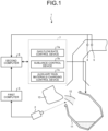
- a converter blowing control system 1 includes: a spectroscopic camera 2 that measures temperature information measured by two-color thermometer of molten iron 12 used as a raw material for blowing in a converter 11 during a period when the molten iron 12 is charged into the converter 11 from a charging ladle 13; a first computer 3 that receives the temperature information measured by two-color thermometer from the spectroscopic camera 2 and calculates a charged molten iron temperature; an exhaust gas flowmeter 4 that measures the flow rate of exhaust gas from the converter 11; an exhaust gas analyzer 5 that analyzes the composition of the exhaust gas from the converter 11; a second computer 6 that calculates an amount of oxygen to be supplied and an amount of a cooling material and so on to be charged for controlling the component and temperature of molten steel at the end of blowing using the charged molten iron temperature calculated by the first computer 3, the flow rate of exhaust gas measured by the exhaust gas flowmeter 4, and the composition of the exhaust gas analyzed by the
- control device 7 includes a gas flow rate control device 7a that controls the flow rate of gas such as oxygen to be supplied to the converter 11, a sublance control device 7b that controls the operation of measuring the temperature and component concentration of the molten metal using the sublance, and an auxiliary raw materials charging control device 7c that controls the operation of charging an auxiliary raw material into the converter 11.
- the second computer 6 may sequentially calculate the temperature of the molten metal during blowing using the charged molten iron temperature calculated by the first computer 3, the flow rate of exhaust gas measured by the exhaust gas flowmeter 4, and the composition of exhaust gas analyzed by the exhaust gas analyzer 5, and the control device 7 may control blowing in the converter 11 based on the temperature of the molten metal during blowing calculated by the second computer 6.
- the spectroscopic camera 2 is a general term for cameras capable of capturing spectroscopic data in addition to a planar image of a measured temperature such as a so-called thermoviewer.
- the spectroscopic data is data collected by dividing a large number of wavelengths contained in emitted light for each wavelength.
- a large number of wavelength data may be collected by the spectroscopic camera 2, and data of arbitrary two wavelengths may be extracted, by a computer or the like, from the obtained data, or, alternatively, if the camera has a bandpass filter in the spectroscopic camera 2, arbitrary two wavelengths may be extracted by the bandpass filter.
- spectroscopic camera capturing is performed by a CCD element; however, a plurality of CCD elements may be mounted, and the individual CCD elements may measure wavelength ranges different from one another.
- the spectroscopic camera 2 it is more preferable to adopt a type (line measurement) having a linear region as a measurement point, rather than a type (spot measurement) having a dotted region as a measurement point. Since the exposed position always moves in the injection flow at the time of molten iron charging, accurate measurement cannot be performed in the spot measurement type in some cases.
- the line measurement type spectrum measurement of the injection flow is performed at a plurality of positions, which enables accurate measurement with high probability. In a case where a spectroscopic camera of the line measurement type is used, a representative value can be obtained by taking the average of the measured values in the measurement region.
- the spectroscopic camera 2 is installed, for example, in front of the furnace on the converter charging side, at a place where an injection flow when the molten iron 12 flows into the converter 11 from the charging ladle 13 can be observed. It is preferable to install the spectroscopic camera 2 at an angle at which the injection flow is looked up because the spectroscopic camera 2 is hardly affected by dust when the molten iron is charged. In a case where the spectroscopic camera 2 is installed above the injection flow at the time of molten iron charging, the amount of soot and smoke between the spectroscopic camera and the injection flow increases because the soot and smoke rises, leading to increase in measurement error.
- an operating floor on which an operation room is provided is located below the position of the injection flow at the time of molten iron charging and thus the spectroscopic camera 2 is preferably installed on the operating floor. Further, it is more preferable that the installation location of the spectroscopic camera 2 is a point which is located below the injection flow at the time of molten iron charging and is moved by 5 to 15 ° in the horizontal direction from a line connecting the centers of the converter and the charging ladle in the horizontal direction with a position where the furnace throat of the converter and an opening of the charging ladle are aligned at the time of molten iron charging as a starting point.
- angles of the converter and the charging ladle while the molten iron is charged change with the progress of the molten iron charging and thus the field of view in which the injection flow can be observed also changes.
- the injection flow relatively largely moves up, down, left, and right in the field of view of the spectroscopic camera 2 as the molten iron charging proceeds.
- the spectroscopic camera 2 is disposed at a position relatively close to the converter on the line connecting the centers of the converter and the charging ladle in the horizontal direction, the injection flow does not move much in the field of view of the spectroscopic camera 2.
- the installation location of the spectroscopic camera 2 is a point which is located below the injection flow at the time of molten iron charging and is moved by 5 to 15 ° in the horizontal direction from the line connecting the centers of the converter and the charging ladle in the horizontal direction.
- the spectroscopic camera 2 is preferably separated from the converter by about 20 m or more. This is because if the distance from the converter is shorter than 20 m, then high-temperature molten material scattered from the converter during charging or blowing may come into contact with the spectroscopic camera 2, which may damage the spectroscopic camera 2.
- temperature information measured by two-color thermometer is collected at a preset sampling rate (for example, every second) from the start to the end of molten iron charging.
- the temperature information measured by two-color thermometer collected by the spectroscopic camera 2 is transmitted to the first computer 3 installed in an operation room or the like, and the first computer 3 calculates the charged molten iron temperature.
- a blowing calculation such as a static control calculation is performed using the calculated charged molten iron temperature.
- the first computer 3 calculating the charged molten iron temperature and the second computer 6 performing the blowing calculation may be the same computer or different computers.
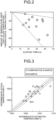
- FIG. 2 is a diagram illustrating an example of a relationship between an elapsed time from measurement of a temperature of molten iron filled in a charging ladle using a thermocouple to measurement, using a two-color thermometer, of a temperature of molten iron for the case of flowing into a converter from the charging ladle and a difference (temperature difference) between the temperature of molten iron measured by the two-color thermometer and the temperature of molten iron measured by the thermocouple.
- a difference temperature difference
- FIG. 3 is a diagram illustrating a relationship between a temperature (intermediate estimated temperature) of the molten metal during blowing estimated from the operation conditions and the exhaust gas information and a temperature (intermediate actual temperature) of the molten metal measured by the sublance charged during blowing in an example and a comparative example in the case of blowing 300 to 350 tons of molten iron using a 350-ton converter.
- the example shows an intermediate estimated temperature in a case where the temperature of the molten iron during charging is reflected in the heat balance calculation as the charged molten iron temperature
- the comparative example shows an intermediate estimated temperature calculated using the charged molten iron temperature estimated from the temperature at the end of the preceding process (dephosphorization treatment in the converter) and an estimated amount of temperature drop.
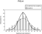
- Table 1 shown below indicates an error of an actual molten steel temperature with respect to a target molten steel temperature at the end of blowing in an example and a comparative example in the case of blowing 300 to 350 tons of molten iron using a 350-ton converter.
- the example is a case where the temperature of the molten iron measured while the molten iron is charged is reflected in the heat balance calculation as the charged molten iron temperature
- the comparative example is a case where the charged molten iron temperature estimated from the temperature at the end of the preceding process and the estimated amount of temperature drop is used.
- an intermediate sublance temperature can be controlled in a narrow range by reflecting the molten iron temperature measured while the molten iron is charged in the heat balance calculation, leading to improvement in accuracy of the molten steel temperature at the time of blowing stop. That is, it was confirmed that the molten steel temperature at the end of blowing can be accurately controlled by reflecting the temperature of the molten iron measured while the molten iron is charged as the charged molten iron temperature in the heat balance calculation.
- the converter blowing control method and the converter blowing control system capable of accurately controlling the temperature of molten steel at the end of blowing to a target value.
Landscapes
- Engineering & Computer Science (AREA)
- Chemical & Material Sciences (AREA)
- Materials Engineering (AREA)
- Metallurgy (AREA)
- Organic Chemistry (AREA)
- Manufacturing & Machinery (AREA)
- Mechanical Engineering (AREA)
- General Engineering & Computer Science (AREA)
- Carbon Steel Or Casting Steel Manufacturing (AREA)
- Radiation Pyrometers (AREA)
- Emergency Protection Circuit Devices (AREA)
Applications Claiming Priority (2)
| Application Number | Priority Date | Filing Date | Title |
|---|---|---|---|
| JP2020113970 | 2020-07-01 | ||
| PCT/JP2021/017239 WO2022004119A1 (fr) | 2020-07-01 | 2021-04-30 | Procédé et système de commande de soufflage de convertisseur |
Publications (2)
| Publication Number | Publication Date |
|---|---|
| EP4177360A1 true EP4177360A1 (fr) | 2023-05-10 |
| EP4177360A4 EP4177360A4 (fr) | 2024-01-17 |
Family
ID=79315181
Family Applications (1)
| Application Number | Title | Priority Date | Filing Date |
|---|---|---|---|
| EP21832549.6A Pending EP4177360A4 (fr) | 2020-07-01 | 2021-04-30 | Procédé et système de commande de soufflage de convertisseur |
Country Status (7)
| Country | Link |
|---|---|
| US (1) | US20230243005A1 (fr) |
| EP (1) | EP4177360A4 (fr) |
| JP (1) | JP7156551B2 (fr) |
| KR (1) | KR102751419B1 (fr) |
| CN (1) | CN115715331A (fr) |
| TW (1) | TWI789807B (fr) |
| WO (1) | WO2022004119A1 (fr) |
Family Cites Families (18)
| Publication number | Priority date | Publication date | Assignee | Title |
|---|---|---|---|---|
| US3955968A (en) * | 1971-06-15 | 1976-05-11 | Koppers Company, Inc. | Method for determining the temperature of a molten metal bath |
| US3920447A (en) * | 1972-02-28 | 1975-11-18 | Pennsylvania Engineering Corp | Steel production method |
| US4417719A (en) * | 1982-08-10 | 1983-11-29 | Kawasaki Steel Corporation | Top-and-bottom blown converter |
| JPH0675037B2 (ja) * | 1987-11-09 | 1994-09-21 | 新日本製鐵株式会社 | 溶鉄成分の検出方法およびそれに基づく精錬方法 |
| JPH0726140B2 (ja) * | 1989-06-07 | 1995-03-22 | 新日本製鐵株式会社 | 転炉製鋼法 |
| US5275488A (en) * | 1993-05-27 | 1994-01-04 | Bethlehem Steel Corporation | BOF drop-in thermocouple |
| JP2803542B2 (ja) * | 1993-12-20 | 1998-09-24 | 日本鋼管株式会社 | 転炉の操業方法 |
| JP3659070B2 (ja) * | 1999-06-25 | 2005-06-15 | 住友金属工業株式会社 | 転炉吹錬時の溶鋼温度および炭素濃度の推定法、および転炉吹錬法 |
| JP5482615B2 (ja) | 2010-10-18 | 2014-05-07 | 新日鐵住金株式会社 | 転炉における吹錬制御方法 |
| JP5527180B2 (ja) | 2010-11-29 | 2014-06-18 | 新日鐵住金株式会社 | 転炉吹錬方法及び転炉吹錬システム |
| JP6075037B2 (ja) * | 2012-11-30 | 2017-02-08 | 株式会社リコー | 着脱ユニット、及び、画像形成装置 |
| CN103451353A (zh) * | 2013-08-30 | 2013-12-18 | 武汉钢铁(集团)公司 | 基于模拟副枪静态检测的启动转炉动态控制模型的方法 |
| CN105925750A (zh) * | 2016-05-13 | 2016-09-07 | 南阳理工学院 | 一种基于神经网络的炼钢终点预测方法 |
| CN106979832B (zh) * | 2017-03-22 | 2023-08-15 | 河南北方红阳机电有限公司 | 一种光纤分光测温系统及其测温方法 |
| JP6617855B2 (ja) * | 2017-06-30 | 2019-12-11 | Jfeスチール株式会社 | 転炉の操業監視方法および転炉の操業方法 |
| JP6687080B2 (ja) * | 2017-10-16 | 2020-04-22 | Jfeスチール株式会社 | 溶湯温度補正装置、溶湯温度補正方法、及び溶湯の製造方法 |
| CN110551867A (zh) * | 2018-06-01 | 2019-12-10 | 上海梅山钢铁股份有限公司 | 一种基于炉渣成分预测的转炉冶炼控制方法 |
| CN109517937A (zh) * | 2019-01-10 | 2019-03-26 | 山东莱钢永锋钢铁有限公司 | 一种转炉冶炼热平衡方法 |
-
2021
- 2021-04-30 US US18/011,747 patent/US20230243005A1/en active Pending
- 2021-04-30 JP JP2021557858A patent/JP7156551B2/ja active Active
- 2021-04-30 EP EP21832549.6A patent/EP4177360A4/fr active Pending
- 2021-04-30 WO PCT/JP2021/017239 patent/WO2022004119A1/fr not_active Ceased
- 2021-04-30 CN CN202180045527.4A patent/CN115715331A/zh active Pending
- 2021-04-30 KR KR1020227044493A patent/KR102751419B1/ko active Active
- 2021-06-30 TW TW110124088A patent/TWI789807B/zh active
Also Published As
| Publication number | Publication date |
|---|---|
| US20230243005A1 (en) | 2023-08-03 |
| BR112022026402A2 (pt) | 2023-01-17 |
| KR20230013096A (ko) | 2023-01-26 |
| JPWO2022004119A1 (fr) | 2022-01-06 |
| WO2022004119A1 (fr) | 2022-01-06 |
| EP4177360A4 (fr) | 2024-01-17 |
| CN115715331A (zh) | 2023-02-24 |
| JP7156551B2 (ja) | 2022-10-19 |
| TW202206608A (zh) | 2022-02-16 |
| KR102751419B1 (ko) | 2025-01-07 |
| TWI789807B (zh) | 2023-01-11 |
Similar Documents
| Publication | Publication Date | Title |
|---|---|---|
| JP7088439B1 (ja) | 転炉の操業方法及び転炉の吹錬制御システム | |
| KR101362712B1 (ko) | 배기가스 신호를 이용한 전로 공정의 제어 방법 | |
| KR100321670B1 (ko) | Bof용기내강철의탄소함량측정방법,광측정기및측정장치 | |
| EP4177361A1 (fr) | Procédé de commande de soufflage de convertisseur et système de commande de soufflage de convertisseur | |
| EP4177360A1 (fr) | Procédé et système de commande de soufflage de convertisseur | |
| RU2813298C1 (ru) | Способ управления продувкой конвертера и система управления продувкой конвертера | |
| CN114838830A (zh) | 一种授铁工艺段温度检测方法、装置及系统 | |
| RU2811549C1 (ru) | Способ управления продувкой конвертера и система управления продувкой конвертера | |
| BR112022026402B1 (pt) | Método de controle de sopro de conversor e sistema de controle de sopro de conversor | |
| JP2022029570A (ja) | 減圧下における溶鋼温度の測定方法 | |
| BR112022026573B1 (pt) | Método de controle de sopro de conversor e sistema de controle de sopro de conversor | |
| KR100994047B1 (ko) | 노내 침수시 노열 보상방법 | |
| KR100383277B1 (ko) | 고로 내의 가스류 변동측정방법 | |
| US20260043613A1 (en) | Slag discharge amount estimation method | |
| TW201734214A (zh) | 熔融生鐵預備處理方法及熔融生鐵預備處理控制裝置 | |
| JPS5856002B2 (ja) | 酸素転炉の終点制御法 | |
| CN108342538A (zh) | 一种提高tso转炉副枪探头的精确测量碳含量的方法 | |
| Ren et al. | Experimental Research of Continuous Temperature Measurement for Molten Metal Bath through Bottom‐Blowing Component | |
| JPS6139374B2 (fr) |
Legal Events
| Date | Code | Title | Description |
|---|---|---|---|
| STAA | Information on the status of an ep patent application or granted ep patent |
Free format text: STATUS: THE INTERNATIONAL PUBLICATION HAS BEEN MADE |
|
| PUAI | Public reference made under article 153(3) epc to a published international application that has entered the european phase |
Free format text: ORIGINAL CODE: 0009012 |
|
| STAA | Information on the status of an ep patent application or granted ep patent |
Free format text: STATUS: REQUEST FOR EXAMINATION WAS MADE |
|
| 17P | Request for examination filed |
Effective date: 20221219 |
|
| AK | Designated contracting states |
Kind code of ref document: A1 Designated state(s): AL AT BE BG CH CY CZ DE DK EE ES FI FR GB GR HR HU IE IS IT LI LT LU LV MC MK MT NL NO PL PT RO RS SE SI SK SM TR |
|
| DAV | Request for validation of the european patent (deleted) | ||
| DAX | Request for extension of the european patent (deleted) | ||
| A4 | Supplementary search report drawn up and despatched |
Effective date: 20231215 |
|
| RIC1 | Information provided on ipc code assigned before grant |
Ipc: F27D 21/02 20060101ALI20231211BHEP Ipc: F27D 19/00 20060101ALI20231211BHEP Ipc: F27B 1/28 20060101ALI20231211BHEP Ipc: C21C 5/46 20060101ALI20231211BHEP Ipc: C21C 5/30 20060101AFI20231211BHEP |
|
| STAA | Information on the status of an ep patent application or granted ep patent |
Free format text: STATUS: EXAMINATION IS IN PROGRESS |
|
| 17Q | First examination report despatched |
Effective date: 20241205 |