EP4177380A2 - Membran-elektrodenanordnung, wasserstofferzeugungsvorrichtung, verfahren zur herstellung einer katalysatortinte und verfahren zur herstellung einer membran-elektrodenanordnung - Google Patents
Membran-elektrodenanordnung, wasserstofferzeugungsvorrichtung, verfahren zur herstellung einer katalysatortinte und verfahren zur herstellung einer membran-elektrodenanordnung Download PDFInfo
- Publication number
- EP4177380A2 EP4177380A2 EP22179361.5A EP22179361A EP4177380A2 EP 4177380 A2 EP4177380 A2 EP 4177380A2 EP 22179361 A EP22179361 A EP 22179361A EP 4177380 A2 EP4177380 A2 EP 4177380A2
- Authority
- EP
- European Patent Office
- Prior art keywords
- water
- catalyst layer
- anode
- particle
- electrode assembly
- Prior art date
- Legal status (The legal status is an assumption and is not a legal conclusion. Google has not performed a legal analysis and makes no representation as to the accuracy of the status listed.)
- Granted
Links
Images


Classifications
-
- C—CHEMISTRY; METALLURGY
- C25—ELECTROLYTIC OR ELECTROPHORETIC PROCESSES; APPARATUS THEREFOR
- C25B—ELECTROLYTIC OR ELECTROPHORETIC PROCESSES FOR THE PRODUCTION OF COMPOUNDS OR NON-METALS; APPARATUS THEREFOR
- C25B11/00—Electrodes; Manufacture thereof not otherwise provided for
- C25B11/04—Electrodes; Manufacture thereof not otherwise provided for characterised by the material
- C25B11/051—Electrodes formed of electrocatalysts on a substrate or carrier
- C25B11/052—Electrodes comprising one or more electrocatalytic coatings on a substrate
-
- C—CHEMISTRY; METALLURGY
- C25—ELECTROLYTIC OR ELECTROPHORETIC PROCESSES; APPARATUS THEREFOR
- C25B—ELECTROLYTIC OR ELECTROPHORETIC PROCESSES FOR THE PRODUCTION OF COMPOUNDS OR NON-METALS; APPARATUS THEREFOR
- C25B1/00—Electrolytic production of inorganic compounds or non-metals
- C25B1/01—Products
- C25B1/02—Hydrogen or oxygen
- C25B1/04—Hydrogen or oxygen by electrolysis of water
-
- C—CHEMISTRY; METALLURGY
- C25—ELECTROLYTIC OR ELECTROPHORETIC PROCESSES; APPARATUS THEREFOR
- C25B—ELECTROLYTIC OR ELECTROPHORETIC PROCESSES FOR THE PRODUCTION OF COMPOUNDS OR NON-METALS; APPARATUS THEREFOR
- C25B9/00—Cells or assemblies of cells; Constructional parts of cells; Assemblies of constructional parts, e.g. electrode-diaphragm assemblies; Process-related cell features
- C25B9/17—Cells comprising dimensionally-stable non-movable electrodes; Assemblies of constructional parts thereof
- C25B9/19—Cells comprising dimensionally-stable non-movable electrodes; Assemblies of constructional parts thereof with diaphragms
- C25B9/23—Cells comprising dimensionally-stable non-movable electrodes; Assemblies of constructional parts thereof with diaphragms comprising ion-exchange membranes in or on which electrode material is embedded
-
- C—CHEMISTRY; METALLURGY
- C25—ELECTROLYTIC OR ELECTROPHORETIC PROCESSES; APPARATUS THEREFOR
- C25B—ELECTROLYTIC OR ELECTROPHORETIC PROCESSES FOR THE PRODUCTION OF COMPOUNDS OR NON-METALS; APPARATUS THEREFOR
- C25B11/00—Electrodes; Manufacture thereof not otherwise provided for
- C25B11/04—Electrodes; Manufacture thereof not otherwise provided for characterised by the material
- C25B11/051—Electrodes formed of electrocatalysts on a substrate or carrier
- C25B11/073—Electrodes formed of electrocatalysts on a substrate or carrier characterised by the electrocatalyst material
- C25B11/075—Electrodes formed of electrocatalysts on a substrate or carrier characterised by the electrocatalyst material consisting of a single catalytic element or catalytic compound
- C25B11/081—Electrodes formed of electrocatalysts on a substrate or carrier characterised by the electrocatalyst material consisting of a single catalytic element or catalytic compound the element being a noble metal
-
- C—CHEMISTRY; METALLURGY
- C25—ELECTROLYTIC OR ELECTROPHORETIC PROCESSES; APPARATUS THEREFOR
- C25B—ELECTROLYTIC OR ELECTROPHORETIC PROCESSES FOR THE PRODUCTION OF COMPOUNDS OR NON-METALS; APPARATUS THEREFOR
- C25B11/00—Electrodes; Manufacture thereof not otherwise provided for
- C25B11/04—Electrodes; Manufacture thereof not otherwise provided for characterised by the material
- C25B11/051—Electrodes formed of electrocatalysts on a substrate or carrier
- C25B11/073—Electrodes formed of electrocatalysts on a substrate or carrier characterised by the electrocatalyst material
- C25B11/091—Electrodes formed of electrocatalysts on a substrate or carrier characterised by the electrocatalyst material consisting of at least one catalytic element and at least one catalytic compound; consisting of two or more catalytic elements or catalytic compounds
- C25B11/093—Electrodes formed of electrocatalysts on a substrate or carrier characterised by the electrocatalyst material consisting of at least one catalytic element and at least one catalytic compound; consisting of two or more catalytic elements or catalytic compounds at least one noble metal or noble metal oxide and at least one non-noble metal oxide
-
- C—CHEMISTRY; METALLURGY
- C25—ELECTROLYTIC OR ELECTROPHORETIC PROCESSES; APPARATUS THEREFOR
- C25B—ELECTROLYTIC OR ELECTROPHORETIC PROCESSES FOR THE PRODUCTION OF COMPOUNDS OR NON-METALS; APPARATUS THEREFOR
- C25B11/00—Electrodes; Manufacture thereof not otherwise provided for
- C25B11/04—Electrodes; Manufacture thereof not otherwise provided for characterised by the material
- C25B11/051—Electrodes formed of electrocatalysts on a substrate or carrier
- C25B11/073—Electrodes formed of electrocatalysts on a substrate or carrier characterised by the electrocatalyst material
- C25B11/091—Electrodes formed of electrocatalysts on a substrate or carrier characterised by the electrocatalyst material consisting of at least one catalytic element and at least one catalytic compound; consisting of two or more catalytic elements or catalytic compounds
- C25B11/097—Electrodes formed of electrocatalysts on a substrate or carrier characterised by the electrocatalyst material consisting of at least one catalytic element and at least one catalytic compound; consisting of two or more catalytic elements or catalytic compounds comprising two or more noble metals or noble metal alloys
-
- Y—GENERAL TAGGING OF NEW TECHNOLOGICAL DEVELOPMENTS; GENERAL TAGGING OF CROSS-SECTIONAL TECHNOLOGIES SPANNING OVER SEVERAL SECTIONS OF THE IPC; TECHNICAL SUBJECTS COVERED BY FORMER USPC CROSS-REFERENCE ART COLLECTIONS [XRACs] AND DIGESTS
- Y02—TECHNOLOGIES OR APPLICATIONS FOR MITIGATION OR ADAPTATION AGAINST CLIMATE CHANGE
- Y02E—REDUCTION OF GREENHOUSE GAS [GHG] EMISSIONS, RELATED TO ENERGY GENERATION, TRANSMISSION OR DISTRIBUTION
- Y02E60/00—Enabling technologies; Technologies with a potential or indirect contribution to GHG emissions mitigation
- Y02E60/30—Hydrogen technology
- Y02E60/36—Hydrogen production from non-carbon containing sources, e.g. by water electrolysis
Definitions
- the present invention relates to a membrane electrode assembly, a hydrogen producing device, a method of producing catalyst ink, and a method of producing a membrane electrode assembly.
- water electrolysis According to a technique called water electrolysis conventionally known, hydrogen (H 2 ) is produced through electrolysis of water (H 2 O).
- Several types of water electrolysis are prepared in response to electrolytes to be used.
- One of these types is solid polymer water electrolysis that uses an ion-exchange membrane (electrolyte membrane) as an electrolyte.
- the solid polymer water electrolysis uses a cell with catalyst layers formed on both surfaces of the electrolyte membrane.
- a voltage is applied between an anode-side catalyst layer and a cathode-side catalyst layer and water is supplied to the anode-side catalyst layer. This causes electrochemical reactions as follows at the anode-side catalyst layer and the cathode-side catalyst layer.
- hydrogen is output from the cathode-side catalyst layer.
- Patent Literature 1 The conventional solid polymer water electrolysis is disclosed in Patent Literature 1, for example.
- Patent Literature 1 Japanese Patent Application Laid-Open No. 2019-083085
- oxygen is to be output from the anode-side catalyst layer. This necessitates supply of water and output of oxygen to and from the anode-side catalyst layer. In some cases, during these supply and output, output of oxygen is hindered by the influence of water supplied to the catalyst layer. In such cases, degradation of the performance of outputting oxygen causes a problem that efficiency of hydrogen production through the solid polymer water electrolysis will be reduced.
- water filling the anode-side catalyst layer partially leaks to the cathode-side catalyst layer through the electrolyte membrane. Then, the water having entered the cathode-side catalyst layer may hinder output of generated hydrogen. This causes a problem that efficiency of hydrogen output will be reduced.
- the present invention has been made in view of the above-described circumstances, and is intended to provide a technique that achieves improvement of the performance of outputting a substance generated in a catalyst layer.
- a first aspect of the present invention is intended for a membrane electrode assembly comprising: an electrolyte membrane; and an anode catalyst layer formed on one surface of the electrolyte membrane, wherein the anode catalyst layer includes a catalyst particle; an ionomer; and a water-repellent particle, and the water-repellent particle is a ceramic particle with a fluorine group or a metallic particle with a fluorine group.
- the ratio of the water-repellent particle to the catalyst particle is equal to or greater than 2 wt% and equal to or less than 20 wt%.
- the ratio of the water-repellent particle to the catalyst particle is equal to or greater than 5 wt% and equal to or less than 15 wt%.
- the ionomer in the membrane electrode assembly according to any one of the first to third aspects, has an EW value of equal to or less than 950.
- the ratio of the ionomer to the catalyst particle is equal to or greater than 8 wt% and equal to or less than 45 wt%.
- the membrane electrode assembly in the membrane electrode assembly according to any one of the first to fifth aspects, is used for solid polymer water electrolysis.
- a seventh aspect of the present invention is intended for a hydrogen producing device that produces hydrogen through solid polymer water electrolysis, comprising the membrane electrode assembly according to the sixth aspect.
- An eighth aspect of the present invention is intended for a method of producing catalyst ink to become an anode catalyst layer of a membrane electrode assembly, comprising: a first step of forming a first preparation liquid by blending a catalyst particle and water; a second step of forming a second preparation liquid by adding an alcohol solution to the first preparation liquid; a third step of forming a third preparation liquid by adding a water-repellent particle to the second preparation liquid; and a fourth step of forming a fourth preparation liquid by adding a solution of an ionomer to the third preparation liquid, wherein the water-repellent particle is a ceramic particle with a fluorine group or a metallic particle with a fluorine group.
- the ratio of the alcohol solution to the catalyst ink is equal to or greater than 15 wt%.
- a tenth aspect of the present invention is intended for a method of producing a membrane electrode assembly comprising the step of: applying catalyst ink produced by the producing method according to the eighth or ninth aspect to one surface of an electrolyte membrane and drying the applied catalyst ink, thereby forming the anode catalyst layer.
- adding the water-repellent particle to the anode catalyst layer achieves improvement of the performance of outputting a substance generated in the anode catalyst layer.
- the second aspect of the present invention achieves improvement of the performance of outputting a substance generated in the anode catalyst layer and achieves reduction in the probability of degradation of electrical conductivity in the anode catalyst layer caused by the influence of the fluorine group.
- the third aspect of the present invention achieves further improvement of the performance of outputting a substance generated in the anode catalyst layer and achieves further reduction in the probability of degradation of electrical conductivity in the anode catalyst layer caused by the influence of the fluorine group.
- the number of ion-exchange groups in a polymer chain of the ionomer is increased. This allows oxonium ions to propagate favorably.
- the fifth aspect of the present invention allows the catalyst particle to be covered with the ionomer favorably. Furthermore, the presence of a void left in the anode catalyst layer achieves favorable output of a substance to be generated.
- the sixth aspect of the present invention achieves improvement of the performance of outputting oxygen generated in the anode catalyst layer, making it possible to improve the efficiency of producing hydrogen through solid polymer water electrolysis.
- the water-repellent particle is added to the catalyst ink to become the anode catalyst layer. This achieves improvement of the performance of outputting a substance generated in the anode catalyst layer. Furthermore, the water-repellent particle is added after addition of the alcohol solution. This allows the water-repellent particle to disperse uniformly.
- the ninth aspect of the present invention allows the water-repellent particle to disperse more uniformly.
- Fig. 1 is a schematic view of a hydrogen producing device 1 according to a preferred embodiment of the present invention.
- the hydrogen producing device 1 is a device that produces hydrogen through solid polymer water electrolysis.
- the hydrogen producing device 1 includes a cell composed of an electrolyte membrane 10, an anode catalyst layer 21, an anode gas diffusion layer 22, an anode gasket 23, an anode separator 24, a cathode catalyst layer 31, a cathode gas diffusion layer 32, a cathode gasket 33, and a cathode separator 34.
- the electrolyte membrane 10, the anode catalyst layer 21, and the cathode catalyst layer 31 form a stack corresponding to a membrane electrode assembly (MEA) 50 according to the preferred embodiment of the present invention.
- MEA membrane electrode assembly
- the electrolyte membrane 10 is a membrane like a thin plate having ion conductivity (ion-exchange membrane).
- a fluorine-based or hydrocarbon-based polymer electrolyte membrane is used as the electrolyte membrane 10. More specifically, a polymer electrolyte membrane containing perfluorocarbon sulfonic acid is used as the electrolyte membrane 10, for example.
- the electrolyte membrane 10 has a thickness from 5 to 30 ⁇ m, for example.
- the anode catalyst layer 21 is a layer functioning as an anode-side electrode.
- the anode catalyst layer 21 is formed on an anode-side surface of the electrolyte membrane 10.
- the anode catalyst layer 21 contains a large number of catalyst particles.
- the catalyst particles are particles of iridium oxide (IrOx), platinum (Pt), an alloy of iridium (Ir) and ruthenium (Ru), or an alloy of iridium (Ir) and titanium dioxide (TiO 2 ), for example.
- water (H 2 O) is supplied to the anode catalyst layer 21.
- a voltage is applied between the anode catalyst layer 21 and the cathode catalyst layer 31 from a power supply 40 described later. By doing so, by the actions of the applied voltage and the catalyst particles, the water is electrolyzed into hydrogen ions (H + ), oxygen (O 2 ), and electrons (e - ) in the anode catalyst layer 21.
- composition of the anode catalyst layer 21 will be described later in more detail.
- the anode gas diffusion layer 22 is a layer for supplying water uniformly to the anode catalyst layer 21 and for transmitting oxygen and electrons generated in the anode catalyst layer 21 to the anode separator 24.
- the anode gas diffusion layer 22 is stacked on an outer surface of the anode catalyst layer 21.
- the anode catalyst layer 21 is interposed between the electrolyte membrane 10 and the anode gas diffusion layer 22.
- the anode gas diffusion layer 22 has electrical conductivity and is made of a porous material. As an example, carbon paper is used as the anode gas diffusion layer 22.
- the anode gasket 23 is a layer for preventing leakage of water and oxygen from the anode catalyst layer 21 and from the anode gas diffusion layer 22 to their surroundings. As shown in Fig. 1 , the anode gasket 23 is formed on the anode-side surface of the electrolyte membrane 10 and surrounds the anode catalyst layer 21 and the anode gas diffusion layer 22.
- the anode separator 24 is a layer for supplying water to the anode gas diffusion layer 22 and for transmitting electrons coming from the anode catalyst layer 21 through the anode gas diffusion layer 22 to the power supply 40.
- the anode separator 24 also functions to output oxygen generated in the anode catalyst layer 21 to the outside.
- the anode separator 24 is formed on an outer surface of the anode gas diffusion layer 22 and on an outer surface of the anode gasket 23.
- the anode catalyst layer 21, the anode gas diffusion layer 22, and the anode gasket 23 are interposed between the electrolyte membrane 10 and the anode separator 24.
- the anode separator 24 has electrical conductivity and is made of a material without permeability to gas.
- the anode separator 24 is provided with a large number of grooves 241. Water is supplied to the anode gas diffusion layer 22 through the grooves 241 of the anode separator 24. Oxygen generated in the anode catalyst layer 21 passes through the anode gas diffusion layer 22 and is then output to the outside through the grooves 241 of the anode separator 24.
- the cathode catalyst layer 31 is a layer functioning as a cathode-side electrode.
- the cathode catalyst layer 31 is formed on a cathode-side surface of the electrolyte membrane 10 (a surface on the opposite side to the anode catalyst layer 21).
- the cathode catalyst layer 31 contains a large number of carbon particles on which catalyst particles are supported.
- the catalyst particles are particles of platinum, for example.
- the catalyst particles may be prepared by mixing a tiny amount of ruthenium or cobalt particles into particles of platinum.
- hydrogen ions (H + ) and electrons (e - ) are supplied to the cathode catalyst layer 31.
- a voltage is applied between the anode catalyst layer 21 and the cathode catalyst layer 31 by the power supply 40 described later.
- a reduction reaction is caused in the cathode catalyst layer 31 to generate hydrogen gas (H 2 ) from the hydrogen ions and the electrons.
- the cathode gas diffusion layer 32 is a layer for transmitting electrons from the cathode separator 34 to the cathode catalyst layer 31 and for transmitting hydrogen generated in the cathode catalyst layer 31 to the cathode separator 34.
- the cathode gas diffusion layer 32 is stacked on an outer surface of the cathode catalyst layer 31.
- the cathode catalyst layer 31 is interposed between the electrolyte membrane 10 and the cathode gas diffusion layer 32.
- the cathode gas diffusion layer 32 has electrical conductivity and is made of a porous material. As an example, carbon paper is used as the cathode gas diffusion layer 32.
- the cathode gasket 33 is a layer for preventing leakage of hydrogen from the cathode catalyst layer 31 and from the cathode gas diffusion layer 32 to their surroundings. As shown in Fig. 1 , the cathode gasket 33 is formed on the cathode-side surface of the electrolyte membrane 10 and surrounds the cathode catalyst layer 31 and the cathode gas diffusion layer 32.
- the cathode separator 34 is a layer for transmitting electrons supplied from the power supply 40 to the cathode gas diffusion layer 32 and for outputting generated hydrogen to the outside.
- the cathode separator 34 is formed on an outer surface of the cathode gas diffusion layer 32 and on an outer surface of the cathode gasket 33.
- the cathode catalyst layer 31, the cathode gas diffusion layer 32, and the cathode gasket 33 are interposed between the electrolyte membrane 10 and the cathode separator 34.
- the cathode separator 34 has electrical conductivity and is made of a material without permeability to gas.
- the cathode separator 34 is provided with a large number of grooves 341. Hydrogen from the cathode gas diffusion layer 32 passes through the grooves 341 and is then output to the outside.
- the power supply 40 is connected between the anode separator 24 and the cathode separator 34. More specifically, the power supply 40 has a positive terminal electrically connected to the anode separator 24. The power supply 40 has a negative terminal electrically connected to the cathode separator 34. The power supply 40 applies a voltage necessary for electrolysis of water between the anode separator 24 and the cathode separator 34.
- water is supplied from the anode separator 24 to the anode catalyst layer 21 through the anode gas diffusion layer 22. Then, by the actions of a voltage applied from the power supply 40 and the catalyst parties in the anode catalyst layer 21, water is decomposed into hydrogen ions, oxygen, and electrons.
- the hydrogen ions propagate through the electrolyte membrane 10 into the cathode catalyst layer 31.
- the oxygen passes through the anode gas diffusion layer 22 and the anode separator 24 and is then output to the outside.
- the electrons pass through the anode gas diffusion layer 22, the anode separator 24, the power supply 40, the cathode separator 34, and the cathode gas diffusion layer 32 and then flow into the cathode catalyst layer 31.
- the hydrogen ions and the electrons are combined with each other to generate hydrogen.
- the generated hydrogen passes through the cathode gas diffusion layer 32 and the cathode separator 34 and is then output to the outside. In this way, hydrogen is produced.
- Fig. 2 is a schematic view conceptually showing the composition of the anode catalyst layer 21.
- the anode catalyst layer 21 includes multiple catalyst particles 51, an ionomer 52, and multiple water-repellent particles 53.
- the catalyst particles 51 are particles for causing electrolysis of water.
- the catalyst particles 51 are made of iridium oxide, platinum, an alloy of iridium and ruthenium, or an alloy of iridium and titanium dioxide.
- the ionomer 52 is an electrolyte polymer covering the catalyst particles 51.
- the ionomer 52 functions to transport hydrogen ions generated through electrolysis of water in the anode catalyst layer 21.
- nafion perfluorocarbon sulfonic acid
- the ionomer 52 has a polymer chain with an ion-exchange group such as a sulfone group.
- the hydrogen ions are combined with water in the cathode catalyst layer 31 to become oxonium ions (H 3 O + ). These oxonium ions propagate through the ion-exchange group of the ionomer 52.
- an EW value indicating the dry mass of the ionomer 52 per mol of ion-exchange groups (the reciprocal of the number of ion-exchange groups per unit mass of the ionomer 52) will be set equal to or less than 950.
- the EW value is desirably set equal to or greater than 650 and equal to or less than 950.
- the ratio of the ionomer 52 to the catalyst particles 51 is too small, it becomes impossible to cover the catalyst particles 51 with the ionomer 52 sufficiently. This makes it difficult for oxonium ions to propagate through the ionomer 52 favorably.
- the ratio of the ionomer 52 to the catalyst particles 51 is too large, voids in the cathode catalyst layer 31 are reduced. This becomes hindrance to diffusion of water in the anode catalyst layer 21 or to output of oxygen generated in the anode catalyst layer 21.
- the ratio of the ionomer 52 to the catalyst particles 51 is desirably set to a ratio that allows the catalyst particles 51 to be covered with the ionomer 52 favorably, and achieves favorable diffusion of water and favorable output of oxygen. More specifically, the ratio (ratio by weight) of the ionomer 52 to the catalyst particles 51 is desirably set equal to or greater than 8 wt% and equal to or less than 45 wt%. More desirably, the ratio of the ionomer 52 (ratio by weight) to the catalyst particles 51 is set equal to or greater than 10 wt% and equal to or less than 25 wt%.
- the water-repellent particles 53 are additives for improving the performance of outputting oxygen generated in the anode catalyst layer 21.
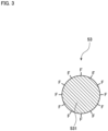
- Fig. 3 is a conceptual view of the water-repellent particle 53.
- the water-repellent particle 53 is composed of a body particle 531, and multiple fluorine groups (F) with water repellency provided on a surface of the body particle 531.
- the body particle 531 is a ceramic particle or a metallic particle, for example.
- the ceramic particle is a particle of titanium oxide (TiO 2 ), for example.
- the metallic particle is a particle of a noble metal such as platinum (Pt), silver (Ag), or gold (Au), for example.
- the water-repellent particle 53 has a diameter of equal to or greater than 2 nm and equal to or less than 500 nm, for example.
- the anode catalyst layer 21 contains water and receives a high voltage of about 2 V.
- oxidation of carbon (electron emission) proceeds in parallel with electrolysis.
- a chemical reaction expressed by the following formula occurs to unintentionally cause disappearance of carbon (C).
- C it is desirable to avoid use of carbon and to use a ceramic particle or a metallic particle as the body particle 531 as described above.
- Fig. 4 is a graph showing a relationship between the quantity of the water-repellent particles 53 added to the anode catalyst layer 21 and voltage characteristics of the hydrogen producing device 1.
- a horizontal axis shows the ratio (ratio by weight) of the water-repellent particles 53 to the catalyst particles 51.
- a vertical axis shows a voltage value to be applied from the power supply 40 for generating hydrogen of a predetermined amount. The voltage value shown in the graph of Fig. 4 is determined at a current density of 2.0 A/cm 2 .
- water in the anode catalyst layer 21 is repelled by the water-repelling action of the fluorine groups. This reduces a likelihood that movement of oxygen generated in the anode catalyst layer 21 will be hindered by water. Thus, it becomes possible to output oxygen efficiently from the anode catalyst layer 21. Improving the performance of outputting oxygen facilitates electrolysis of water further in the anode catalyst layer 21.
- adding the water-repellent particles 53 to the anode catalyst layer 21 reduces a likelihood that water in the anode catalyst layer 21 will enter the cathode catalyst layer 31 through the electrolyte membrane 10.
- movement of hydrogen generated in the cathode catalyst layer 31 becomes less prone to hindrance by water.
- adding the water-repellent particles 53 to the anode catalyst layer 21 makes it possible to reduce a voltage value to be applied from the power supply 40 compared to a case in the absence of addition of the water-repellent particles 53. Specifically, this achieves improvement of the efficiency of producing hydrogen through solid polymer water electrolysis.
- the water-repellent particles 53 will be added to a quantity with which the performance of outputting oxygen generated in the anode catalyst layer 21 can be improved and the probability of degradation of electrical conductivity in the anode catalyst layer 21 caused by the influence of the fluorine groups can be reduced.
- the ratio (ratio by weight) of the water-repellent particles 53 to the catalyst particles 51 is desirably set equal to or greater than 2 wt% and equal to or less than 20 wt%. More desirably, the ratio (ratio by weight) of the water-repellent particles 53 to the catalyst particles 51 is set equal to or greater than 5 wt% and equal to or less than 15 wt%.
- the ratio (ratio by weight) of the water-repellent particles 53 to the catalyst particles 51 is preferably set to 10 wt%.
- reducing the above-described EW value of the ionomer 52 contributes to increasing a moisture content in the anode catalyst layer 21.
- adding the water-repellent particles 53 contributes to reducing a moisture content in the anode catalyst layer 21.
- the anode catalyst layer 21 is formed by applying catalyst ink in paste form on a surface of the electrolyte membrane 10. The following describes a method of producing the catalyst ink to become the anode catalyst layer 21.
- Fig. 5 is a flowchart showing a procedure of producing the catalyst ink.
- the catalyst particles 51 and water are first blended to form a first preparation liquid (first step S1).
- the water is added to prevent the catalyst particles 51 from catching fire.
- an alcohol solution is added to the first preparation liquid to form a second preparation liquid (second step S2).
- the alcohol solution is methanol, ethanol, 1-propanol, or 2-propanol, for example.
- the water-repellent particles 53 are added to the second preparation liquid to form a third preparation liquid (third step S3).
- the water-repellent particles 53 are ceramic particles with fluorine groups or metallic particles with fluorine groups.
- the water-repellent particles 53 disperse in the alcohol solution added in the second step S2.
- the alcohol solution having a small angle of contact (having high compatibility with the water-repellent particles 53) is added in advance in the second step S2, and then the water-repellent particles 53 are added in the third step S3. This allows the water-repellent particles 53 to disperse uniformly in the third preparation liquid.
- an ionomer solution is added to the third preparation liquid to form a fourth preparation liquid (fourth step S4).
- the ionomer solution is a solution prepared by dissolving the ionomer 52 in water and alcohol.
- the ionomer solution has a high proportion of water, so that it is added after the water-repellent particles 53 are added and disperse in the third step S3.
- the fourth preparation liquid is agitated, for example. This causes the water-repellent particles 53 to disperse more uniformly in the fourth preparation liquid. As a result, the catalyst ink is generated.
- the ratio (ratio by weight) of the alcohol solution to the catalyst ink finally generated is desirably set equal to or greater than 15 wt%. This allows the water-repellent particles 53 to disperse with still higher performance in the catalyst ink.
- Fig. 6 is a flowchart showing a procedure of producing the membrane electrode assembly 50.
- the catalyst ink for anode produced by the above-described procedure is applied to one of the surfaces of the electrolyte membrane 10 (sixth step S6). Then, the applied catalyst ink is dried (seventh step S7). By doing so, the anode catalyst layer 21 is formed on the one surface of the electrolyte membrane 10.
- catalyst ink for cathode is applied to the other surface of the electrolyte membrane 10 (eighth step S8). Then, the applied catalyst ink is dried (ninth step S9). By doing so, the cathode catalyst layer 31 is formed on the other surface of the electrolyte membrane 10. As a result, the membrane electrode assembly 50 composed of the electrolyte membrane 10, the anode catalyst layer 21, and the cathode catalyst layer 31 is obtained.
- Order of implementation may be reversed between formation of the anode catalyst layer 21 including the sixth step S6 and the seventh step S7 and formation of the cathode catalyst layer 31 including the eighth step S8 and the ninth step S9.
Landscapes
- Chemical & Material Sciences (AREA)
- Engineering & Computer Science (AREA)
- Chemical Kinetics & Catalysis (AREA)
- Electrochemistry (AREA)
- Materials Engineering (AREA)
- Metallurgy (AREA)
- Organic Chemistry (AREA)
- Inorganic Chemistry (AREA)
- Electrolytic Production Of Non-Metals, Compounds, Apparatuses Therefor (AREA)
- Electrodes For Compound Or Non-Metal Manufacture (AREA)
Applications Claiming Priority (1)
| Application Number | Priority Date | Filing Date | Title |
|---|---|---|---|
| JP2021148400A JP7345527B2 (ja) | 2021-09-13 | 2021-09-13 | 膜電極接合体、水素製造装置、触媒インクの製造方法、および膜電極接合体の製造方法 |
Publications (3)
| Publication Number | Publication Date |
|---|---|
| EP4177380A2 true EP4177380A2 (de) | 2023-05-10 |
| EP4177380A3 EP4177380A3 (de) | 2023-06-07 |
| EP4177380B1 EP4177380B1 (de) | 2025-08-06 |
Family
ID=82117672
Family Applications (1)
| Application Number | Title | Priority Date | Filing Date |
|---|---|---|---|
| EP22179361.5A Active EP4177380B1 (de) | 2021-09-13 | 2022-06-16 | Membran-elektrodenanordnung, wasserstofferzeugungsvorrichtung, verfahren zur herstellung einer katalysatortinte und verfahren zur herstellung einer membran-elektrodenanordnung |
Country Status (4)
| Country | Link |
|---|---|
| EP (1) | EP4177380B1 (de) |
| JP (1) | JP7345527B2 (de) |
| KR (1) | KR102636973B1 (de) |
| CN (1) | CN115786929B (de) |
Cited By (1)
| Publication number | Priority date | Publication date | Assignee | Title |
|---|---|---|---|---|
| CN115786929A (zh) * | 2021-09-13 | 2023-03-14 | 株式会社斯库林集团 | 膜电极接合体及制造方法、氢制造装置、油墨的制造方法 |
Families Citing this family (3)
| Publication number | Priority date | Publication date | Assignee | Title |
|---|---|---|---|---|
| WO2024242182A1 (ja) | 2023-05-24 | 2024-11-28 | 国立大学法人山形大学 | 固体高分子形燃料電池用電解質膜、膜電極接合体、固体高分子形燃料電池、および、それらの製造方法、並びに、固体高分子形水電解用電解質膜 |
| WO2025183215A1 (ja) * | 2024-02-28 | 2025-09-04 | 東京瓦斯株式会社 | 触媒層付き電解質膜、水電解セル及び水電解セルスタック |
| CN118563349A (zh) * | 2024-05-28 | 2024-08-30 | 惠州亿纬氢能有限公司 | 一种水电解膜电极及其制备方法、应用其的水电解槽 |
Citations (1)
| Publication number | Priority date | Publication date | Assignee | Title |
|---|---|---|---|---|
| JP2019083085A (ja) | 2016-03-17 | 2019-05-30 | 株式会社トクヤマ | 電極触媒層形成用ペースト及びその製造方法、並びに膜−電極触媒層接合体、ガス拡散電極、固体高分子型燃料電池及び固体高分子型水電解セルの製造方法 |
Family Cites Families (13)
| Publication number | Priority date | Publication date | Assignee | Title |
|---|---|---|---|---|
| US5470448A (en) * | 1994-01-28 | 1995-11-28 | United Technologies Corporation | High performance electrolytic cell electrode/membrane structures and a process for preparing such electrode structures |
| JPH11292520A (ja) * | 1998-04-14 | 1999-10-26 | Showa Denko Kk | 表面フッ素化金属酸化物ゾル及びその製造方法 |
| JP2001106973A (ja) * | 1999-10-01 | 2001-04-17 | Showa Denko Kk | 撥水性塗料及び高撥水性表面を有する物品 |
| EP1387423B1 (de) * | 2002-07-31 | 2009-01-21 | Umicore AG & Co. KG | Wässrige Katalysatortinten und ihre Verwendung für die Herstellung von mit Katalysator beschichteten Substraten |
| JP2005276746A (ja) * | 2004-03-26 | 2005-10-06 | Hitachi Ltd | 燃料電池および膜電極接合体 |
| JP4953338B2 (ja) * | 2005-06-28 | 2012-06-13 | 独立行政法人産業技術総合研究所 | 固体高分子電解質型の水電解・燃料電池可逆セルとその酸素極 |
| ITMI20061799A1 (it) * | 2006-09-21 | 2008-03-22 | Industrie De Nora Spa | Cella di elettrolisi per la produzione di acqua ossigenata e metodo di utilizzazione |
| JP2015228292A (ja) * | 2014-05-30 | 2015-12-17 | Jsr株式会社 | 固体高分子電解質膜、膜−電極接合体、燃料電池、水電解セルおよび水電解装置 |
| JP6400410B2 (ja) * | 2014-09-25 | 2018-10-03 | 国立大学法人横浜国立大学 | 有機ケミカルハイドライド製造用電解セル |
| JP7209221B2 (ja) * | 2018-07-23 | 2023-01-20 | パナソニックIpマネジメント株式会社 | 電気化学式水素ポンプ |
| WO2020138800A1 (ko) * | 2018-12-26 | 2020-07-02 | 코오롱인더스트리 주식회사 | 촉매, 이의 제조 방법, 이를 포함하는 전극, 이를 포함하는 막-전극 어셈블리, 및 이를 포함하는 연료 전지 |
| JP7401493B2 (ja) * | 2021-09-10 | 2023-12-19 | 株式会社Screenホールディングス | 触媒インクの製造方法、および膜電極接合体の製造方法 |
| JP7345527B2 (ja) * | 2021-09-13 | 2023-09-15 | 株式会社Screenホールディングス | 膜電極接合体、水素製造装置、触媒インクの製造方法、および膜電極接合体の製造方法 |
-
2021
- 2021-09-13 JP JP2021148400A patent/JP7345527B2/ja active Active
-
2022
- 2022-06-16 EP EP22179361.5A patent/EP4177380B1/de active Active
- 2022-06-20 KR KR1020220074803A patent/KR102636973B1/ko active Active
- 2022-07-11 CN CN202210812167.2A patent/CN115786929B/zh active Active
Patent Citations (1)
| Publication number | Priority date | Publication date | Assignee | Title |
|---|---|---|---|---|
| JP2019083085A (ja) | 2016-03-17 | 2019-05-30 | 株式会社トクヤマ | 電極触媒層形成用ペースト及びその製造方法、並びに膜−電極触媒層接合体、ガス拡散電極、固体高分子型燃料電池及び固体高分子型水電解セルの製造方法 |
Cited By (2)
| Publication number | Priority date | Publication date | Assignee | Title |
|---|---|---|---|---|
| CN115786929A (zh) * | 2021-09-13 | 2023-03-14 | 株式会社斯库林集团 | 膜电极接合体及制造方法、氢制造装置、油墨的制造方法 |
| CN115786929B (zh) * | 2021-09-13 | 2025-04-22 | 株式会社斯库林集团 | 膜电极接合体及制造方法、氢制造装置、油墨的制造方法 |
Also Published As
| Publication number | Publication date |
|---|---|
| JP2023041182A (ja) | 2023-03-24 |
| KR102636973B1 (ko) | 2024-02-15 |
| KR20230039510A (ko) | 2023-03-21 |
| JP7345527B2 (ja) | 2023-09-15 |
| EP4177380B1 (de) | 2025-08-06 |
| CN115786929A (zh) | 2023-03-14 |
| EP4177380A3 (de) | 2023-06-07 |
| CN115786929B (zh) | 2025-04-22 |
Similar Documents
| Publication | Publication Date | Title |
|---|---|---|
| EP4177380B1 (de) | Membran-elektrodenanordnung, wasserstofferzeugungsvorrichtung, verfahren zur herstellung einer katalysatortinte und verfahren zur herstellung einer membran-elektrodenanordnung | |
| US6847518B2 (en) | Membrane electrode assembly for polymer electrolyte fuel cell | |
| US6153323A (en) | Electrode treatment method for improving performance in liquid feed fuel cells | |
| US8057847B2 (en) | Method for preparing membranes and membrane electrode assemblies with hydrogen peroxide decomposition catalyst | |
| KR102288596B1 (ko) | 연료전지용 촉매 전극, 이의 제조방법 및 상기 연료전지용 촉매 전극을 포함하는 연료전지 | |
| KR20040099149A (ko) | 연료 전지 | |
| KR20230101340A (ko) | 전극층의 전기전도도를 향상시킬 수 있는 pem 수전해용 막전극접합체의 제조방법 | |
| JP2836275B2 (ja) | 液体燃料電池用触媒の製造方法及びその電極の製造方法 | |
| EP4148842A1 (de) | Membran-elektroden-einheit, polymerelektrolyt-brennstoffzelle, verfahren zur herstellung einer katalysatortinte und verfahren zur herstellung einer membran-elektrodenanordnung | |
| EP1760811A1 (de) | Brennstoffzelle und verfahren zur herstellung einer brennstoffzelle | |
| KR20220057028A (ko) | 탄소나노섬유를 이용한 연료전지의 전극 제조방법 | |
| JP7359077B2 (ja) | 燃料電池用の積層体 | |
| EP4435146A2 (de) | Elektrodenstruktur und wasserelektrolyseur | |
| EP4442861A1 (de) | Elektrodenstruktur und wasserelektrolyseur | |
| JP2021184368A (ja) | 燃料電池用の積層体 | |
| US12199291B2 (en) | Electrochemical cell with bilayer electrocatalyst structure | |
| JP2025138161A (ja) | 膜・触媒層接合体および水電解装置 | |
| JP2026009464A (ja) | 膜・触媒層接合体の製造方法、膜・触媒層接合体、および水電解装置 | |
| JP2025529260A (ja) | 膜電極接合体 | |
| JP2008034157A (ja) | 燃料電池 |
Legal Events
| Date | Code | Title | Description |
|---|---|---|---|
| PUAI | Public reference made under article 153(3) epc to a published international application that has entered the european phase |
Free format text: ORIGINAL CODE: 0009012 |
|
| STAA | Information on the status of an ep patent application or granted ep patent |
Free format text: STATUS: THE APPLICATION HAS BEEN PUBLISHED |
|
| PUAL | Search report despatched |
Free format text: ORIGINAL CODE: 0009013 |
|
| AK | Designated contracting states |
Kind code of ref document: A2 Designated state(s): AL AT BE BG CH CY CZ DE DK EE ES FI FR GB GR HR HU IE IS IT LI LT LU LV MC MK MT NL NO PL PT RO RS SE SI SK SM TR |
|
| AK | Designated contracting states |
Kind code of ref document: A3 Designated state(s): AL AT BE BG CH CY CZ DE DK EE ES FI FR GB GR HR HU IE IS IT LI LT LU LV MC MK MT NL NO PL PT RO RS SE SI SK SM TR |
|
| RIC1 | Information provided on ipc code assigned before grant |
Ipc: C25B 9/23 20210101ALI20230501BHEP Ipc: C25B 11/052 20210101ALI20230501BHEP Ipc: C25B 1/04 20210101AFI20230501BHEP |
|
| STAA | Information on the status of an ep patent application or granted ep patent |
Free format text: STATUS: REQUEST FOR EXAMINATION WAS MADE |
|
| 17P | Request for examination filed |
Effective date: 20231130 |
|
| RBV | Designated contracting states (corrected) |
Designated state(s): AL AT BE BG CH CY CZ DE DK EE ES FI FR GB GR HR HU IE IS IT LI LT LU LV MC MK MT NL NO PL PT RO RS SE SI SK SM TR |
|
| GRAP | Despatch of communication of intention to grant a patent |
Free format text: ORIGINAL CODE: EPIDOSNIGR1 |
|
| STAA | Information on the status of an ep patent application or granted ep patent |
Free format text: STATUS: GRANT OF PATENT IS INTENDED |
|
| INTG | Intention to grant announced |
Effective date: 20250411 |
|
| RIN1 | Information on inventor provided before grant (corrected) |
Inventor name: TAKAGI, YOSHINORI |
|
| GRAS | Grant fee paid |
Free format text: ORIGINAL CODE: EPIDOSNIGR3 |
|
| GRAA | (expected) grant |
Free format text: ORIGINAL CODE: 0009210 |
|
| STAA | Information on the status of an ep patent application or granted ep patent |
Free format text: STATUS: THE PATENT HAS BEEN GRANTED |
|
| P01 | Opt-out of the competence of the unified patent court (upc) registered |
Free format text: CASE NUMBER: APP_28733/2025 Effective date: 20250617 |
|
| AK | Designated contracting states |
Kind code of ref document: B1 Designated state(s): AL AT BE BG CH CY CZ DE DK EE ES FI FR GB GR HR HU IE IS IT LI LT LU LV MC MK MT NL NO PL PT RO RS SE SI SK SM TR |
|
| REG | Reference to a national code |
Ref country code: GB Ref legal event code: FG4D |
|
| REG | Reference to a national code |
Ref country code: CH Ref legal event code: EP |
|
| REG | Reference to a national code |
Ref country code: DE Ref legal event code: R096 Ref document number: 602022018767 Country of ref document: DE |
|
| REG | Reference to a national code |
Ref country code: IE Ref legal event code: FG4D |
|
| REG | Reference to a national code |
Ref country code: NL Ref legal event code: MP Effective date: 20250806 |
|
| PG25 | Lapsed in a contracting state [announced via postgrant information from national office to epo] |
Ref country code: IS Free format text: LAPSE BECAUSE OF FAILURE TO SUBMIT A TRANSLATION OF THE DESCRIPTION OR TO PAY THE FEE WITHIN THE PRESCRIBED TIME-LIMIT Effective date: 20251206 |
|
| PG25 | Lapsed in a contracting state [announced via postgrant information from national office to epo] |
Ref country code: NO Free format text: LAPSE BECAUSE OF FAILURE TO SUBMIT A TRANSLATION OF THE DESCRIPTION OR TO PAY THE FEE WITHIN THE PRESCRIBED TIME-LIMIT Effective date: 20251106 |
|
| REG | Reference to a national code |
Ref country code: LT Ref legal event code: MG9D |
|
| PG25 | Lapsed in a contracting state [announced via postgrant information from national office to epo] |
Ref country code: PT Free format text: LAPSE BECAUSE OF FAILURE TO SUBMIT A TRANSLATION OF THE DESCRIPTION OR TO PAY THE FEE WITHIN THE PRESCRIBED TIME-LIMIT Effective date: 20251209 |
|
| PG25 | Lapsed in a contracting state [announced via postgrant information from national office to epo] |
Ref country code: FI Free format text: LAPSE BECAUSE OF FAILURE TO SUBMIT A TRANSLATION OF THE DESCRIPTION OR TO PAY THE FEE WITHIN THE PRESCRIBED TIME-LIMIT Effective date: 20250806 |
|
| PG25 | Lapsed in a contracting state [announced via postgrant information from national office to epo] |
Ref country code: HR Free format text: LAPSE BECAUSE OF FAILURE TO SUBMIT A TRANSLATION OF THE DESCRIPTION OR TO PAY THE FEE WITHIN THE PRESCRIBED TIME-LIMIT Effective date: 20250806 Ref country code: NL Free format text: LAPSE BECAUSE OF FAILURE TO SUBMIT A TRANSLATION OF THE DESCRIPTION OR TO PAY THE FEE WITHIN THE PRESCRIBED TIME-LIMIT Effective date: 20250806 |
|
| PG25 | Lapsed in a contracting state [announced via postgrant information from national office to epo] |
Ref country code: GR Free format text: LAPSE BECAUSE OF FAILURE TO SUBMIT A TRANSLATION OF THE DESCRIPTION OR TO PAY THE FEE WITHIN THE PRESCRIBED TIME-LIMIT Effective date: 20251107 |
|
| PG25 | Lapsed in a contracting state [announced via postgrant information from national office to epo] |
Ref country code: SE Free format text: LAPSE BECAUSE OF FAILURE TO SUBMIT A TRANSLATION OF THE DESCRIPTION OR TO PAY THE FEE WITHIN THE PRESCRIBED TIME-LIMIT Effective date: 20250806 |
|
| PG25 | Lapsed in a contracting state [announced via postgrant information from national office to epo] |
Ref country code: LV Free format text: LAPSE BECAUSE OF FAILURE TO SUBMIT A TRANSLATION OF THE DESCRIPTION OR TO PAY THE FEE WITHIN THE PRESCRIBED TIME-LIMIT Effective date: 20250806 |
|
| PG25 | Lapsed in a contracting state [announced via postgrant information from national office to epo] |
Ref country code: PL Free format text: LAPSE BECAUSE OF FAILURE TO SUBMIT A TRANSLATION OF THE DESCRIPTION OR TO PAY THE FEE WITHIN THE PRESCRIBED TIME-LIMIT Effective date: 20250806 Ref country code: BG Free format text: LAPSE BECAUSE OF FAILURE TO SUBMIT A TRANSLATION OF THE DESCRIPTION OR TO PAY THE FEE WITHIN THE PRESCRIBED TIME-LIMIT Effective date: 20250806 |
|
| PG25 | Lapsed in a contracting state [announced via postgrant information from national office to epo] |
Ref country code: RS Free format text: LAPSE BECAUSE OF FAILURE TO SUBMIT A TRANSLATION OF THE DESCRIPTION OR TO PAY THE FEE WITHIN THE PRESCRIBED TIME-LIMIT Effective date: 20251106 |
|
| PG25 | Lapsed in a contracting state [announced via postgrant information from national office to epo] |
Ref country code: ES Free format text: LAPSE BECAUSE OF FAILURE TO SUBMIT A TRANSLATION OF THE DESCRIPTION OR TO PAY THE FEE WITHIN THE PRESCRIBED TIME-LIMIT Effective date: 20250806 |
|
| REG | Reference to a national code |
Ref country code: AT Ref legal event code: MK05 Ref document number: 1821909 Country of ref document: AT Kind code of ref document: T Effective date: 20250806 |
|
| PG25 | Lapsed in a contracting state [announced via postgrant information from national office to epo] |
Ref country code: SM Free format text: LAPSE BECAUSE OF FAILURE TO SUBMIT A TRANSLATION OF THE DESCRIPTION OR TO PAY THE FEE WITHIN THE PRESCRIBED TIME-LIMIT Effective date: 20250806 |
|
| PG25 | Lapsed in a contracting state [announced via postgrant information from national office to epo] |
Ref country code: DK Free format text: LAPSE BECAUSE OF FAILURE TO SUBMIT A TRANSLATION OF THE DESCRIPTION OR TO PAY THE FEE WITHIN THE PRESCRIBED TIME-LIMIT Effective date: 20250806 |
|
| PG25 | Lapsed in a contracting state [announced via postgrant information from national office to epo] |
Ref country code: AT Free format text: LAPSE BECAUSE OF FAILURE TO SUBMIT A TRANSLATION OF THE DESCRIPTION OR TO PAY THE FEE WITHIN THE PRESCRIBED TIME-LIMIT Effective date: 20250806 |
|
| PG25 | Lapsed in a contracting state [announced via postgrant information from national office to epo] |
Ref country code: IT Free format text: LAPSE BECAUSE OF FAILURE TO SUBMIT A TRANSLATION OF THE DESCRIPTION OR TO PAY THE FEE WITHIN THE PRESCRIBED TIME-LIMIT Effective date: 20250806 |
|
| PG25 | Lapsed in a contracting state [announced via postgrant information from national office to epo] |
Ref country code: CZ Free format text: LAPSE BECAUSE OF FAILURE TO SUBMIT A TRANSLATION OF THE DESCRIPTION OR TO PAY THE FEE WITHIN THE PRESCRIBED TIME-LIMIT Effective date: 20250806 |
|
| PG25 | Lapsed in a contracting state [announced via postgrant information from national office to epo] |
Ref country code: EE Free format text: LAPSE BECAUSE OF FAILURE TO SUBMIT A TRANSLATION OF THE DESCRIPTION OR TO PAY THE FEE WITHIN THE PRESCRIBED TIME-LIMIT Effective date: 20250806 Ref country code: SK Free format text: LAPSE BECAUSE OF FAILURE TO SUBMIT A TRANSLATION OF THE DESCRIPTION OR TO PAY THE FEE WITHIN THE PRESCRIBED TIME-LIMIT Effective date: 20250806 |