EP4435146A2 - Elektrodenstruktur und wasserelektrolyseur - Google Patents
Elektrodenstruktur und wasserelektrolyseur Download PDFInfo
- Publication number
- EP4435146A2 EP4435146A2 EP24152545.0A EP24152545A EP4435146A2 EP 4435146 A2 EP4435146 A2 EP 4435146A2 EP 24152545 A EP24152545 A EP 24152545A EP 4435146 A2 EP4435146 A2 EP 4435146A2
- Authority
- EP
- European Patent Office
- Prior art keywords
- layer
- anode
- catalyst
- cathode
- catalyst layer
- Prior art date
- Legal status (The legal status is an assumption and is not a legal conclusion. Google has not performed a legal analysis and makes no representation as to the accuracy of the status listed.)
- Pending
Links
Images

Classifications
-
- C—CHEMISTRY; METALLURGY
- C25—ELECTROLYTIC OR ELECTROPHORETIC PROCESSES; APPARATUS THEREFOR
- C25B—ELECTROLYTIC OR ELECTROPHORETIC PROCESSES FOR THE PRODUCTION OF COMPOUNDS OR NON-METALS; APPARATUS THEREFOR
- C25B11/00—Electrodes; Manufacture thereof not otherwise provided for
- C25B11/02—Electrodes; Manufacture thereof not otherwise provided for characterised by shape or form
- C25B11/03—Electrodes; Manufacture thereof not otherwise provided for characterised by shape or form perforated or foraminous
- C25B11/031—Porous electrodes
- C25B11/032—Gas diffusion electrodes
-
- C—CHEMISTRY; METALLURGY
- C25—ELECTROLYTIC OR ELECTROPHORETIC PROCESSES; APPARATUS THEREFOR
- C25B—ELECTROLYTIC OR ELECTROPHORETIC PROCESSES FOR THE PRODUCTION OF COMPOUNDS OR NON-METALS; APPARATUS THEREFOR
- C25B1/00—Electrolytic production of inorganic compounds or non-metals
- C25B1/01—Products
- C25B1/02—Hydrogen or oxygen
- C25B1/04—Hydrogen or oxygen by electrolysis of water
-
- C—CHEMISTRY; METALLURGY
- C25—ELECTROLYTIC OR ELECTROPHORETIC PROCESSES; APPARATUS THEREFOR
- C25B—ELECTROLYTIC OR ELECTROPHORETIC PROCESSES FOR THE PRODUCTION OF COMPOUNDS OR NON-METALS; APPARATUS THEREFOR
- C25B11/00—Electrodes; Manufacture thereof not otherwise provided for
- C25B11/02—Electrodes; Manufacture thereof not otherwise provided for characterised by shape or form
- C25B11/03—Electrodes; Manufacture thereof not otherwise provided for characterised by shape or form perforated or foraminous
- C25B11/031—Porous electrodes
-
- C—CHEMISTRY; METALLURGY
- C25—ELECTROLYTIC OR ELECTROPHORETIC PROCESSES; APPARATUS THEREFOR
- C25B—ELECTROLYTIC OR ELECTROPHORETIC PROCESSES FOR THE PRODUCTION OF COMPOUNDS OR NON-METALS; APPARATUS THEREFOR
- C25B11/00—Electrodes; Manufacture thereof not otherwise provided for
- C25B11/04—Electrodes; Manufacture thereof not otherwise provided for characterised by the material
- C25B11/051—Electrodes formed of electrocatalysts on a substrate or carrier
- C25B11/054—Electrodes comprising electrocatalysts supported on a carrier
-
- C—CHEMISTRY; METALLURGY
- C25—ELECTROLYTIC OR ELECTROPHORETIC PROCESSES; APPARATUS THEREFOR
- C25B—ELECTROLYTIC OR ELECTROPHORETIC PROCESSES FOR THE PRODUCTION OF COMPOUNDS OR NON-METALS; APPARATUS THEREFOR
- C25B11/00—Electrodes; Manufacture thereof not otherwise provided for
- C25B11/04—Electrodes; Manufacture thereof not otherwise provided for characterised by the material
- C25B11/051—Electrodes formed of electrocatalysts on a substrate or carrier
- C25B11/055—Electrodes formed of electrocatalysts on a substrate or carrier characterised by the substrate or carrier material
- C25B11/057—Electrodes formed of electrocatalysts on a substrate or carrier characterised by the substrate or carrier material consisting of a single element or compound
- C25B11/061—Metal or alloy
-
- C—CHEMISTRY; METALLURGY
- C25—ELECTROLYTIC OR ELECTROPHORETIC PROCESSES; APPARATUS THEREFOR
- C25B—ELECTROLYTIC OR ELECTROPHORETIC PROCESSES FOR THE PRODUCTION OF COMPOUNDS OR NON-METALS; APPARATUS THEREFOR
- C25B11/00—Electrodes; Manufacture thereof not otherwise provided for
- C25B11/04—Electrodes; Manufacture thereof not otherwise provided for characterised by the material
- C25B11/051—Electrodes formed of electrocatalysts on a substrate or carrier
- C25B11/055—Electrodes formed of electrocatalysts on a substrate or carrier characterised by the substrate or carrier material
- C25B11/057—Electrodes formed of electrocatalysts on a substrate or carrier characterised by the substrate or carrier material consisting of a single element or compound
- C25B11/065—Carbon
-
- C—CHEMISTRY; METALLURGY
- C25—ELECTROLYTIC OR ELECTROPHORETIC PROCESSES; APPARATUS THEREFOR
- C25B—ELECTROLYTIC OR ELECTROPHORETIC PROCESSES FOR THE PRODUCTION OF COMPOUNDS OR NON-METALS; APPARATUS THEREFOR
- C25B11/00—Electrodes; Manufacture thereof not otherwise provided for
- C25B11/04—Electrodes; Manufacture thereof not otherwise provided for characterised by the material
- C25B11/051—Electrodes formed of electrocatalysts on a substrate or carrier
- C25B11/073—Electrodes formed of electrocatalysts on a substrate or carrier characterised by the electrocatalyst material
- C25B11/075—Electrodes formed of electrocatalysts on a substrate or carrier characterised by the electrocatalyst material consisting of a single catalytic element or catalytic compound
- C25B11/081—Electrodes formed of electrocatalysts on a substrate or carrier characterised by the electrocatalyst material consisting of a single catalytic element or catalytic compound the element being a noble metal
-
- C—CHEMISTRY; METALLURGY
- C25—ELECTROLYTIC OR ELECTROPHORETIC PROCESSES; APPARATUS THEREFOR
- C25B—ELECTROLYTIC OR ELECTROPHORETIC PROCESSES FOR THE PRODUCTION OF COMPOUNDS OR NON-METALS; APPARATUS THEREFOR
- C25B3/00—Electrolytic production of organic compounds
- C25B3/01—Products
- C25B3/03—Acyclic or carbocyclic hydrocarbons
-
- C—CHEMISTRY; METALLURGY
- C25—ELECTROLYTIC OR ELECTROPHORETIC PROCESSES; APPARATUS THEREFOR
- C25B—ELECTROLYTIC OR ELECTROPHORETIC PROCESSES FOR THE PRODUCTION OF COMPOUNDS OR NON-METALS; APPARATUS THEREFOR
- C25B3/00—Electrolytic production of organic compounds
- C25B3/20—Processes
- C25B3/25—Reduction
-
- C—CHEMISTRY; METALLURGY
- C25—ELECTROLYTIC OR ELECTROPHORETIC PROCESSES; APPARATUS THEREFOR
- C25B—ELECTROLYTIC OR ELECTROPHORETIC PROCESSES FOR THE PRODUCTION OF COMPOUNDS OR NON-METALS; APPARATUS THEREFOR
- C25B9/00—Cells or assemblies of cells; Constructional parts of cells; Assemblies of constructional parts, e.g. electrode-diaphragm assemblies; Process-related cell features
- C25B9/70—Assemblies comprising two or more cells
- C25B9/73—Assemblies comprising two or more cells of the filter-press type
- C25B9/77—Assemblies comprising two or more cells of the filter-press type having diaphragms
-
- H—ELECTRICITY
- H01—ELECTRIC ELEMENTS
- H01M—PROCESSES OR MEANS, e.g. BATTERIES, FOR THE DIRECT CONVERSION OF CHEMICAL ENERGY INTO ELECTRICAL ENERGY
- H01M4/00—Electrodes
- H01M4/86—Inert electrodes with catalytic activity, e.g. for fuel cells
- H01M4/90—Selection of catalytic material
- H01M4/92—Metals of platinum group
- H01M4/925—Metals of platinum group supported on carriers, e.g. powder carriers
- H01M4/926—Metals of platinum group supported on carriers, e.g. powder carriers on carbon or graphite
-
- H—ELECTRICITY
- H01—ELECTRIC ELEMENTS
- H01M—PROCESSES OR MEANS, e.g. BATTERIES, FOR THE DIRECT CONVERSION OF CHEMICAL ENERGY INTO ELECTRICAL ENERGY
- H01M8/00—Fuel cells; Manufacture thereof
- H01M8/10—Fuel cells with solid electrolytes
- H01M2008/1095—Fuel cells with polymeric electrolytes
-
- Y—GENERAL TAGGING OF NEW TECHNOLOGICAL DEVELOPMENTS; GENERAL TAGGING OF CROSS-SECTIONAL TECHNOLOGIES SPANNING OVER SEVERAL SECTIONS OF THE IPC; TECHNICAL SUBJECTS COVERED BY FORMER USPC CROSS-REFERENCE ART COLLECTIONS [XRACs] AND DIGESTS
- Y02—TECHNOLOGIES OR APPLICATIONS FOR MITIGATION OR ADAPTATION AGAINST CLIMATE CHANGE
- Y02E—REDUCTION OF GREENHOUSE GAS [GHG] EMISSIONS, RELATED TO ENERGY GENERATION, TRANSMISSION OR DISTRIBUTION
- Y02E60/00—Enabling technologies; Technologies with a potential or indirect contribution to GHG emissions mitigation
- Y02E60/30—Hydrogen technology
- Y02E60/36—Hydrogen production from non-carbon containing sources, e.g. by water electrolysis
Definitions
- the present invention relates to an electrode structure and a water electrolyzer.
- H 2 hydrogen
- H 2 O water
- the solid polymer water electrolyzer has a cell stack with cells and separators stacked alternately.
- Each of the cells includes an electrolyte membrane, a catalyst layer formed on each of both sides of the electrolyte membrane, and a porous layer further stacked on an external side of the catalyst layer.
- the conventional solid polymer water electrolyzer is described in Japanese Patent Application Laid-Open No. 2022-023996 , for example.
- the electrons (e - ) explained above are required to flow between the catalyst layer and the porous layer.
- the catalyst layer and the porous layer are made of different types of materials having different electron conductivities.
- electrical contact resistance is caused at a boundary between the catalyst layer and the porous layer. This presents difficulty in causing electrons to flow efficiently between the catalyst layer and the porous layer.
- the present invention is intended to provide an electrode structure and a water electrolyzer that achieve reduction in electrical contact resistance between a catalyst layer and a porous layer.
- the present invention is intended for an electrode structure comprising: an electrolyte membrane; a catalyst layer formed on a surface of the electrolyte membrane; a porous layer stacked on an external side of the catalyst layer; and an ionomer layer interposed between the catalyst layer and the porous layer.
- interposing the ionomer layer between the catalyst layer and the porous layer achieves reduction in electrical contact resistance between the catalyst layer and the porous layer.
- the catalyst layer contains: a plurality of catalyst particles; and an ionomer covering the plurality of catalyst particles.
- a catalyst particle is supported in the porous layer.
- Supporting the catalyst particle in the porous layer achieves reduction in the thickness of the catalyst layer. Furthermore, the presence of the catalyst particles both in the catalyst layer and the porous layer achieves further reduction in electrical contact resistance between the catalyst layer and the porous layer.
- the catalyst layer contains a plurality of catalyst particles made of iridium oxide, platinum, an alloy of iridium and ruthenium, or an alloy of iridium and titanium dioxide, and the porous layer is a porous base material made of titanium metal or a titanium alloy.
- the catalyst layer contains a plurality of carbon particles on which platinum is supported, and the porous layer is a porous base material made of carbon.
- the present invention is further intended for a water electrolyzer comprising the electrode structure described above.
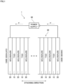
- Fig. 1 is a schematic view of a water electrolyzer 1 according to a preferred embodiment of the present invention.
- the water electrolyzer 1 is to produce hydrogen by solid polymer water electrolysis.
- the water electrolyzer 1 includes a cell stack 30 composed of a plurality of cells 10 and a plurality of separators 20, and a power supply 40 that applies a voltage to the cell stack 30.
- the cells 10 and the separators 20 are stacked alternately to form the cell stack 30.
- a direction in which the cells 10 and the separators 20 are stacked will be called a "stacking direction.”
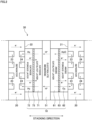
- Fig. 2 shows only one cell 10 and separators 20 in a pair arranged on both sides of this cell 10 schematically that form the cell stack 30 of the water electrolyzer 1.
- one cell 10 includes an electrolyte membrane 51, an anode catalyst layer 61, an anode porous layer 62, an anode ionomer layer 63, a cathode catalyst layer 71, a cathode porous layer 72, and a cathode ionomer layer 73.
- a stacked body composed of the electrolyte membrane 51, the anode catalyst layer 61, and the cathode catalyst layer 71 is called a catalyst-coated membrane (CCM).
- a stacked body composed of the electrolyte membrane 51, the anode catalyst layer 61, the anode porous layer 62, the anode ionomer layer 63, the cathode catalyst layer 71, the cathode porous layer 72, and the cathode ionomer layer 73 is called a membrane-electrode-assembly (MEA).
- MEA membrane-electrode-assembly corresponds to an example of an "electrode structure" of the present invention.
- the electrolyte membrane 51 is a membrane like a thin plate having ion conductivity (ion-exchange membrane).
- the electrolyte membrane 51 of the present preferred embodiment is a proton-exchange membrane that conducts hydrogen ions (H + ).
- a fluorine-based or hydrocarbon-based polymer electrolyte membrane is used as the electrolyte membrane 51. More specifically, a polymer electrolyte membrane containing perfluorocarbon sulfonic acid is used as the electrolyte membrane 51, for example.
- the electrolyte membrane 51 has a thickness from 5 to 200 ⁇ m, for example.
- the anode catalyst layer 61 is a catalyst layer that causes electrochemical reaction on an anode side.
- the anode catalyst layer 61 is formed on an anode-side surface of the electrolyte membrane 51.
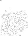
- Fig. 3 is a schematic view conceptually showing a part of the anode catalyst layer 61. As shown in Fig. 3 , the anode catalyst layer 61 contains a plurality of catalyst particles 611 and an ionomer 612.
- the catalyst particles 611 are particles for causing electrolysis of water.
- the catalyst particles 611 are made of iridium oxide (IrOx), platinum (Pt), an alloy of iridium (Ir) and ruthenium (Ru), or an alloy of iridium (Ir) and titanium dioxide (TiO 2 ), for example.
- the ionomer 612 is an electrolyte polymer covering the catalyst particles 611.
- the ionomer 612 functions to transport hydrogen ions in the anode catalyst layer 61 generated by electrolysis of water.
- nafion perfluorocarbon sulfonic acid
- the ionomer 612 has a polymer chain with an ion-exchange group such as a sulfone group.
- the hydrogen ions are combined with water in the anode catalyst layer 61 to become oxionium ions (H 3 O + ). These oxionium ions propagate through the ion-exchange group of the ionomer 612.
- the catalyst particles 611 and the ionomer 612 are first mixed with a solvent such as water or alcohol to prepare catalyst ink for anode. Then, the prepared catalyst ink is applied to the anode-side surface of the electrolyte membrane 51 and dried. As a result, the anode catalyst layer 61 is formed on the anode-side surface of the electrolyte membrane 51.
- water (H 2 O) is supplied to the anode catalyst layer 61.
- the power supply 40 applies a voltage between the anode catalyst layer 61 and the cathode catalyst layer 71.
- the water is electrolyzed into hydrogen ions (H + ), oxygen (O 2 ), and electrons (e - ) in the anode catalyst layer 61.
- the anode porous layer 62 is a layer for supplying water uniformly from the separator 20 to the anode catalyst layer 61 and for transporting oxygen and electrons generated in the anode catalyst layer 61 to the separator 20.
- the anode porous layer 62 is also called a porous transport layer (PTL).
- the anode porous layer 62 is stacked on an external side of the anode catalyst layer 61 (on the opposite side to the electrolyte membrane 51) across the anode ionomer layer 63 described later.
- the anode porous layer 62 has conductivity and is made of a porous material.
- the anode porous layer 62 is formed using a porous base material made of titanium metal or a titanium alloy, for example.
- Fig. 4 schematically shows a structure in the vicinity of a boundary between the anode catalyst layer 61 and the anode porous layer 62.
- catalyst particles 611 of the same type as those in the anode catalyst layer 61 are supported in the anode porous layer 62.
- the catalyst particles 611 made of iridium oxide (IrOx), platinum (Pt), an alloy of iridium (Ir) and ruthenium (Ru), or an alloy of iridium (Ir) and titanium dioxide (TiO 2 ) are supported in the anode porous layer 62.
- the weight of the catalyst particles 611 supported in the anode porous layer 62 is smaller than that of the catalyst particles 611 forming the anode catalyst layer 61.
- the catalyst particles 611 are supported particularly in a part of the anode porous layer 62 including a surface closer to the anode catalyst layer 61.
- Supporting the catalyst particles 611 in the anode porous layer 62 achieves reduction in the thickness of the anode catalyst layer 61 in the stacking direction while maintaining the quantity of the catalyst particles 611 as a whole. This allows oxygen generated in the anode catalyst layer 61 to flow easily from the anode catalyst layer 61 into the anode porous layer 62. As a result, it becomes possible to diffuse the oxygen with improved performance.
- the anode ionomer layer 63 is a layer of an ionomer 612 interposed between the anode catalyst layer 61 and the anode porous layer 62 in the stacking direction.
- the ionomer 612 forming the anode ionomer layer 63 is configured using the same nafion (perfluorocarbon sulfonic acid) as that forming the ionomer 612 in the anode catalyst layer 61 described above.
- the anode ionomer layer 63 is a layer composed only of the ionomer 612 formed separately from the ionomer 612 in the anode catalyst layer 61.
- the anode ionomer layer 63 is formed by applying or spraying the ionomer 612 to an external surface of the anode catalyst layer 61 (a surface closer to the anode porous layer 62) or to an internal surface of the anode porous layer 62 (a surface closer to the anode catalyst layer 61). Interposing the anode ionomer layer 63 improves tight contact property between the anode catalyst layer 61 and the anode porous layer 62. As a result, electrical contact resistance is reduced between the anode catalyst layer 61 and the anode porous layer 62.
- the cathode catalyst layer 71 is a catalyst layer that causes electrochemical reaction on a cathode side.
- the cathode catalyst layer 71 is formed on a cathode-side surface of the electrolyte membrane 51 (a surface on the opposite side to the surface where the anode catalyst layer 61 is formed).
- the cathode catalyst layer 71 contains a large number of carbon particles on which catalyst particles are supported.
- the catalyst particles are particles of platinum, for example.
- the catalyst particles may be prepared by mixing particles of a tiny amount of ruthenium or cobalt into particles of platinum.
- the carbon particles on which the catalyst particles are supported described above are first mixed with a solvent such as water or alcohol to prepare catalyst ink for cathode. Then, the prepared catalyst ink is applied to the cathode-side surface of the electrolyte membrane 51 and dried. As a result, the cathode catalyst layer 71 is formed on the cathode-side surface of the electrolyte membrane 51.
- the cathode porous layer 72 is a layer for transporting electrons from the separator 20 to the cathode catalyst layer 71 and for transporting hydrogen generated in the cathode catalyst layer 71 to the separator 20.
- the cathode porous layer 72 is also called a gas diffusion layer (GDL).
- the cathode porous layer 72 is stacked on an external side of the cathode catalyst layer 71 (on the opposite side to the electrolyte membrane 51) across the cathode ionomer layer 73 described later.
- the cathode porous layer 72 has conductivity and is made of a porous material.
- the cathode porous layer 72 is formed using a porous base material (carbon paper) made of carbon, for example.
- Catalyst particles of the same type as those in the cathode catalyst layer 71 are supported in the cathode porous layer 72.
- the cathode porous layer 72 supports carbon particles on which catalyst particles are supported.
- the catalyst particles are particles of platinum, for example.
- the weight of the catalyst particles supported in the cathode porous layer 72 is smaller than that of the catalyst particles in the cathode catalyst layer 71.
- the catalyst particles are supported particularly in a part of the cathode porous layer 72 including a surface closer to the cathode catalyst layer 71.
- Supporting the catalyst particles in the cathode porous layer 72 achieves reduction in the thickness of the cathode catalyst layer 71 in the stacking direction while maintaining the quantity of the catalyst particles as a whole. This allows hydrogen generated in the cathode catalyst layer 71 to flow easily from the cathode catalyst layer 71 into the cathode porous layer 72. As a result, it becomes possible to diffuse the hydrogen with improved performance.
- the cathode ionomer layer 73 is a layer of an ionomer 612 interposed between the cathode catalyst layer 71 and the cathode porous layer 72 in the stacking direction.
- the ionomer 612 forming the cathode ionomer layer 73 is configured using nafion (perfluorocarbon sulfonic acid).
- the cathode ionomer layer 73 is formed by applying or spraying the ionomer 612 to an external surface of the cathode catalyst layer 71 (a surface closer to the cathode porous layer 72) or to an internal surface of the cathode porous layer 72 (a surface closer to the cathode catalyst layer 71). Interposing the cathode ionomer layer 73 improves tight contact property between the cathode catalyst layer 71 and the cathode porous layer 72. This reduces electrical contact resistance between the cathode catalyst layer 71 and the cathode porous layer 72.
- the separator 20 is a layer for moving electrons between the cells 10 next to each other and for forming a passage for water, oxygen, and hydrogen.
- the separator 20 is interposed between the anode porous layer 62 of the cell 10 and the cathode porous layer 72 of the cell 10 next to the former cell 10.
- the separator 20 has conductivity and is made of a material impermeable to gas and liquid. For example. a metal plate is used as the separator 20.
- the separator 20 has an anode surface 21 contacting the anode porous layer 62, and a cathode surface 22 contacting the cathode porous layer 72.
- the anode surface 21 is provided with a plurality of anode grooves 23.
- Water is supplied from the outside of the cell stack 30 to the anode porous layer 62 through the anode grooves 23 of the separator 20.
- Oxygen generated in the anode catalyst layer 61 passes through the anode ionomer layer 63 and the anode porous layer 62 and is then output to the outside of the cell stack 30 through the anode grooves 23 of the separator 20.
- the cathode surface 22 of the separator 20 is provided with a plurality of cathode grooves 24. Hydrogen generated in the cathode catalyst layer 71 passes through the cathode ionomer layer 73 and the cathode porous layer 72 and is then output to the outside of the cell stack 30 through the cathode grooves 24 of the separator 20.
- the power supply 40 is a device that applies a voltage to the cell stack 30. As shown in Fig. 1 , the power supply 40 has a positive terminal electrically connected to the separator 20 at an end portion of the cell stack 30 farthest to the anode side. The power supply 40 has a negative terminal electrically connected to the separator 20 at an end portion of the cell stack 30 farthest to the cathode side. The power supply 40 applies a voltage to the cell stack 30 necessary for electrolysis of water.
- water is supplied from the anode grooves 23 of the separator 20 to the anode catalyst layer 61 through the anode porous layer 62 and the anode ionomer layer 63. Then, by the actions of a voltage applied from the power supply 40 and the catalyst particles 611 in the anode catalyst layer 61, the water is decomposed into hydrogen ions, oxygen, and electrons.
- the hydrogen ions propagate through the electrolyte membrane 51 into the cathode catalyst layer 71.
- the oxygen passes through the anode ionomer layer 63, the anode porous layer 62, and the anode grooves 23 and is then output to the outside of the cell stack 30.
- the electrons pass through the anode ionomer layer 63, the anode porous layer 62, and the separator 20 and then flow into the adjoining cell 10.
- these electrons pass through the cathode porous layer 72 and the cathode ionomer layer 73 to reach the cathode catalyst layer 71. Then, the hydrogen ions and the electrons are combined with each other to generate hydrogen in the cathode catalyst layer 71.
- the generated hydrogen passes through the cathode ionomer layer 73, the cathode porous layer 72, and the cathode grooves 24 and is then output to the outside of the cell stack 30. In this way, hydrogen is produced.
- the anode ionomer layer 63 is interposed between the anode catalyst layer 61 and the anode porous layer 62 in the water electrolyzer 1.
- tight contact property is improved between the anode catalyst layer 61 and the anode porous layer 62.
- This reduces electrical contact resistance between the anode catalyst layer 61 and the anode porous layer 62.
- electrons generated by electrolysis in the anode catalyst layer 61 it becomes possible for electrons generated by electrolysis in the anode catalyst layer 61 to flow efficiently from the anode catalyst layer 61 into the anode porous layer 62 during use of the water electrolyzer 1.
- the catalyst particles 611 are present both in the anode catalyst layer 61 and the anode porous layer 62. This achieves further reduction in electrical contact resistance between the anode catalyst layer 61 and the anode porous layer 62. As a result, it becomes possible for electrons to flow from the anode catalyst layer 61 into the anode porous layer 62 more efficiently.
- the cathode ionomer layer 73 is interposed between the cathode catalyst layer 71 and the cathode porous layer 72.
- tight contact property is improved between the cathode catalyst layer 71 and the cathode porous layer 72.
- This reduces electrical contact resistance between the cathode catalyst layer 71 and the cathode porous layer 72.
- the catalyst particles are present both in the cathode catalyst layer 71 and the cathode porous layer 72. This achieves further reduction in electrical contact resistance between the cathode catalyst layer 71 and the cathode porous layer 72. As a result, it becomes possible for electrons to flow from the cathode porous layer 72 into the cathode catalyst layer 71 more efficiently.
- the anode ionomer layer 63 is interposed between the anode catalyst layer 61 and the anode porous layer 62 and the cathode ionomer layer 73 is interposed between the cathode catalyst layer 71 and the cathode porous layer 72.
- an ionomer layer be provided on each of an anode side and a cathode side.
- the ionomer layer only has to be provided between a catalyst layer and a porous layer on at least one of an anode side and a cathode side of an electrode structure.
- the catalyst particles 611 are supported in the anode porous layer 62. However, it is not essential that the catalyst particles 611 be supported in the anode porous layer 62. Furthermore, in the above-described preferred embodiment, the catalyst particles are supported in the cathode porous layer 72. However, it is not essential that the catalyst particles be supported in the cathode porous layer 72. For this reason, an ionomer layer may be provided between a catalyst layer and a porous layer where catalyst particles are not supported.
- LOHC liquid organic hydrogen carrier
Landscapes
- Chemical & Material Sciences (AREA)
- Organic Chemistry (AREA)
- Engineering & Computer Science (AREA)
- Materials Engineering (AREA)
- Chemical Kinetics & Catalysis (AREA)
- Electrochemistry (AREA)
- Metallurgy (AREA)
- Inorganic Chemistry (AREA)
- General Chemical & Material Sciences (AREA)
- Electrodes For Compound Or Non-Metal Manufacture (AREA)
- Electrolytic Production Of Non-Metals, Compounds, Apparatuses Therefor (AREA)
Applications Claiming Priority (1)
| Application Number | Priority Date | Filing Date | Title |
|---|---|---|---|
| JP2023045864A JP2024135261A (ja) | 2023-03-22 | 2023-03-22 | 電極構造体および水電解装置 |
Publications (2)
| Publication Number | Publication Date |
|---|---|
| EP4435146A2 true EP4435146A2 (de) | 2024-09-25 |
| EP4435146A3 EP4435146A3 (de) | 2024-10-30 |
Family
ID=89661245
Family Applications (1)
| Application Number | Title | Priority Date | Filing Date |
|---|---|---|---|
| EP24152545.0A Pending EP4435146A3 (de) | 2023-03-22 | 2024-01-18 | Elektrodenstruktur und wasserelektrolyseur |
Country Status (4)
| Country | Link |
|---|---|
| US (1) | US20240318329A1 (de) |
| EP (1) | EP4435146A3 (de) |
| JP (1) | JP2024135261A (de) |
| AU (1) | AU2024200352B2 (de) |
Citations (1)
| Publication number | Priority date | Publication date | Assignee | Title |
|---|---|---|---|---|
| JP2022023996A (ja) | 2021-11-05 | 2022-02-08 | 東京瓦斯株式会社 | 電気化学デバイス |
Family Cites Families (3)
| Publication number | Priority date | Publication date | Assignee | Title |
|---|---|---|---|---|
| US6867159B2 (en) * | 2002-12-04 | 2005-03-15 | Ballard Power Systems Inc. | Application of an ionomer layer to a substrate and products related thereto |
| JP7664170B2 (ja) * | 2019-10-31 | 2025-04-17 | 株式会社カーリット | 水電解用の触媒担持多孔質基体、水電解用電極、気体拡散層、水電解用スタックセル、及び、水電解用セルモジュール |
| EP4055211A1 (de) * | 2019-11-04 | 2022-09-14 | TotalEnergies OneTech | Katalysator-ionomer-systeme und verfahren zur gasphasenelektrolyse |
-
2023
- 2023-03-22 JP JP2023045864A patent/JP2024135261A/ja active Pending
-
2024
- 2024-01-18 EP EP24152545.0A patent/EP4435146A3/de active Pending
- 2024-01-19 AU AU2024200352A patent/AU2024200352B2/en active Active
- 2024-03-01 US US18/593,013 patent/US20240318329A1/en active Pending
Patent Citations (1)
| Publication number | Priority date | Publication date | Assignee | Title |
|---|---|---|---|---|
| JP2022023996A (ja) | 2021-11-05 | 2022-02-08 | 東京瓦斯株式会社 | 電気化学デバイス |
Also Published As
| Publication number | Publication date |
|---|---|
| AU2024200352B2 (en) | 2025-06-05 |
| US20240318329A1 (en) | 2024-09-26 |
| EP4435146A3 (de) | 2024-10-30 |
| JP2024135261A (ja) | 2024-10-04 |
| AU2024200352A1 (en) | 2024-10-10 |
Similar Documents
| Publication | Publication Date | Title |
|---|---|---|
| US7858263B2 (en) | Solid polymer electrolyte fuel cell and method for manufacturing the same | |
| US6847518B2 (en) | Membrane electrode assembly for polymer electrolyte fuel cell | |
| US7226689B2 (en) | Method of making a membrane electrode assembly for electrochemical fuel cells | |
| EP4177380B1 (de) | Membran-elektrodenanordnung, wasserstofferzeugungsvorrichtung, verfahren zur herstellung einer katalysatortinte und verfahren zur herstellung einer membran-elektrodenanordnung | |
| KR20040099149A (ko) | 연료 전지 | |
| EP4343031A2 (de) | Separator und wasserelektrolyseur | |
| EP4148842A1 (de) | Membran-elektroden-einheit, polymerelektrolyt-brennstoffzelle, verfahren zur herstellung einer katalysatortinte und verfahren zur herstellung einer membran-elektrodenanordnung | |
| US20080286632A1 (en) | Membrane Electrode Assemblies for Polymer Electrolyte Hydrogen and Direct Methanol Fuel Cells and Methods for Their Production | |
| US20240234747A9 (en) | Method for producing catalyst layers for fuel cells | |
| EP4435146A2 (de) | Elektrodenstruktur und wasserelektrolyseur | |
| JP2002110190A (ja) | 燃料電池 | |
| EP4442861A1 (de) | Elektrodenstruktur und wasserelektrolyseur | |
| EP4534729A2 (de) | Elektrodenstruktur | |
| EP4534730A2 (de) | Elektrodenstruktur | |
| EP4534731A2 (de) | Elektrodenstruktur | |
| US20060068269A1 (en) | Electrode structure for solid polymer type fuel cell | |
| EP4541941A1 (de) | Elektrodenstruktur, gasdiffusionsschicht und wasserelektrolyseur | |
| JP2006185882A (ja) | 金属製セパレータを用いた燃料電池の運転方法、および金属製セパレータを用いた燃料電池を有する発電装置 | |
| JP2026017255A (ja) | 膜・触媒層接合体、水電解装置、および膜・触媒層接合体の製造方法 | |
| JP2005228690A (ja) | 燃料電池の触媒担持方法 |
Legal Events
| Date | Code | Title | Description |
|---|---|---|---|
| PUAI | Public reference made under article 153(3) epc to a published international application that has entered the european phase |
Free format text: ORIGINAL CODE: 0009012 |
|
| STAA | Information on the status of an ep patent application or granted ep patent |
Free format text: STATUS: THE APPLICATION HAS BEEN PUBLISHED |
|
| AK | Designated contracting states |
Kind code of ref document: A2 Designated state(s): AL AT BE BG CH CY CZ DE DK EE ES FI FR GB GR HR HU IE IS IT LI LT LU LV MC ME MK MT NL NO PL PT RO RS SE SI SK SM TR |
|
| PUAL | Search report despatched |
Free format text: ORIGINAL CODE: 0009013 |
|
| AK | Designated contracting states |
Kind code of ref document: A3 Designated state(s): AL AT BE BG CH CY CZ DE DK EE ES FI FR GB GR HR HU IE IS IT LI LT LU LV MC ME MK MT NL NO PL PT RO RS SE SI SK SM TR |
|
| RIC1 | Information provided on ipc code assigned before grant |
Ipc: C25B 3/25 20210101ALI20240926BHEP Ipc: C25B 3/03 20210101ALI20240926BHEP Ipc: C25B 15/08 20060101ALI20240926BHEP Ipc: C25B 11/081 20210101ALI20240926BHEP Ipc: C25B 11/054 20210101ALI20240926BHEP Ipc: C25B 11/031 20210101ALI20240926BHEP Ipc: C25B 9/77 20210101ALI20240926BHEP Ipc: C25B 1/04 20210101AFI20240926BHEP |
|
| STAA | Information on the status of an ep patent application or granted ep patent |
Free format text: STATUS: REQUEST FOR EXAMINATION WAS MADE |
|
| 17P | Request for examination filed |
Effective date: 20250422 |