EP4177616A1 - Kurzschlusserkennung und -schutz für ein bauelement mit isoliertem gate durch überwachung und kontrolle der gatespannung - Google Patents
Kurzschlusserkennung und -schutz für ein bauelement mit isoliertem gate durch überwachung und kontrolle der gatespannung Download PDFInfo
- Publication number
- EP4177616A1 EP4177616A1 EP22205928.9A EP22205928A EP4177616A1 EP 4177616 A1 EP4177616 A1 EP 4177616A1 EP 22205928 A EP22205928 A EP 22205928A EP 4177616 A1 EP4177616 A1 EP 4177616A1
- Authority
- EP
- European Patent Office
- Prior art keywords
- gate
- voltage
- power transistor
- transistor
- short
- Prior art date
- Legal status (The legal status is an assumption and is not a legal conclusion. Google has not performed a legal analysis and makes no representation as to the accuracy of the status listed.)
- Granted
Links
Images
Classifications
-
- G—PHYSICS
- G01—MEASURING; TESTING
- G01R—MEASURING ELECTRIC VARIABLES; MEASURING MAGNETIC VARIABLES
- G01R19/00—Arrangements for measuring currents or voltages or for indicating presence or sign thereof
- G01R19/165—Indicating that current or voltage is either above or below a predetermined value or within or outside a predetermined range of values
- G01R19/16533—Indicating that current or voltage is either above or below a predetermined value or within or outside a predetermined range of values characterised by the application
- G01R19/16538—Indicating that current or voltage is either above or below a predetermined value or within or outside a predetermined range of values characterised by the application in AC or DC supplies
- G01R19/16547—Indicating that current or voltage is either above or below a predetermined value or within or outside a predetermined range of values characterised by the application in AC or DC supplies voltage or current in AC supplies
-
- H—ELECTRICITY
- H03—ELECTRONIC CIRCUITRY
- H03K—PULSE TECHNIQUE
- H03K17/00—Electronic switching or gating, i.e. not by contact-making and –breaking
- H03K17/08—Modifications for protecting switching circuit against overcurrent or overvoltage
- H03K17/081—Modifications for protecting switching circuit against overcurrent or overvoltage without feedback from the output circuit to the control circuit
- H03K17/08104—Modifications for protecting switching circuit against overcurrent or overvoltage without feedback from the output circuit to the control circuit in field-effect transistor switches
-
- G—PHYSICS
- G01—MEASURING; TESTING
- G01R—MEASURING ELECTRIC VARIABLES; MEASURING MAGNETIC VARIABLES
- G01R15/00—Details of measuring arrangements of the types provided for in groups G01R17/00 - G01R29/00, G01R33/00 - G01R33/26 or G01R35/00
- G01R15/14—Adaptations providing voltage or current isolation, e.g. for high-voltage or high-current networks
- G01R15/16—Adaptations providing voltage or current isolation, e.g. for high-voltage or high-current networks using capacitive devices
-
- G—PHYSICS
- G01—MEASURING; TESTING
- G01R—MEASURING ELECTRIC VARIABLES; MEASURING MAGNETIC VARIABLES
- G01R19/00—Arrangements for measuring currents or voltages or for indicating presence or sign thereof
- G01R19/165—Indicating that current or voltage is either above or below a predetermined value or within or outside a predetermined range of values
-
- H—ELECTRICITY
- H03—ELECTRONIC CIRCUITRY
- H03K—PULSE TECHNIQUE
- H03K17/00—Electronic switching or gating, i.e. not by contact-making and –breaking
- H03K17/08—Modifications for protecting switching circuit against overcurrent or overvoltage
- H03K17/081—Modifications for protecting switching circuit against overcurrent or overvoltage without feedback from the output circuit to the control circuit
- H03K17/0812—Modifications for protecting switching circuit against overcurrent or overvoltage without feedback from the output circuit to the control circuit by measures taken in the control circuit
- H03K17/08128—Modifications for protecting switching circuit against overcurrent or overvoltage without feedback from the output circuit to the control circuit by measures taken in the control circuit in composite switches
-
- G—PHYSICS
- G01—MEASURING; TESTING
- G01R—MEASURING ELECTRIC VARIABLES; MEASURING MAGNETIC VARIABLES
- G01R19/00—Arrangements for measuring currents or voltages or for indicating presence or sign thereof
- G01R19/0092—Measuring current only
-
- G—PHYSICS
- G01—MEASURING; TESTING
- G01R—MEASURING ELECTRIC VARIABLES; MEASURING MAGNETIC VARIABLES
- G01R19/00—Arrangements for measuring currents or voltages or for indicating presence or sign thereof
- G01R19/165—Indicating that current or voltage is either above or below a predetermined value or within or outside a predetermined range of values
- G01R19/16504—Indicating that current or voltage is either above or below a predetermined value or within or outside a predetermined range of values characterised by the components employed
- G01R19/16519—Indicating that current or voltage is either above or below a predetermined value or within or outside a predetermined range of values characterised by the components employed using FET's
-
- G—PHYSICS
- G01—MEASURING; TESTING
- G01R—MEASURING ELECTRIC VARIABLES; MEASURING MAGNETIC VARIABLES
- G01R31/00—Arrangements for testing electric properties; Arrangements for locating electric faults; Arrangements for electrical testing characterised by what is being tested not provided for elsewhere
- G01R31/50—Testing of electric apparatus, lines, cables or components for short-circuits, continuity, leakage current or incorrect line connections
- G01R31/52—Testing for short-circuits, leakage current or ground faults
Definitions
- the field of the invention is that of power electronics module controls making it possible to control the operation of power electronic components.
- power modules represent electronic components dealing with high powers and therefore require particular attention in their design and monitoring during their life and use.
- the invention relates to the protection of insulated-gate power components such as IGBT (Insulated Gate Bipolar Transistor) insulated-gate power transistors or even MOSFET (Metal Oxide Semiconductor Field) insulated-gate field-effect transistors. Effect Transistor).
- IGBT Insulated Gate Bipolar Transistor
- MOSFET Metal Oxide Semiconductor Field
- the verification of the current flowing through the two terminals mentioned above is done through monitoring the voltage or the current directly between the two terminals mentioned, i.e. at the level of the conduction channel of a transistor.
- the invention aims to overcome all or part of the problems mentioned above by proposing a device for detecting a short-circuit current between the collector (or the drain) and the emitter (or the source) of the simple power transistor , compact and having a relatively low production cost.
- the subject of the invention is a power stage comprising a power transistor controlled via a driver, the power transistor comprising three terminals including a collector c, an emitter e and a gate g connected to the driver, the power stage also comprising a device for detecting a DC short-circuit current between the collector c and the emitter e, the detection device comprising a voltage sensor capable of detecting a voltage Vge at the gate g of the power transistor outside a predefined voltage range.
- the detection device comprises an energy storage device configured to deliver an additional voltage to the gate g if the equivalent capacitance of the gate Cge is discharged.
- the energy storage device is an inductor positioned between the driver and the gate g of the power transistor.
- the power stage comprises a voltage reducer able to reduce the voltage Vge at the gate g down to a threshold voltage.
- the power stage comprises a recorder capable of recording an operating fault of the power transistor.
- the invention has the advantage of allowing analysis of the current between the collector and the emitter of a power transistor by monitoring the gate voltage of the power transistor via a compact detection device and simple in design.
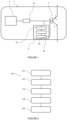
- FIG.1 there figure 1 represents a power stage comprising a power transistor and a device for detecting a short-circuit current according to the invention
- FIG.2 there picture 2 represents a method for detecting a short-circuit current between a drain and a source of a power transistor according to the invention.
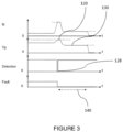
- FIG.3 there picture 3 represents the method of detecting a short-circuit current via a timing diagram.
- FIG. 1 represents a power stage 2 comprising a power transistor 4 controlled via a driver 6.
- the power transistor 4 comprises three terminals including a collector c, an emitter e and a gate g connected to the driver 6.
- the transistor power 4 is an insulated gate bipolar transistor (IGBT, English Insulated Gate Bipolar Transistor ) .
- the power transistor 4 is a field-effect transistor (in English, metal oxide semiconductor Field-effect transistor or MOSFET ) and therefore comprises a drain, a source and a gate connected to the driver 6. Consequently, for a field effect transistor, the drain can be likened to the collector c, the source can be likened to the emitter e.
- the type 1 short-circuit and the type 2 short-circuit are both linked to a circuit external to the power transistor 4, forming a closed electric loop and comprising an electric load, connected to the power transistor 4 through the collector c and the emitter e.
- a type 1 short-circuit is a short-circuit appearing in this external circuit when the power transistor 4 is already in conduction while a type 2 short-circuit is a short-circuit already present in the circuit external before the conduction of the power transistor 4 is established.
- the power stage 2 comprises a device 8 for detecting a short-circuit current dc between the collector c and the emitter e.
- the detection device 8 comprises a voltage sensor 82 capable of detecting and measuring the voltage between the gate g and the emitter e named Vge at the level of the gate g of the power transistor 4. More precisely, the voltage sensor 82 is configured to compare this gate voltage Vge measurement to a defined voltage range, and signal if the gate voltage Vge measurement is outside the predefined voltage range.
- the presence of a short-circuit in the power transistor 4 and particularly between the collector c and the emitter e can result in a significant increase in the intensity of the current between these two terminals of the power transistor 4 and induces the degradation of the power stage 2.
- ⁇ Vg represents the voltage variation Vge at the gate
- ⁇ Ids represents the variation of the current between the collector c and the emitter e
- Gm represents the transconductance of the power transistor 4.
- the transconductance Gm is equal to 300 Siemens for example.
- the voltage Vge at the gate also undergoes an increase in the voltage measurement carried out by means of a voltage sensor 82.
- the voltage sensor 82 which is connected directly to the gate g, therefore makes it possible to measure the voltage Vge at the gate g so as to be able to detect a DC short-circuit current between the collector c and emitter e of power transistor 4.
- the predefined voltage range in which the voltage Vge of the gate g is comprised is a voltage range comprised between 0 Volts and +20 Volts.
- this predefined voltage range is a voltage range comprised between 2 volts and 20 volts in the case of use of a MOSFET insulated-gate field-effect transistor.
- the predefined voltage range is a voltage range between 5 Volts and 20 Volts.
- the short-circuit may also be present before power transistor 4 is turned on in the case of a type 2 short-circuit.
- an abnormal current or in other words a short-circuit current
- the measurable gate voltage value does not increase as quickly and is not as large as for a type 1 short-circuit. Therefore, the simple measurement of the gate voltage Vge is no longer sufficient since this measurement can be done late.
- the equivalent capacitance seen from the gate g of the power transistor remains constant and of low value, ie around ten times lower than when a “normal” current flows through the power transistor.
- the value of the capacitance, seen from the gate g is increased, in particular because of the Miller effect, when the voltage measured at collector c is low.
- This equivalent capacitance measured at the gate g is of high value, and generally greater than one microfarad, at switching instants. And, in short-circuit, the instant of switching then does not impact the value of the equivalent gate capacitance.
- the value of the equivalent gate capacitance remains constant and of low value, i.e. less than one hundred nanofarads. This evolution can be understood as being the evolution of the charges at the gate.
- the detection device 8 comprises a capacitance measurement sensor 83 capable of detecting and measuring an equivalent capacitance value Cge of the gate g at the level of the gate g of the transistor of power 4. More precisely, the capacitance sensor 83 is configured to compare this gate equivalent capacitance measurement Cge with a predefined capacitance value, and signal if the gate equivalent capacitance measurement Cge is lower than the predefined capacitance value.
- the capacitance measurement sensor 83 when the equivalent capacitance of the gate Cge, between the gate g and the conduction channel, is discharged, the capacitance measurement sensor 83 is capable of detecting this equivalent capacitance value Cge, measuring this equivalent capacitance value Cge , compare this equivalent capacitance value Cge with the normally measurable predefined capacitance value and report the malfunction.
- the equivalent capacitance of the gate Cge in a nominal operation of the power transistor 4, that is to say at the instants of switching, the equivalent capacitance of the gate Cge is transiently of high value, that is to say for example greater than 1 ⁇ F.
- the equivalent capacitance of the gate Cge is of low value, that is to say for example approximately 100 nF.
- the predefined capacitance value may be a capacitance value of 100 nF.
- the capacitance measurement sensor 83 can be a Wheatstone bridge.
- VS age Q age V age
- Q ge represents the gate charge
- V ge represents the voltage between the gate and the emitter.
- the charge Qge can be defined by integrating, with respect to time, the intensity of the current crossing the grid g.
- the value of the voltage at the gate Vge is already known through the voltage sensor 82.
- the capacitance measurement sensor 83 can also be a device for measuring the intensity of the current at the gate g configured to determine, according to the previous formula, the equivalent capacitance value of the gate Cge.
- the detection device 8 also comprises an energy storage device 84 configured to deliver an additional voltage to the gate g when the equivalent capacitance value measured at the gate Cge by the capacitance measurement sensor 83 is lower than the value of capacity preset to grid g.
- an energy storage device 84 configured to deliver an additional voltage to the gate g when the equivalent capacitance value measured at the gate Cge by the capacitance measurement sensor 83 is lower than the value of capacity preset to grid g.
- the capacitance measurement sensor 83 controls the storage device of energy 84 so that the energy storage device 84 releases an additional voltage to the gate g.
- the release of this additional voltage at the gate g then makes it possible to generate an overvoltage at the level of the gate g.
- the voltage Vge between the gate g and the emitter e increases in proportion to the additional voltage delivered by the storage device 84 until it exceeds the predefined voltage range. Consequently, the voltage sensor 82 detects that the voltage Vge at the level of the gate g of the power transistor 4 is outside the predefined voltage range and therefore signals a short-circuit in the power transistor 4 making it possible to open the power transistor 4 before degradation of its components.
- Energy storage device 84 is positioned between driver 6 and gate g of power transistor 4 so as to be able to deliver the additional voltage to gate g.
- this additional voltage is the voltage necessary for the sum of the voltage measured at the gate g and of the additional voltage to be greater than the maximum voltage value of the predefined voltage range.
- the energy storage device 84 is an inductor, with an inductance value of around 100 nH, positioned between the driver 6 and the gate g of the power transistor 4.
- the inductor has the advantage of being a passive component making it possible to respond directly to a square-wave signal supplied by driver 6 and to allow the storage and release of sufficient energy to induce an overvoltage, when the equivalent capacitance seen from the gate of power transistor 4 is low and discharged.
- the storage device 84 is an active generator making it possible to generate an additional voltage at the gate and controlled by information from the driver 6.
- the storage device 84 is likened to an inductor 84.
- the inductor 84 is positioned in series between the driver 6 and the gate g so as to produce a resonant circuit RLC between the driver 6, via a resistor included in the driver 6, the inductance 84 and the capacitance of the gate g and therefore know the damping of the system.
- the following relation makes it possible to highlight an under-damping of the resonant circuit RLC allowing the inductor 84 to inject the additional voltage to the gate g according to the condition: Rg 2 Cge _ CC I ⁇ 1
- Rg represents the resistance of driver 6 in the RLC resonant circuit
- Cge_cc represents the equivalent capacitance of gate g when power transistor 4 experiences a short circuit
- L represents the inductance value of inductor 84.
- the inductor 84 has the advantage of allowing an additional supply of voltage at the level of the gate g of the power transistor so as to highlight the fact that the value of the voltage Vge of the gate g is not not included in the voltage range and therefore the presence of a DC short-circuit current during this transition phase of the power transistor 4.
- the power stage 2 comprises a voltage reducer 86 able to reduce the voltage Vge at the gate g down to a threshold voltage, when a DC short-circuit current is detected between the collector c and the transmitter e via the voltage sensor 82. More precisely, when the voltage Vge at the gate g detected by the voltage sensor 82 is not included in the predefined voltage range, the voltage reducer 86 makes it possible to reduce this voltage Vge at the gate g in order to be included in the voltage range.
- the threshold voltage can be a voltage less than 20 volts and/or greater than the voltage at which the power transistor begins to conduct, called Vgsth, and is preferably a voltage of 10 volts.
- the power stage 2 also includes a recorder 88 capable of recording the short-circuit of the power transistor 4.
- the recorder 88 is a capacitor which discharges following the short-circuit in order to put evidence of an operating fault in power transistor 4.
- Reducing the voltage (step 130) at gate g of power transistor 4 can induce automatic opening (step 140) of power transistor 4.
- this opening (step 140) can be controlled. Nevertheless, the control of the opening 140 of the power transistor 4 must be prompt.
- the detection method 100 can also comprise a step of restoring (step 110) additional energy upstream of the detection step 120 if the equivalent capacitance of the gate Cge is discharged and lower than the predefined capacitance, i.e. that is to say, for example, a capacitance of about 100 nF.
- the step of restitution 110 of the energy stored at the gate g makes it possible to supply the additional energy highlighting a short-circuit during the switching of the power transistor 4.
- the detection method 100 can also comprise, following the detection step 120, a step of recording the fault (step 128) of the power transistor 4.
- the detection method 100 can also be interpreted according to the timing diagram shown in picture 3 . Indeed, a short-circuit current at the level of the power transistor 4 can be interpreted as a strong increase in the current Ip passing through the power transistor 4. However, in the case of a type 1 short-circuit, this increase of the current is accompanied by an increase in the voltage Vge at the gate g of the power transistor 4. Consequently, the detection 120 takes place when the voltage Vge is greater than 20 volts for example. Then follows, in order not to damage the power transistor 4, the reduction of the voltage Vge (step 130) at the gate g of the power transistor 4 to the predefined voltage, such as for example 10 Volts and the opening 140 of the power transistor 4.
- the predefined voltage such as for example 10 Volts and the opening 140 of the power transistor 4.
- the restitution 110 of sufficient energy to induce the overvoltage if the equivalent capacitance of the gate Cge is discharged and lower than the predefined capacitance c′ that is to say, for example, a capacitance of approximately 100 nF, makes it possible to generate the detection 120 of this overvoltage at the gate.
- the fault recording step 128 makes it possible, upon detection 120 of the operating fault of the power transistor 4, to memorize the fault in real time.
- the invention therefore proposes to integrate a voltage sensor at the gate of the power transistor in order to detect an abnormal voltage, that is to say a voltage outside a predefined voltage range for the gate g and to integrate a means making it possible to store and restore sufficient energy to induce detection of an abnormal voltage, when the equivalent capacitance Cge seen from the gate of the power transistor 4 is discharged for the case of a short-circuit type 2.
- the invention therefore has the ability to detect a short-circuit in the power transistor from the measurement of the voltage at the gate of the power transistor.
Landscapes
- Physics & Mathematics (AREA)
- General Physics & Mathematics (AREA)
- Engineering & Computer Science (AREA)
- Power Engineering (AREA)
- Power Conversion In General (AREA)
Applications Claiming Priority (1)
| Application Number | Priority Date | Filing Date | Title |
|---|---|---|---|
| FR2111832A FR3128995B1 (fr) | 2021-11-08 | 2021-11-08 | Détection et protection de court-circuit d’un composant à grille isolée par monitoring et contrôle de la tension de grille. |
Publications (2)
| Publication Number | Publication Date |
|---|---|
| EP4177616A1 true EP4177616A1 (de) | 2023-05-10 |
| EP4177616B1 EP4177616B1 (de) | 2026-01-07 |
Family
ID=80735878
Family Applications (1)
| Application Number | Title | Priority Date | Filing Date |
|---|---|---|---|
| EP22205928.9A Active EP4177616B1 (de) | 2021-11-08 | 2022-11-07 | Kurzschlusserkennung und -schutz für ein bauelement mit isoliertem gate durch überwachung und kontrolle der gatespannung |
Country Status (3)
| Country | Link |
|---|---|
| US (1) | US12278621B2 (de) |
| EP (1) | EP4177616B1 (de) |
| FR (1) | FR3128995B1 (de) |
Cited By (1)
| Publication number | Priority date | Publication date | Assignee | Title |
|---|---|---|---|---|
| EP4637034A1 (de) * | 2024-04-17 | 2025-10-22 | STMicroelectronics International N.V. | Transistorsteuerschaltung |
Families Citing this family (2)
| Publication number | Priority date | Publication date | Assignee | Title |
|---|---|---|---|---|
| JP7552550B2 (ja) * | 2021-10-18 | 2024-09-18 | 株式会社デンソー | スイッチの過電流検出装置 |
| FR3133283B1 (fr) * | 2022-03-02 | 2024-12-13 | Thales Sa | Pilote pour transistor à grille isolée avec circuit de compensation des temps de retard |
Citations (6)
| Publication number | Priority date | Publication date | Assignee | Title |
|---|---|---|---|---|
| US20120248864A1 (en) * | 2011-02-28 | 2012-10-04 | General Electric Company, A New York Corporation | System and Method for Operating Inverters |
| JP2015053749A (ja) * | 2013-09-05 | 2015-03-19 | 三菱電機株式会社 | 電力用半導体素子の駆動回路 |
| CN108508342A (zh) * | 2018-05-28 | 2018-09-07 | 中国科学院上海微系统与信息技术研究所 | 一种igbt短路过流检测电路 |
| US10141923B2 (en) * | 2016-08-25 | 2018-11-27 | Toyota Motor Engineering & Manufacturing North America, Inc. | System and method for eliminating gate voltage oscillation in paralleled power semiconductor switches |
| US20200212906A1 (en) * | 2017-07-28 | 2020-07-02 | Mitsubishi Electric Corporation | Drive circuit for power semiconductor element |
| US20210293874A1 (en) * | 2020-03-23 | 2021-09-23 | Semiconductor Components Industries, Llc | Igbt/mosfet fault protection |
Family Cites Families (3)
| Publication number | Priority date | Publication date | Assignee | Title |
|---|---|---|---|---|
| SE515457C2 (sv) * | 1996-09-20 | 2001-08-06 | Abb Research Ltd | Metod och anordning vid effektransistor |
| US9331188B2 (en) * | 2014-09-11 | 2016-05-03 | Avago Technologies General Ip (Singapore) Pte. Ltd. | Short-circuit protection circuits, system, and method |
| DE112016002719B4 (de) * | 2015-06-16 | 2025-09-18 | Mitsubishi Electric Corporation | Treiber-steuerungsschaltung für leistungshalbleiter-element |
-
2021
- 2021-11-08 FR FR2111832A patent/FR3128995B1/fr active Active
-
2022
- 2022-11-07 EP EP22205928.9A patent/EP4177616B1/de active Active
- 2022-11-07 US US17/982,436 patent/US12278621B2/en active Active
Patent Citations (6)
| Publication number | Priority date | Publication date | Assignee | Title |
|---|---|---|---|---|
| US20120248864A1 (en) * | 2011-02-28 | 2012-10-04 | General Electric Company, A New York Corporation | System and Method for Operating Inverters |
| JP2015053749A (ja) * | 2013-09-05 | 2015-03-19 | 三菱電機株式会社 | 電力用半導体素子の駆動回路 |
| US10141923B2 (en) * | 2016-08-25 | 2018-11-27 | Toyota Motor Engineering & Manufacturing North America, Inc. | System and method for eliminating gate voltage oscillation in paralleled power semiconductor switches |
| US20200212906A1 (en) * | 2017-07-28 | 2020-07-02 | Mitsubishi Electric Corporation | Drive circuit for power semiconductor element |
| CN108508342A (zh) * | 2018-05-28 | 2018-09-07 | 中国科学院上海微系统与信息技术研究所 | 一种igbt短路过流检测电路 |
| US20210293874A1 (en) * | 2020-03-23 | 2021-09-23 | Semiconductor Components Industries, Llc | Igbt/mosfet fault protection |
Cited By (2)
| Publication number | Priority date | Publication date | Assignee | Title |
|---|---|---|---|---|
| EP4637034A1 (de) * | 2024-04-17 | 2025-10-22 | STMicroelectronics International N.V. | Transistorsteuerschaltung |
| FR3161520A1 (fr) * | 2024-04-17 | 2025-10-24 | Stmicroelectronics International N.V. | Circuit de commande d’un transistor |
Also Published As
| Publication number | Publication date |
|---|---|
| US20230146986A1 (en) | 2023-05-11 |
| FR3128995A1 (fr) | 2023-05-12 |
| FR3128995B1 (fr) | 2023-10-27 |
| US12278621B2 (en) | 2025-04-15 |
| EP4177616B1 (de) | 2026-01-07 |
Similar Documents
| Publication | Publication Date | Title |
|---|---|---|
| EP4177616B1 (de) | Kurzschlusserkennung und -schutz für ein bauelement mit isoliertem gate durch überwachung und kontrolle der gatespannung | |
| EP0462023B1 (de) | Statischer Schalter | |
| EP0593660B1 (de) | Einrichtung zum Detektieren der Dysfunktion eines Verbrauchers wie ein Magnetron | |
| FR2869689A1 (fr) | Procede et dispositif pour tester au moins une branche de del | |
| FR2567340A1 (fr) | Relais a semi-conducteur protege contre les surcharges de courant | |
| FR2642176A1 (fr) | Dispositif et procede de detection du passage d'un courant dans un transistor mos | |
| CA2315896C (fr) | Circuit electronique de surveillance de tension electrique | |
| FR2864172A1 (fr) | Circuit de detection d'ionisation a double etage | |
| EP3386053A1 (de) | Verfahren zum schutz gegen eine überspannung in einem schwingkreis | |
| FR2825470A1 (fr) | Procede et dispositif pour detecter un defaut de court-circuit de charge et dispositif de direction a assistance electrique | |
| EP0635923A1 (de) | Schutzschaltung gegen Überspannungen hoher Energie mit geregelter Spannungsbegrenzung | |
| FR2731111A1 (fr) | Dispositif de protection d'elements rechargeables et transistor mosfet equipant ce dispositif | |
| FR2842664A1 (fr) | Chargeur pour batterie | |
| FR2467407A1 (fr) | Dispositif de mesure des valeurs cretes d'un phenomene non periodique a recurrence faible | |
| EP0506531B1 (de) | Schaltung zur Überwachung eines oberen Schwellwertes einer Versorgungsspannung | |
| FR3116161A1 (fr) | Détecteur de court-circuit pour transistor de puissance par surveillance du courant de sa grille | |
| FR2865885A1 (fr) | Dispositif de protection pour alimentation a decoupage et dispositif d'eclairage de vehicule. | |
| EP0457397B1 (de) | Schaltungsanordnung zur Regelung des Leitungsstroms in einem Telefonapparat | |
| US20250321294A1 (en) | Emergency starting power supply with contact impedance detection | |
| EP0785703B1 (de) | Regelvorrichtung einer Niederdruckleuchtstofflampe | |
| WO2024133276A1 (fr) | Generation electrique ac comprenant un dispositif de protection de surtension non inductive | |
| FR2830692A1 (fr) | Declencheur electronique comportant un dispositif de test des capteurs de courant | |
| EP2372913A1 (de) | Eltektronischer Systemschutz | |
| WO2009060131A1 (fr) | Banc d'essai | |
| EP4478070A1 (de) | Kurzschlussdetektionsvorrichtung |
Legal Events
| Date | Code | Title | Description |
|---|---|---|---|
| PUAI | Public reference made under article 153(3) epc to a published international application that has entered the european phase |
Free format text: ORIGINAL CODE: 0009012 |
|
| STAA | Information on the status of an ep patent application or granted ep patent |
Free format text: STATUS: THE APPLICATION HAS BEEN PUBLISHED |
|
| AK | Designated contracting states |
Kind code of ref document: A1 Designated state(s): AL AT BE BG CH CY CZ DE DK EE ES FI FR GB GR HR HU IE IS IT LI LT LU LV MC ME MK MT NL NO PL PT RO RS SE SI SK SM TR |
|
| STAA | Information on the status of an ep patent application or granted ep patent |
Free format text: STATUS: REQUEST FOR EXAMINATION WAS MADE |
|
| 17P | Request for examination filed |
Effective date: 20231107 |
|
| RBV | Designated contracting states (corrected) |
Designated state(s): AL AT BE BG CH CY CZ DE DK EE ES FI FR GB GR HR HU IE IS IT LI LT LU LV MC ME MK MT NL NO PL PT RO RS SE SI SK SM TR |
|
| RAP1 | Party data changed (applicant data changed or rights of an application transferred) |
Owner name: SAFRAN ELECTRICAL & POWER |
|
| GRAP | Despatch of communication of intention to grant a patent |
Free format text: ORIGINAL CODE: EPIDOSNIGR1 |
|
| STAA | Information on the status of an ep patent application or granted ep patent |
Free format text: STATUS: GRANT OF PATENT IS INTENDED |
|
| INTG | Intention to grant announced |
Effective date: 20250811 |
|
| RIC1 | Information provided on ipc code assigned before grant |
Ipc: G01R 19/165 20060101AFI20250801BHEP Ipc: H03K 17/0812 20060101ALI20250801BHEP Ipc: G01R 19/00 20060101ALN20250801BHEP Ipc: H02H 3/08 20060101ALN20250801BHEP Ipc: G01R 31/52 20200101ALN20250801BHEP |
|
| GRAS | Grant fee paid |
Free format text: ORIGINAL CODE: EPIDOSNIGR3 |
|
| GRAA | (expected) grant |
Free format text: ORIGINAL CODE: 0009210 |
|
| STAA | Information on the status of an ep patent application or granted ep patent |
Free format text: STATUS: THE PATENT HAS BEEN GRANTED |
|
| AK | Designated contracting states |
Kind code of ref document: B1 Designated state(s): AL AT BE BG CH CY CZ DE DK EE ES FI FR GB GR HR HU IE IS IT LI LT LU LV MC ME MK MT NL NO PL PT RO RS SE SI SK SM TR |
|
| REG | Reference to a national code |
Ref country code: CH Ref legal event code: F10 Free format text: ST27 STATUS EVENT CODE: U-0-0-F10-F00 (AS PROVIDED BY THE NATIONAL OFFICE) Effective date: 20260107 Ref country code: GB Ref legal event code: FG4D Free format text: NOT ENGLISH |
|
| REG | Reference to a national code |
Ref country code: DE Ref legal event code: R096 Ref document number: 602022028320 Country of ref document: DE |
|
| REG | Reference to a national code |
Ref country code: IE Ref legal event code: FG4D Free format text: LANGUAGE OF EP DOCUMENT: FRENCH |