EP4177984A1 - Feststoffbatterie und herstellungsverfahren dafür - Google Patents
Feststoffbatterie und herstellungsverfahren dafür Download PDFInfo
- Publication number
- EP4177984A1 EP4177984A1 EP21838027.7A EP21838027A EP4177984A1 EP 4177984 A1 EP4177984 A1 EP 4177984A1 EP 21838027 A EP21838027 A EP 21838027A EP 4177984 A1 EP4177984 A1 EP 4177984A1
- Authority
- EP
- European Patent Office
- Prior art keywords
- porous support
- negative electrode
- pressurization
- thickness
- solid electrolyte
- Prior art date
- Legal status (The legal status is an assumption and is not a legal conclusion. Google has not performed a legal analysis and makes no representation as to the accuracy of the status listed.)
- Pending
Links
Images


Classifications
-
- H—ELECTRICITY
- H01—ELECTRIC ELEMENTS
- H01M—PROCESSES OR MEANS, e.g. BATTERIES, FOR THE DIRECT CONVERSION OF CHEMICAL ENERGY INTO ELECTRICAL ENERGY
- H01M4/00—Electrodes
- H01M4/02—Electrodes composed of, or comprising, active material
- H01M4/62—Selection of inactive substances as ingredients for active masses, e.g. binders, fillers
- H01M4/624—Electric conductive fillers
- H01M4/626—Metals
-
- H—ELECTRICITY
- H01—ELECTRIC ELEMENTS
- H01M—PROCESSES OR MEANS, e.g. BATTERIES, FOR THE DIRECT CONVERSION OF CHEMICAL ENERGY INTO ELECTRICAL ENERGY
- H01M4/00—Electrodes
- H01M4/02—Electrodes composed of, or comprising, active material
- H01M4/64—Carriers or collectors
- H01M4/70—Carriers or collectors characterised by shape or form
- H01M4/80—Porous plates, e.g. sintered carriers
-
- H—ELECTRICITY
- H01—ELECTRIC ELEMENTS
- H01M—PROCESSES OR MEANS, e.g. BATTERIES, FOR THE DIRECT CONVERSION OF CHEMICAL ENERGY INTO ELECTRICAL ENERGY
- H01M10/00—Secondary cells; Manufacture thereof
- H01M10/04—Construction or manufacture in general
- H01M10/0468—Compression means for stacks of electrodes and separators
-
- H—ELECTRICITY
- H01—ELECTRIC ELEMENTS
- H01M—PROCESSES OR MEANS, e.g. BATTERIES, FOR THE DIRECT CONVERSION OF CHEMICAL ENERGY INTO ELECTRICAL ENERGY
- H01M10/00—Secondary cells; Manufacture thereof
- H01M10/05—Accumulators with non-aqueous electrolyte
- H01M10/052—Li-accumulators
-
- H—ELECTRICITY
- H01—ELECTRIC ELEMENTS
- H01M—PROCESSES OR MEANS, e.g. BATTERIES, FOR THE DIRECT CONVERSION OF CHEMICAL ENERGY INTO ELECTRICAL ENERGY
- H01M10/00—Secondary cells; Manufacture thereof
- H01M10/05—Accumulators with non-aqueous electrolyte
- H01M10/052—Li-accumulators
- H01M10/0525—Rocking-chair batteries, i.e. batteries with lithium insertion or intercalation in both electrodes; Lithium-ion batteries
-
- H—ELECTRICITY
- H01—ELECTRIC ELEMENTS
- H01M—PROCESSES OR MEANS, e.g. BATTERIES, FOR THE DIRECT CONVERSION OF CHEMICAL ENERGY INTO ELECTRICAL ENERGY
- H01M10/00—Secondary cells; Manufacture thereof
- H01M10/05—Accumulators with non-aqueous electrolyte
- H01M10/056—Accumulators with non-aqueous electrolyte characterised by the materials used as electrolytes, e.g. mixed inorganic/organic electrolytes
- H01M10/0561—Accumulators with non-aqueous electrolyte characterised by the materials used as electrolytes, e.g. mixed inorganic/organic electrolytes the electrolyte being constituted of inorganic materials only
- H01M10/0562—Solid materials
-
- H—ELECTRICITY
- H01—ELECTRIC ELEMENTS
- H01M—PROCESSES OR MEANS, e.g. BATTERIES, FOR THE DIRECT CONVERSION OF CHEMICAL ENERGY INTO ELECTRICAL ENERGY
- H01M10/00—Secondary cells; Manufacture thereof
- H01M10/05—Accumulators with non-aqueous electrolyte
- H01M10/058—Construction or manufacture
-
- H—ELECTRICITY
- H01—ELECTRIC ELEMENTS
- H01M—PROCESSES OR MEANS, e.g. BATTERIES, FOR THE DIRECT CONVERSION OF CHEMICAL ENERGY INTO ELECTRICAL ENERGY
- H01M10/00—Secondary cells; Manufacture thereof
- H01M10/05—Accumulators with non-aqueous electrolyte
- H01M10/058—Construction or manufacture
- H01M10/0585—Construction or manufacture of accumulators having only flat construction elements, i.e. flat positive electrodes, flat negative electrodes and flat separators
-
- H—ELECTRICITY
- H01—ELECTRIC ELEMENTS
- H01M—PROCESSES OR MEANS, e.g. BATTERIES, FOR THE DIRECT CONVERSION OF CHEMICAL ENERGY INTO ELECTRICAL ENERGY
- H01M10/00—Secondary cells; Manufacture thereof
- H01M10/42—Methods or arrangements for servicing or maintenance of secondary cells or secondary half-cells
- H01M10/44—Methods for charging or discharging
- H01M10/446—Initial charging measures
-
- H—ELECTRICITY
- H01—ELECTRIC ELEMENTS
- H01M—PROCESSES OR MEANS, e.g. BATTERIES, FOR THE DIRECT CONVERSION OF CHEMICAL ENERGY INTO ELECTRICAL ENERGY
- H01M4/00—Electrodes
- H01M4/02—Electrodes composed of, or comprising, active material
-
- H—ELECTRICITY
- H01—ELECTRIC ELEMENTS
- H01M—PROCESSES OR MEANS, e.g. BATTERIES, FOR THE DIRECT CONVERSION OF CHEMICAL ENERGY INTO ELECTRICAL ENERGY
- H01M4/00—Electrodes
- H01M4/02—Electrodes composed of, or comprising, active material
- H01M4/04—Processes of manufacture in general
-
- H—ELECTRICITY
- H01—ELECTRIC ELEMENTS
- H01M—PROCESSES OR MEANS, e.g. BATTERIES, FOR THE DIRECT CONVERSION OF CHEMICAL ENERGY INTO ELECTRICAL ENERGY
- H01M4/00—Electrodes
- H01M4/02—Electrodes composed of, or comprising, active material
- H01M4/04—Processes of manufacture in general
- H01M4/0402—Methods of deposition of the material
- H01M4/0404—Methods of deposition of the material by coating on electrode collectors
-
- H—ELECTRICITY
- H01—ELECTRIC ELEMENTS
- H01M—PROCESSES OR MEANS, e.g. BATTERIES, FOR THE DIRECT CONVERSION OF CHEMICAL ENERGY INTO ELECTRICAL ENERGY
- H01M4/00—Electrodes
- H01M4/02—Electrodes composed of, or comprising, active material
- H01M4/13—Electrodes for accumulators with non-aqueous electrolyte, e.g. for lithium-accumulators; Processes of manufacture thereof
- H01M4/131—Electrodes based on mixed oxides or hydroxides, or on mixtures of oxides or hydroxides, e.g. LiCoOx
-
- H—ELECTRICITY
- H01—ELECTRIC ELEMENTS
- H01M—PROCESSES OR MEANS, e.g. BATTERIES, FOR THE DIRECT CONVERSION OF CHEMICAL ENERGY INTO ELECTRICAL ENERGY
- H01M4/00—Electrodes
- H01M4/02—Electrodes composed of, or comprising, active material
- H01M4/13—Electrodes for accumulators with non-aqueous electrolyte, e.g. for lithium-accumulators; Processes of manufacture thereof
- H01M4/134—Electrodes based on metals, Si or alloys
-
- H—ELECTRICITY
- H01—ELECTRIC ELEMENTS
- H01M—PROCESSES OR MEANS, e.g. BATTERIES, FOR THE DIRECT CONVERSION OF CHEMICAL ENERGY INTO ELECTRICAL ENERGY
- H01M4/00—Electrodes
- H01M4/02—Electrodes composed of, or comprising, active material
- H01M4/13—Electrodes for accumulators with non-aqueous electrolyte, e.g. for lithium-accumulators; Processes of manufacture thereof
- H01M4/139—Processes of manufacture
- H01M4/1395—Processes of manufacture of electrodes based on metals, Si or alloys
-
- H—ELECTRICITY
- H01—ELECTRIC ELEMENTS
- H01M—PROCESSES OR MEANS, e.g. BATTERIES, FOR THE DIRECT CONVERSION OF CHEMICAL ENERGY INTO ELECTRICAL ENERGY
- H01M4/00—Electrodes
- H01M4/02—Electrodes composed of, or comprising, active material
- H01M4/36—Selection of substances as active materials, active masses, active liquids
- H01M4/362—Composites
- H01M4/366—Composites as layered products
-
- H—ELECTRICITY
- H01—ELECTRIC ELEMENTS
- H01M—PROCESSES OR MEANS, e.g. BATTERIES, FOR THE DIRECT CONVERSION OF CHEMICAL ENERGY INTO ELECTRICAL ENERGY
- H01M4/00—Electrodes
- H01M4/02—Electrodes composed of, or comprising, active material
- H01M4/36—Selection of substances as active materials, active masses, active liquids
- H01M4/38—Selection of substances as active materials, active masses, active liquids of elements or alloys
- H01M4/381—Alkaline or alkaline earth metals elements
- H01M4/382—Lithium
-
- H—ELECTRICITY
- H01—ELECTRIC ELEMENTS
- H01M—PROCESSES OR MEANS, e.g. BATTERIES, FOR THE DIRECT CONVERSION OF CHEMICAL ENERGY INTO ELECTRICAL ENERGY
- H01M4/00—Electrodes
- H01M4/02—Electrodes composed of, or comprising, active material
- H01M4/36—Selection of substances as active materials, active masses, active liquids
- H01M4/48—Selection of substances as active materials, active masses, active liquids of inorganic oxides or hydroxides
- H01M4/485—Selection of substances as active materials, active masses, active liquids of inorganic oxides or hydroxides of mixed oxides or hydroxides for inserting or intercalating light metals, e.g. LiTi2O4 or LiTi2OxFy
-
- H—ELECTRICITY
- H01—ELECTRIC ELEMENTS
- H01M—PROCESSES OR MEANS, e.g. BATTERIES, FOR THE DIRECT CONVERSION OF CHEMICAL ENERGY INTO ELECTRICAL ENERGY
- H01M4/00—Electrodes
- H01M4/02—Electrodes composed of, or comprising, active material
- H01M4/36—Selection of substances as active materials, active masses, active liquids
- H01M4/48—Selection of substances as active materials, active masses, active liquids of inorganic oxides or hydroxides
- H01M4/52—Selection of substances as active materials, active masses, active liquids of inorganic oxides or hydroxides of nickel, cobalt or iron
- H01M4/525—Selection of substances as active materials, active masses, active liquids of inorganic oxides or hydroxides of nickel, cobalt or iron of mixed oxides or hydroxides containing iron, cobalt or nickel for inserting or intercalating light metals, e.g. LiNiO2, LiCoO2 or LiCoOxFy
-
- H—ELECTRICITY
- H01—ELECTRIC ELEMENTS
- H01M—PROCESSES OR MEANS, e.g. BATTERIES, FOR THE DIRECT CONVERSION OF CHEMICAL ENERGY INTO ELECTRICAL ENERGY
- H01M4/00—Electrodes
- H01M4/02—Electrodes composed of, or comprising, active material
- H01M4/62—Selection of inactive substances as ingredients for active masses, e.g. binders, fillers
- H01M4/621—Binders
- H01M4/622—Binders being polymers
-
- H—ELECTRICITY
- H01—ELECTRIC ELEMENTS
- H01M—PROCESSES OR MEANS, e.g. BATTERIES, FOR THE DIRECT CONVERSION OF CHEMICAL ENERGY INTO ELECTRICAL ENERGY
- H01M4/00—Electrodes
- H01M4/02—Electrodes composed of, or comprising, active material
- H01M4/64—Carriers or collectors
- H01M4/66—Selection of materials
- H01M4/661—Metal or alloys, e.g. alloy coatings
-
- H—ELECTRICITY
- H01—ELECTRIC ELEMENTS
- H01M—PROCESSES OR MEANS, e.g. BATTERIES, FOR THE DIRECT CONVERSION OF CHEMICAL ENERGY INTO ELECTRICAL ENERGY
- H01M4/00—Electrodes
- H01M4/02—Electrodes composed of, or comprising, active material
- H01M4/64—Carriers or collectors
- H01M4/66—Selection of materials
- H01M4/665—Composites
- H01M4/667—Composites in the form of layers, e.g. coatings
-
- H—ELECTRICITY
- H01—ELECTRIC ELEMENTS
- H01M—PROCESSES OR MEANS, e.g. BATTERIES, FOR THE DIRECT CONVERSION OF CHEMICAL ENERGY INTO ELECTRICAL ENERGY
- H01M4/00—Electrodes
- H01M4/02—Electrodes composed of, or comprising, active material
- H01M4/64—Carriers or collectors
- H01M4/70—Carriers or collectors characterised by shape or form
- H01M4/72—Grids
- H01M4/74—Meshes or woven material; Expanded metal
-
- H—ELECTRICITY
- H01—ELECTRIC ELEMENTS
- H01M—PROCESSES OR MEANS, e.g. BATTERIES, FOR THE DIRECT CONVERSION OF CHEMICAL ENERGY INTO ELECTRICAL ENERGY
- H01M50/00—Constructional details or processes of manufacture of the non-active parts of electrochemical cells other than fuel cells, e.g. hybrid cells
- H01M50/40—Separators; Membranes; Diaphragms; Spacing elements inside cells
- H01M50/46—Separators, membranes or diaphragms characterised by their combination with electrodes
-
- H—ELECTRICITY
- H01—ELECTRIC ELEMENTS
- H01M—PROCESSES OR MEANS, e.g. BATTERIES, FOR THE DIRECT CONVERSION OF CHEMICAL ENERGY INTO ELECTRICAL ENERGY
- H01M4/00—Electrodes
- H01M4/02—Electrodes composed of, or comprising, active material
- H01M2004/021—Physical characteristics, e.g. porosity, surface area
-
- H—ELECTRICITY
- H01—ELECTRIC ELEMENTS
- H01M—PROCESSES OR MEANS, e.g. BATTERIES, FOR THE DIRECT CONVERSION OF CHEMICAL ENERGY INTO ELECTRICAL ENERGY
- H01M4/00—Electrodes
- H01M4/02—Electrodes composed of, or comprising, active material
- H01M2004/026—Electrodes composed of, or comprising, active material characterised by the polarity
- H01M2004/027—Negative electrodes
-
- H—ELECTRICITY
- H01—ELECTRIC ELEMENTS
- H01M—PROCESSES OR MEANS, e.g. BATTERIES, FOR THE DIRECT CONVERSION OF CHEMICAL ENERGY INTO ELECTRICAL ENERGY
- H01M2300/00—Electrolytes
- H01M2300/0017—Non-aqueous electrolytes
- H01M2300/0065—Solid electrolytes
- H01M2300/0068—Solid electrolytes inorganic
-
- Y—GENERAL TAGGING OF NEW TECHNOLOGICAL DEVELOPMENTS; GENERAL TAGGING OF CROSS-SECTIONAL TECHNOLOGIES SPANNING OVER SEVERAL SECTIONS OF THE IPC; TECHNICAL SUBJECTS COVERED BY FORMER USPC CROSS-REFERENCE ART COLLECTIONS [XRACs] AND DIGESTS
- Y02—TECHNOLOGIES OR APPLICATIONS FOR MITIGATION OR ADAPTATION AGAINST CLIMATE CHANGE
- Y02E—REDUCTION OF GREENHOUSE GAS [GHG] EMISSIONS, RELATED TO ENERGY GENERATION, TRANSMISSION OR DISTRIBUTION
- Y02E60/00—Enabling technologies; Technologies with a potential or indirect contribution to GHG emissions mitigation
- Y02E60/10—Energy storage using batteries
-
- Y—GENERAL TAGGING OF NEW TECHNOLOGICAL DEVELOPMENTS; GENERAL TAGGING OF CROSS-SECTIONAL TECHNOLOGIES SPANNING OVER SEVERAL SECTIONS OF THE IPC; TECHNICAL SUBJECTS COVERED BY FORMER USPC CROSS-REFERENCE ART COLLECTIONS [XRACs] AND DIGESTS
- Y02—TECHNOLOGIES OR APPLICATIONS FOR MITIGATION OR ADAPTATION AGAINST CLIMATE CHANGE
- Y02P—CLIMATE CHANGE MITIGATION TECHNOLOGIES IN THE PRODUCTION OR PROCESSING OF GOODS
- Y02P70/00—Climate change mitigation technologies in the production process for final industrial or consumer products
- Y02P70/50—Manufacturing or production processes characterised by the final manufactured product
Definitions
- the present invention relates to an all-solid-state battery and a method of manufacturing the same. More particularly, the present invention relates to an electrode including a porous support and a conductive coating layer formed on the porous support, an all-solid-state battery including the electrode, and a method of manufacturing the same.
- a lithium ion secondary battery which has high energy density, a low self-discharge rate, and a long lifespan, is suitable for a high-capacity battery.
- a liquid electrolyte of the lithium ion secondary battery has a problem of low safety in terms of liquid leakage and overheating, and therefore an all-solid-state battery has been suggested as a solution for solving such a problem.
- the all-solid-state battery may have a solid electrolyte layer including a solid electrolyte, unlike the conventional lithium ion secondary battery.
- the solid electrolyte layer is disposed between a positive electrode and a negative electrode in order to further perform the function of a separator.
- the all-solid-state battery uses a solid electrolyte instead of a liquid electrolyte, there is no electrolyte evaporation due to temperature change or there is no liquid leakage due to external impact. As a result, the all-solid-state battery has an advantage in that the all-solid-state battery is safe from explosion and fire. Since the all-solid-state battery does not require parts configured to prevent liquid leakage and explosion, the weight and volume of the all-solid-state battery are reduced.
- the portion of the solid electrolyte that contacts the positive electrode or the negative electrode is limited, whereby the contact area of the solid electrolyte is small, and it is not easy to form interfaces between the positive electrode and the solid electrolyte layer and between the negative electrode and the solid electrolyte layer.
- electrical resistance is high and output is reduced.
- the all-solid-state battery which has improved safety, still has a problem due to lithium dendrites. While the all-solid-state battery is pressurized and charged and discharged, lithium dendrites may grow. The solid electrolyte layer is damaged or the volume of the battery is increased due to lithium dendrites.
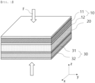
- FIG. 1 is a schematic view of a conventional all-solid-state battery.
- the conventional all-solid-state battery includes a positive electrode 10 including a positive electrode current collector 11 and a positive electrode active material layer 12 formed on at least one surface thereof by coating, a solid electrolyte layer 20, and a negative electrode 30 including a negative electrode current collector 31 and a negative electrode active material layer 32 formed on at least one surface thereof by coating.
- the negative electrode may be used as a lithium plating and stripping mechanism through a current collector alone or using lithium metal without a separate negative electrode active material layer 32, unlike FIG. 1 .
- pressurization force F is applied to the battery from above and below in order to reduce interfacial resistance between the positive electrode 10 and the solid electrolyte layer 20 and between the solid electrolyte layer 20 and the negative electrode 30.
- the all-solid-state battery is initially charged and discharged while being pressurized, lithium is intercalated into the negative electrode active material, whereby the active material is expanded or the lithium is plated to the negative electrode 30, and therefore the thickness (z-axis) of the battery is increased and pressure applied to the interior of the battery is also increased.
- the pressure applied to the interior of the all-solid-state battery is increased, the position and shape of the positive electrode 10, the solid electrolyte layer 20, and the negative electrode 30 in the all-solid-state battery are changed. Also, in the case in which the lithium is not uniformly plated on the negative electrode 30, the pressurization force F is not uniformly applied, whereby jigs that pressurize the all-solid-state battery from outside may be damaged.
- the lithium metal used in the all-solid-state battery is soft, whereby the capacity and performance of a unit cells are changed depending on the degree of pressurization or over time.
- the pressurization force F is increased, contact between the solid electrolyte and the lithium metal is increased, whereby the lithium metal is introduced into the solid electrolyte layer through cracks formed therein, and therefore a possibility of short circuit occurring in the battery is increased.
- This problem may be equally applied to a conventional lithium secondary battery including a separator, which replaces the solid electrolyte.
- Patent Document 1 a stack including a positive electrode, a solid electrolyte layer, and a negative electrode is pressurized in order to improve conductivity, electron conductivity, and lithium ion conductivity.
- this patent document does not disclose reducing stress applied to an all-solid-state battery in order to prevent a cell short circuit phenomenon of a unit cell.
- Patent Document 2 a stack including a positive electrode, a solid electrolyte layer, and a negative electrode is pressurized in order to reduce interfacial resistance.
- this patent document does not disclose reducing stress applied to an all-solid-state battery in order to improve safety of a unit cell.
- Patent Document 1 Japanese Patent Application Publication No. 2018-181451 (2018.11.15 )
- Patent Document 2 Japanese Patent Application Publication No. 2019-200890 (2019.11.21 )
- the present invention has been made in view of the above problems, and it is an object of the present invention to provide a construction for uniformly applying pressure when pressurization is performed in order to form an interface of a lithium secondary battery or an all-solid-state battery. It is another object of the present invention to uniformly distribute or reduce stress in a lithium secondary battery or an all-solid-state battery.
- the present invention provides an electrode including a porous support and a conductive coating layer formed on at least one surface of the porous support.
- the electrode may be a negative electrode or a positive electrode, preferably a negative electrode.
- the electrode is applicable to both an all-solid-state battery and a lithium secondary battery.
- the porous support may include an elastic material. When pressurized, the porous support may be deformed to reduce pressure.
- pressure may be pressure in the porous support, or pressure outside the porous support may be reduced as the result of deformation of the porous support.
- the porous support which is a porous support having a plurality of pores, may be a porous polymer film or porous polymer non-woven fabric that has a plurality of pores and is elastically deformable.
- the porous support may include a sheet or non-woven fabric made of a polyolefin-based porous substrate or at least one selected from the group consisting of glass fiber and polyethylene.
- the porous support may further include at least one of ceramics, metal, or a metal alloy in a polymer having a porous structure.
- the porous support may be uniaxially or biaxially oriented.
- the porous support has a porosity of 10% to 90%, preferably 35% to 85%.
- porosity is a ratio of empty portions to the total volume.
- the porous support may include pores each having a diameter of 0.01 um to 10 ⁇ m.
- the porous support may have a pressurization-based elastic strain of 30% or less.
- the pressurization-based elastic strain may be calculated as (thickness before pressurization - thickness under 20 MPa pressurization)/thickness before pressurization x 100%.
- the porous support may have a pressurization-based thickness retention rate of 70% or more.
- the pressurization-based thickness retention rate may be calculated as (thickness after pressurization/thickness before pressurization) x 100%.
- the thickness after pressurization may be a thickness under 20 MPa pressurization.
- the porous support may have a thickness before pressurization of 5 um to 300 ⁇ m.
- the thickness of the porous support may be decreased in a pressurization direction, and the area of the porous support may be increased in a direction perpendicular to the pressurization direction.
- the electrode may be a negative electrode, the negative electrode may include the conductive coating layer and a negative electrode active material layer, and the negative electrode active material layer may be formed on the conductive coating layer by plating through a charging process of a battery and may be stripped from the surface of the conductive coating layer through a discharging process of the battery.
- the conductive coating layer may be a conductive material layer, preferably a metal or metal oxide layer, formed on the surface of the porous support or the surface of each pore formed in the porous support by coating.
- the conductive coating layer may include a metal having electrical conductivity, specifically at least one metal powder and a metal oxide.
- the conductive coating layer may include a lithium affinity material, and non-limiting examples of the lithium affinity material may be one or more selected from the group consisting of metals, including Au, Ag, Fe, Mg, Al, Ti, Cr, Ni, Cu, Zn, In, Sn, Pt, Co, Mn, Li, Bi, and Si; and metal oxides, including CuO, ZnO, MnO, and CoO.
- the lithium affinity material may be one or more selected from the group consisting of metals, including Au, Ag, Fe, Mg, Al, Ti, Cr, Ni, Cu, Zn, In, Sn, Pt, Co, Mn, Li, Bi, and Si; and metal oxides, including CuO, ZnO, MnO, and CoO.
- the conductive coating layer may have a thickness of 100 nm to 5 ⁇ m.
- the present invention provides a lithium secondary battery including the electrode as a negative electrode.
- the present invention provides an all-solid-state battery including the electrode as a negative electrode.
- the all-solid-state battery may include a positive electrode, the negative electrode, and a solid electrolyte layer interposed between the positive electrode and the negative electrode.
- the conductive coating layer may be disposed on the surface opposite the solid electrolyte layer.
- the solid electrolyte layer may include a solid electrolyte, the solid electrolyte may have an ion conductivity of 10 -7 S/cm or more, and the solid electrolyte may include a polymer-based solid electrolyte, an oxide-based solid electrolyte, a sulfide-based solid electrolyte, or a mixture of two or more thereof.
- the present invention provides a method of manufacturing an all-solid-state battery, the method including (S1) forming a stack comprising a positive electrode, a solid electrolyte layer, and a negative electrode, (S2) pressurizing the stack, and (S3) charging the pressurized stack while pressurizing the stack, wherein at least one of the negative electrodes is a porous support having a conductive coating layer formed on one surface of the porous support.
- the present invention provides a method of manufacturing a lithium secondary battery including a separator, which replaces the solid electrolyte layer used in the method of manufacturing the all-solid-state battery.
- the step (S2) and the step (S3) may be performed in reverse order or may be performed simultaneously.
- the charging step (S3) may include providing a negative electrode active material layer on the conductive coating layer.
- the conductive coating layer may be formed by plating the conductive coating layer onto one surface of the porous support or laminating the conductive coating layer onto one surface of the porous support.
- the ratio of the thickness of the porous support before pressurization of the stack to the thickness of the porous support after pressurization of the stack is 1:0.4 to 1:0.9.
- pressurization pressure may be 20 MPa.
- lithium may be plated between the conductive coating layer used as the negative electrode and the solid electrolyte layer.
- the positive electrode may include a positive electrode active material layer including a metal oxide including lithium.
- the porous support may be deformed, whereby pressure applied to the interior of the porous support may be reduced.
- the positive electrode of the all-solid-state battery or the lithium secondary battery may include a porous support formed on at least one surface thereof.
- the present invention may be provided through various combinations of the technical solutions described above.
- a battery configured such that thickness expansion due to lithium plating is reduced using a negative electrode including a porous support, specifically a lithium secondary battery or an all-solid-state battery, and a method of manufacturing the same.
- the porous support may reduce internal stress generated due to lithium plating, whereby it is possible to inhibit occurrence of micro-short circuit. Consequently, it is possible to improve safety of the battery.
- lithium discharged from a positive electrode during a charging process may be plated onto a conductive coating layer, whereby the plated lithium may be used as a negative electrode active material layer without the provision of a separate negative electrode active material layer.
- the plated lithium may be stripped during a discharging process. In an initial state, therefore, the battery does not include a separate negative electrode active material layer.
- the expression "combination(s) thereof” included in a Markush expression means a mixture or combination of one or more selected from the group consisting of elements set forth in the Markush expression and means one or more selected from the group consisting of the elements.
- the present invention relates to an electrode including a porous support and a conductive coating layer formed on at least one surface of the porous support, preferably a negative electrode, and a lithium secondary battery or an all-solid-state battery including the electrode.
- a negative electrode will be described as including a porous support and a conductive coating layer formed on at least one surface of the porous support for the sake of convenience, which, however, may be applied to a positive electrode, and a lithium secondary battery or an all-solid-state battery according to the present invention may use at least one of a positive electrode and a negative electrode having a structure according to the present invention.
- a negative electrode used in an all-solid-state battery may use a graphite-based material as a negative electrode active material.
- the graphite-based material is used as the negative electrode active material, high interface resistance with a solid electrolyte layer occurs.
- Si or Sn is used as the negative electrode active material
- the inventors of the present application provide a new-concept negative electrode for all-solid-state batteries.
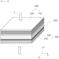
- an all-solid-state battery includes a porous support and a conductive coating layer as a negative electrode current collector in a negative electrode. This is shown in FIG. 2 .
- a negative electrode 300 according to an embodiment of the present invention includes a porous support 310; and a conductive coating layer 320 located on the porous support.
- a problem in that the negative electrode is expanded due to lithium plating may be solved by the porous support.
- the volume of the original porous support is reduced as the result of lithium plating, whereby the porous support may function as a thin film current collector.
- energy density may be increased. Since stress generated due to lithium plating is released by the porous support, it is possible to inhibit physical change of lithium in the state in which the battery is not charged/discharged. It is possible to solve a problem in that lithium plated during charging/discharging of the battery grows, thus damaging the solid electrolyte layer. As a result, lifespan characteristics of the battery are improved.
- the negative electrode according to the embodiment of the present invention may use a porous support and a conductive coating layer formed on the porous support as a negative electrode current collector.
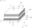
- the negative electrode may include the negative electrode current collector and a negative electrode active material layer. This is shown in FIG. 3 .
- a negative electrode 300 according to an embodiment of the present invention includes a negative electrode current collector 310 and 320 and a negative electrode active material layer 330.
- the negative electrode active material layer is formed on the negative electrode current collector by plating through a charging process of a battery and is stripped from the surface of the negative electrode current collector through a discharging process of the battery.
- plated lithium generated during charging/discharging of the battery may be used as the negative electrode active material layer.
- the porous support may be used without limitations as long as the porous support has a plurality of pores and is elastically deformable while not disturbing the operation of the battery.
- the porous support may be made of a material that has a plurality of pores and is elastically deformable, such as a porous polymer film substrate, a porous polymer non-woven fabric substrate, mesh, or porous foam.
- the porous support may be made of a material configured such that the thicknesses of the material before and after pressurization are similar to each other while the material is greatly deformable when being pressurized, i.e. a material having elastic force.
- the material having elastic force may be at least one selected from the group consisting of high-density polyethylene, low-density polyethylene, linear low-density polyethylene, ultrahigh molecular weight polyethylene, polypropylene, polyethylene terephthalate, polybutylene terephthalate, polyester, polyacetal, polyamide, polycarbonate, polyimide, polyetheretherketone, polyethersulfone, polyphenylene oxide, polyphenylene sulfide, polyethylene naphthalene, and a mixture thereof.
- the porous polymer non-woven fabric substrate may be polyolefin, polyethylene terephthalate, polybutylene terephthalate, polyester, polyacetal, polyamide, polycarbonate, polyimide, polyetheretherketone, polyethersulfone, polyphenylene oxide, polyphenylene sulfide, or polyethylene naphthalene, which may be used alone or as a polymer mixture thereof.
- the polymer non-woven fabric substrate does not correspond to a porous substrate applied to the present invention.
- the porous support is made of an elastic material, the porous support may be deformed by pressure applied to the battery in order to disperse or reduce stress applied to the negative electrode.
- the porous support may include a sheet or non-woven fabric manufactured using an olefin-based porous substrate including chemical resistant and hydrophobic polypropylene or at least one selected from the group consisting of glass fiber and polyethylene.
- the olefin-based porous substrate used for the porous support which is a porous polyolefin substrate used for the separator of the secondary battery, has no inorganic coating layers formed on opposite surfaces thereof.
- the olefin-based porous substrate may be polyethylene or polypropylene.
- the porous support may have a non-woven fabric structure or a uniaxially or biaxially oriented porous structure.
- the porous support may include a pore having a diameter of 0.01 um to 10 um.
- porosity of the porous support may range from 10% to 90%, preferably from 35% to 85%.
- porosity of the porous support may be 35% or more, 40% or more, or 45% or more, and may be 85% or less, 80% or less, or 75% or less.
- the porous support may have appropriate elastic force within the above numerical range in order to release stress generated at the time of charging and discharging.
- the porous support has the minimum thickness strain capable of absorbing stress within the above numerical range and elastic force restorable after lithium plating and stripping within the range.
- porosity is a ratio of empty portions to the total volume.
- stress generated in the battery may be reduced in a manner in which the size or number of the pores is reduced even though the structure of the porous support is not greatly changed.
- the porous support according to the present invention may have a thickness of 5 um to 300 um, preferably 5 um to 100 ⁇ m, before pressurization in order to efficiently reduce stress generated in the battery. More specifically, the thickness of the porous polymer support may be 5 um or more, 10 um or more, or 20 um or more, and may be 100 um or less, 80 um or less, or 50 um or less. The above numerical range is advantageous in minimizing reduction in energy density and achieving a stress relief effect. If the thickness of the porous support is too small, stress in the battery may not be reduced, which is undesirable. If the thickness of the porous support is too large, the performance of the battery may be reduced, compared to the size of the battery, which is also undesirable.
- the size of the pores may be reduced or the number of the pores may be reduced, compared to the case in which a material that has merely elastic force is used, whereby change in position or form of the porous support may be reduced, and therefore it is possible to more effectively reduce stress in the battery.
- the pores may be easily restored to the original state thereof.
- the porous support is made of a material similar or identical to the separator of the lithium secondary battery or the solid electrolyte layer of the all-solid-state battery, it is possible to stack unit cells without a separate separator or insulating material being interposed between the unit cells.
- At least one of ceramics, metal, or a metal alloy may be further included in the polymer having the porous structure of the porous support. Ceramics, metal, or a metal alloy may be included in the porous support such that the porous support performs the function of the negative electrode together with a negative electrode current collector layer. In this case, a separate conductive coating layer according to the present invention may not be necessary. In this case, however, a separate separator or insulating material may be necessary when the unit cells are stacked.
- lithium ions discharged from the positive electrode may be plated on the negative electrode current collector.
- the negative electrode current collector is porous.
- the porous support is elastically deformable, and the thickness of the porous support may be reduced when the plated lithium forms a negative electrode active material layer between the conductive coating layer and the solid electrolyte layer. That is, the porous support may be compressed. Consequently, it is possible to reduce stress generated due to the plated lithium.
- the thickness of the porous support may be controlled to dampen stress generated depending on some or the entirety of the amount of the plated lithium.
- the lithium may be plated on the negative electrode current collector to a thickness of 5 um.
- the porous support it is preferable for the porous support to have a porosity of 50% and a thickness of 10 um.
- the loading amount of the positive electrode active material layer is increased and thus the amount of lithium plated on the negative electrode current collector is increased, it is possible to reduce the generated stress while the thickness of the porous support is reduced.
- the pressurization-based elastic strain of the porous support may be 30% or less.
- the pressurization-based elastic strain may be calculated as (thickness before pressurization - thickness under 20 MPa pressurization)/thickness before pressurization x 100%.
- the pressurization-based thickness retention rate of the porous support may be 70% or more.
- the pressurization-based thickness retention rate may be calculated as (thickness after pressurization/thickness before pressurization) x 100%.
- the thickness after pressurization may be a thickness under 20 MPa pressurization.
- the porous support has elastic force, as described above. Even though lithium is plated between the negative electrode and the solid electrolyte layer during charging of the battery, therefore, the volume of the substrate may be reduced in proportion to the volume at which the lithium is plated. Consequently, it is possible to reduce expansion of the negative electrode due to lithium plating.
- the porous support When the porous support is deformed, the porous support may be deformed in a thickness direction, the area of the porous support may be increased, or the porous support may be deformed in the thickness direction while the area of the porous support may be increased.
- a micro-scale uneven pattern may be formed at the surface of the porous support in order to increase force of binding with the separator or the solid electrolyte layer.
- the conductive coating layer is a metal layer formed on the surface of the porous support or the surface of each pore formed in the porous support by coating.
- the porous support performs the function of a current collector due to the conductive coating layer. Forming a layer only on the surface of the porous support by coating is good in the aspect of driving of the battery. During coating with metal, however, some of the metal may be formed on the surfaces of the pores formed in the porous support. As another example, a conductive material of the conductive coating layer may be uniformly disposed in the porous support.
- the conductive coating layer may be formed on the porous support by coating.
- the coating method is not particularly restricted. For example, immersing, spin coating, dip coating, spray coating, doctor blade coating, solution casting, drop coating, physical vapor deposition (PVD), or chemical vapor deposition (CVD) may be used.
- PVD physical vapor deposition
- CVD chemical vapor deposition
- the conductive coating layer has electrical conductivity.
- the conductive coating layer includes a metal having electrical conductivity.
- the electrical conductivity is the degree of electrical conduction. Specifically, the degree at which a material or a solution is capable of carrying electric charge, which is a physical quantity, may be calculated as the reciprocal of resistance.
- the conductive coating layer may include a metal having electrical conductivity, specifically at least one of metal powder and a metal oxide.
- the conductive coating layer may include a lithium affinity material.
- the lithium affinity material may be one or more selected from the group consisting of metals, including Au, Ag, Fe, Mg, Al, Ti, Cr, Ni, Cu, Zn, In, Sn, Pt, Co, Mn, Li, Bi, and Si, and metal oxides, including CuO, ZnO, MnO, and CoO.
- the thickness of the conductive coating layer may range from 100 nm to 5 um. More specifically, the thickness of the conductive coating layer may be 100 nm or more, 500 nm or more, or 1 um, and may be 5 um or less, 3 um or less, or 2 um or less. The above numerical range is advantageous in minimizing reduction in energy density.
- the solid electrolyte layer includes a solid electrolyte.
- the solid electrolyte has an ion conductivity of 10 -7 S/cm or more, preferably 10 -5 S/cm or more, and may include a polymer-based solid electrolyte, an oxide-based solid electrolyte, a sulfide-based solid electrolyte, or a mixture of two or more thereof.
- the solid electrolyte serves to transfer lithium ions in the electrode. Consequently, the solid electrolyte may be a material that has high ion conductivity, for example an ion conductivity of 10 -5 S/cm or more or 10 -4 S/cm.
- the polymer-based solid electrolyte may include a solid polymer electrolyte and a lithium salt.
- the solid polymer electrolyte may be formed by adding a lithium salt to a polymer containing a hetero element, such as oxygen, nitrogen, or sulfur, such that ions of dissociated salt are movable in the polymer.
- a hetero element such as oxygen, nitrogen, or sulfur
- the polymer-based solid electrolyte may include a solid polymer electrolyte formed by adding a polymer resin to a solvated lithium salt.
- the polymer resin may include a polyether-based polymer, a polycarbonate-based polymer, an acrylate-based polymer, a polysiloxane-based polymer, a phosphazene-based polymer, a polyethylene derivative, an alkylene oxide derivative such as polyethylene oxide, a phosphoric acid ester polymer, poly agitation lysine, polyester sulfide, polyvinyl alcohol, polyvinylidene fluoride, a polymer containing an ionic dissociation group, or a mixture of two or more thereof.
- the solid polymer electrolyte may include a branch-like copolymer formed by copolymerizing an amorphous polymer, such as polymethylmethacrylate (PMMA), polycarbonate, polysiloxane (pdms), and/or phosphazene, which is a comonomer, in the main chain of polyethylene oxide, which is a polymer resin, a comb-like polymer resin, and a crosslinking polymer resin, or may be a mixture of the polymers.
- PMMA polymethylmethacrylate
- pdms polysiloxane
- phosphazene which is a comonomer, in the main chain of polyethylene oxide
- polymer resin a polymer resin, a comb-like polymer resin, and a crosslinking polymer resin, or may be a mixture of the polymers.
- the lithium salt may include Li + as positive ions, and may include at least one selected from the group consisting of F - , Cl - , Br - , I - , NO 3 - , N(CN) 2 - , BF 4 - , ClO 4 - , AlO 4 - , AlCl 4 - , PF 6 - , SbF 6 - , AsF 6 - , F 2 C 2 O 4 - , BC 4 O 8 - , (CF 3 ) 2 PF 4 - , (CF 3 ) 3 PF 3 - , (CF 3 ) 4 PF 2 - , (CF 3 ) 5 PF - , (CF 3 ) 6 P - , CF 3 SO 3 - , C 4 F 9 SO 3 - , CF 3 CF 2 SO 3 - , (CF 3 SO 2 ) 2 N - , (F 2 SO 2 ) 2 N
- the sulfide-based solid electrolyte may include sulfur (S), and may include a metal belonging to Group 1 or 2 of the periodic table. Consequently, it is preferable for the sulfide-based solid electrolyte to have ion conductivity of the metal and to have electron insulation.
- the sulfide-based solid electrolyte may be a lithium ion conductive solid electrolyte including a compound represented by Formula 1 below.
- Formula 1 a compound represented by Formula 1 below.
- L indicates an element selected from among Li, Na, and K, wherein Li is preferable.
- M indicates an element selected from among B, Zn, Sn, Si, Cu, Ga, Sb, Al, and Ge. Thereamong, B, Sn, Si, Al, or Ge is preferable, and Sn, Al, or Ge is more preferable.
- A indicates I, Br, Cl, or F, wherein I or Br is preferable and I is more preferable.
- a1 to e1 indicate composition ratios of the respective elements, and a1:b1:c1:d1:e1 satisfies 1 to 12:0 to 1:1:2 to 12:0 to 5. For a1, 1 to 9 is preferable, and 1.5 to 4 is more preferable. For a1, 1 to 9 is preferable, and 1.5 to 4 is more preferable. For b1, 0 to 0.5 is preferable. For d1, 3 to 7 is preferable, and 3.25 to 4.5 is more preferable. For e1, 0 to 3 is preferable, and
- the sulfide-based solid electrolyte may include Li, X, and S, wherein X may include at least one selected from the group consisting of P, Ge, B, Si, Sn, As, Cl, F, and I.
- the oxide-based solid electrolyte may include oxygen (O), and may include a metal belonging to Group 1 or 2 of the periodic table. Consequently, it is preferable for the oxide-based solid electrolyte to have ion conductivity of the metal and to have electron insulation.
- the oxide-based solid electrolyte may include Li, A, and O, wherein A may include at least one selected from the group consisting of La, Zr, Ti, Al, P, and I.
- the average particle diameter of the sulfide-based or oxide-based solid electrolyte is preferably 0.01 um or more, more preferably 0.1 um or more, although not particularly restricted.
- the upper limit of the average particle diameter of the sulfide-based or oxide-based solid electrolyte is preferably 100 um or less, more preferably 50 um or less.
- the average particle diameter of the sulfide-based or sulfide-based solid electrolyte may be measured using the following method.
- a dispersion solution in which 1 mass% of the solid electrolyte particles are dispersed in a 20 ml sample bottle using water (heptane for a material that is unstable in water) is prepared.
- an ultrasonic wave of 1 kHz is applied to the dispersion solution for 10 minutes, and a test is immediately performed.
- data reading is performed 50 times through a quartz cell for measurement at a temperature of 25°C using a laser diffraction/scattering type particle size distribution measurement apparatus LA-920 (HORIBA Company) to obtain a volume average particle diameter as an average particle diameter.
- LA-920 laser diffraction/scattering type particle size distribution measurement apparatus
- a sulfide, nitride, or halide of Li such as Li 6.25 La 3 Zr 2 A 10 ⁇ 25 O 12 , Li 3 PO 4 , Li 3 +xPO 4 -xN x (LiPON), Li 3 N, LiI, Li 5 NI 2 , Li 3 N-LiI-LiOH, LiSiO 4 , LiSiO 4 -LiI-LiOH, Li 2 SiS 3 , Li 4 SiO 4 , or Li 4 SiO 4 -LiI-LiOH, may be used as the oxide-based solid electrolyte.
- the sulfide is not particularly restricted, and all known sulfide-based materials used in a lithium battery field may be available. Products on the market may be used as the sulfide-based materials, or amorphous sulfide-based materials may be crystallized to manufacture the sulfide-based materials. For example, a crystalline sulfide-based solid electrolyte, an amorphous sulfide-based solid electrolyte, or a mixture thereof may be used as the sulfide-based solid electrolyte.
- a sulfur-halogen compound, a sulfur-germanium compound, and a sulfur-silicon compound as examples of available composite compounds.
- a sulfide such as SiS 2 , GeS 2 , or B 2 S 3 , may be included, and Li 3 PO 4 , halogen, or a halogen compound may be added.
- a sulfide-based electrolyte capable of implementing a lithium ion conductivity of 10 -4 S/cm or more is used.
- Li 6 PS 5 Cl LPSCl
- Thio-LISICON Li 3.25 Ge 0.25 P 0.75 S 4
- Li 2 S-P 2 S 5 -LiCl Li 2 S-SiS 2 , LiI-Li 2 S-SiS 2 , LiI-Li 2 S-P 2 S 5 , LiI-Li 2 S-P 2 O 5 , LiI-Li 3 PO 4 -P 2 S 5 , Li 2 S-P 2 S 5 , Li 3 PS 4 , Li 7 P 3 S 11 , LiI-Li 2 S-B 2 S 3 , Li 3 PO 4 -Li 2 S-Si 2 S, Li 3 PO 4 -Li 2 S-SiS 2 , LiPO 4 -Li 2 S-SiS, Li 10 GeP 2 S 12 , Li 9.54 Si 1.74 P 1.44 S 11.7 Cl 0.3 , and Li 7 P 3 S 11 are included.
- the positive electrode applied to the present invention is not particularly restricted, and an electrode active material layer may be bound to an electrode current collector using an ordinary method known in the art to which the present invention pertains to manufacture the positive electrode.
- the positive electrode may include a current collector and a positive electrode active material layer formed on at least one surface of the current collector, and the positive electrode active material layer may include a positive electrode active material, a binder, and a conductive agent.
- the positive electrode may include a solid electrolyte. The solid electrolyte may be the same as above.
- the positive electrode current collector is manufactured so as to have a thickness of 3 um to 500 um.
- the positive electrode current collector is not particularly restricted as long as the positive electrode current collector exhibits high conductivity while the positive electrode current collector does not induce any chemical change in a battery to which the positive electrode current collector is applied.
- the positive electrode current collector may be made of stainless steel, aluminum, nickel, titanium, or sintered carbon.
- the positive electrode current collector may be made of aluminum or stainless steel, the surface of which is treated with carbon, nickel, titanium, or silver.
- the positive electrode current collector may have a micro-scale uneven pattern formed on the surface thereof so as to increase the force of adhesion to the positive electrode active material.
- the positive electrode current collector may be configured in any of various forms, such as a film, a sheet, a foil, a net, a porous body, a foam body, or a non-woven fabric body.
- the positive electrode active material is not particularly restricted as long as the positive electrode active material can be used for a positive electrode of an electrochemical device.
- the positive electrode active material may include any one selected from the group consisting of LiCoO 2 , LiNiO 2 , LiMn 2 O 4 , LiCoPO 4 , LiFePO 4 , LiNiMnCoO 2 , and LiNi 1-x-y-z Co x M1 y M2 z O 2 (each of M1 and M2 is any distinct one selected from the group consisting of Al, Ni, Co, Fe, Mn, V, Cr, Ti, W, Ta, Mg, and Mo, and x, y, and z are atomic fractions of distinct oxide composition elements, wherein 0 ⁇ x ⁇ 0.5, 0 ⁇ y ⁇ 0.5, 0 ⁇ z ⁇ 0.5, and x+y+z ⁇ 1) or a mixture of two or more thereof.
- the solid electrolyte included in the positive electrode may be a polymer solid electrolyte, an oxide-based solid electrolyte, or a sulfide-based solid electrolyte.
- the positive electrode active material layer may further include a lithium salt.
- the lithium salt may include Li + as positive ions, and may include at least one selected from the group consisting of F - , Cl - , Br - , I - , NO 3 - , N(CN) 2 - , BF 4 - , ClO 4 - , AlO 4 - , AlCl 4 - , PF 6 - , SbF6 - , AsF 6 - , F 2 C 2 O 4 - , BC 4 O 8 - , (CF 3 ) 2 PF 4 - , (CF 3 ) 3 PF 3 - , (CF 3 ) 4 PF 2 - , (CF 3 ) 5 PF - , (CF 3 ) 6 P - , CF 3 SO 3 - , C 4 F 9 SO 3 - , CF 3 CF 2 SO 3 - , (CF 3 SO 2 ) 2 N - , (F 2 SO 2 ) 2 N
- the conductive agent is generally added so that the conductive agent accounts for 0.1 to 30 weight% based on the total weight of the mixture including the positive electrode active material.
- the conductive agent is not particularly restricted as long as the conductive agent exhibits high conductivity without inducing any chemical change in a battery to which the conductive agent is applied.
- graphite such as natural graphite or artificial graphite
- carbon black such as carbon black, acetylene black, Ketjen black, channel black, furnace black, lamp black, or thermal black
- conductive fiber such as carbon fiber or metallic fiber
- metallic powder such as carbon fluoride powder, aluminum powder, or nickel powder
- conductive whisker such as zinc oxide or potassium titanate
- a conductive metal oxide such as titanium oxide
- a conductive material such as a polyphenylene derivative
- the binder which is included in the positive electrode, is a component assisting in binding between the active material and the conductive agent and in binding with the current collector.
- the binder is generally added in an amount of 0.1 to 30 weight% based on the total weight of the mixture including the positive electrode active material.
- binder there may be used polyvinylidene fluoride, polyvinyl alcohol, carboxymethylcellulose (CMC), starch, hydroxypropylcellulose, regenerated cellulose, polyvinyl pyrrolidone, tetrafluoroethylene, polyethylene, polypropylene, ethylene-propylene-diene terpolymer (EPDM), sulfonated EPDM, styrene butadiene rubber, fluoro rubber, and various copolymers.
- CMC carboxymethylcellulose
- EPDM ethylene-propylene-diene terpolymer
- EPDM ethylene-propylene-diene terpolymer
- EPDM ethylene-propylene-diene terpolymer
- sulfonated EPDM styrene butadiene rubber
- fluoro rubber fluoro rubber
- the present invention provides an all-solid-state battery or a lithium secondary battery including the above electrode as a negative electrode.
- the present invention provides an all-solid-state battery including the above electrode as a negative electrode.
- the all-solid-state battery may be an all-solid-state battery including a positive electrode, the negative electrode, and a solid electrolyte layer interposed between the positive electrode and the negative electrode.
- the conductive coating layer may be disposed on the surface opposite the solid electrolyte layer.
- the present invention relates to a method of manufacturing an all-solid-state battery.
- the present invention provides a method of manufacturing an all-solid-state battery including (S1) a step of forming a stack including a positive electrode, a solid electrolyte layer, and a negative electrode, (S2) a step of pressurizing the stack, and (S3) a step of charging the pressurized stack while pressurizing the stack, wherein at least one of the negative electrodes is a porous support having a conductive coating layer formed on one surface of the porous support.
- the present invention provides a method of manufacturing a lithium secondary battery including a separator, which replaces the solid electrolyte layer used in the method of manufacturing the all-solid-state battery.
- Step (S2) and step (S3) may be performed in reverse order or may be simultaneously performed.
- Charging of step (S3) may include a step of providing a negative electrode active material layer on the conductive coating layer.
- the conductive coating layer may be formed by plating the conductive coating layer onto one surface of the porous support or laminating the conductive coating layer onto one surface of the porous support.
- the ratio of the thickness of the porous support before pressurization of the stack to the thickness of the porous support after pressurization of the stack may be 1:0.4 to 1:0.9.
- pressurization pressure may be 20 MPa.
- lithium may be plated between the conductive coating layer used as the negative electrode and the solid electrolyte layer.
- the positive electrode may include a positive electrode active material layer including a metal oxide including lithium.
- step (S2) and step (S3) the porous support may be deformed, whereby pressure applied to the interior of the porous support may be reduced.
- Step (S1) may include the following sub-steps:
- the conductive coating layer may be plated onto one surface of the porous support, or the conductive coating layer may be laminated onto one surface of the porous support, whereby the conductive coating layer may be disposed on one surface of the porous support.
- the ratio of the thickness of the porous support before pressurization of the stack to the thickness of the porous support after pressurization of the stack may be 1:0.4 to 1:0.9.
- pressurization pressure may be 20 MPa.
- lithium may be plated between the negative electrode current collector and the solid electrolyte layer.
- the plated lithium may serve as a negative electrode active material layer.
- stress generated due to plating of the lithium may be reduced as the result of compression of the porous support.
- Step (S1-1) and step (S1-3) are not particularly restricted as long as these steps are performed using a method commonly used in the art to which the present invention pertains.
- step (S3) Charging of step (S3) is not particularly restricted as long as charging is performed using a method commonly used in the art to which the present invention pertains.
- step (S3) lithium discharged from the positive electrode during the charging process may be plated onto the negative electrode current collector, whereby the plated lithium may be used as a negative electrode active material layer.
- step (S2) and/or step (S3) the porous support is deformed to reduce pressure F applied from the outside, and the pressure F is uniformly distributed, whereby pressure applied to the entirety of the battery is reduced.
- the position of the positive electrode, the separator/solid electrolyte layer, and the negative electrode is not changed, and when they are pressurized, uniform pressure is applied thereto. Ultimately, therefore, short circuit does not occur in the battery, whereby safety of the battery is improved.
- the porous support is deformed such that the length of the porous support is decreased in a pressurization direction and is increased in a direction perpendicular to the pressurization direction, whereby pressure applied to the entirety of the battery is reduced.
- FIG. 4 is a schematic view of an all-solid-state battery according to an embodiment of the present invention
- FIG. 5 is a schematic view of the all-solid-state battery according to the embodiment of the present invention after charging and pressurization.
- the all-solid-state battery according to the present invention is constituted by a positive electrode 100 including a positive electrode current collector 110 and a positive electrode active material layer 120 formed on at least one surface thereof by coating, a separator/solid electrolyte layer 200, and a negative electrode 300 including a porous support 310 and a conductive coating layer 320 applied to at least one surface of the porous support 310.
- FIG. 5 is a schematic view of the all-solid-state battery according to the present invention after charging and pressurization.
- lithium is plated to form a lithium layer 330.
- the lithium layer 330 is charged under constant current/constant voltage (CC/CV) conditions.
- pressure F applied to the entirety of the all-solid-state battery may be changed depending on the amount of lithium formed in the battery and charging and discharging speed and time.
- the lithium layer 330 corresponds to a negative electrode active material layer.
- the size or number of the pores in the porous support 310, to which uniform force has been applied due to the pressure F, is reduced, whereby stress generated by the pressure F is released.
- the length of the porous support 310 is increased by the pressure F in directions perpendicular to the direction in which the pressure F is applied, i.e. width (f1, x) and depth (f2, y) directions of the porous support 310, and the thickness (f3, z) of the porous support 310 in the pressurization direction is decreased, whereby the pressure F applied to the lithium secondary battery is reduced, and therefore force applied to the lithium layer 330 and the entirety of the lithium secondary battery is reduced.
- Deformation in the width, depth, and thickness directions may occur, as shown in FIG. 5 , or three kinds of deformation, such as deformation in the width and depth directions, deformation in the thickness direction, and deformation in the width, depth, and thickness directions, may occur.
- the porous support 310 may be provided on one surface of the positive electrode 100. Since the porous support 310 has the same shape as one used in the negative electrode 300 according to the present invention, the porous support may be provided on the positive electrode 100 instead of the negative electrode 300, or the porous support may be provided on the positive electrode 100 while the negative electrode 300 is used.
- FIGs. 4 and 5 according to the present invention may be equally applied to a lithium secondary battery in the case in which the solid electrolyte layer is replaced by a separator.
- PE polyethylene
- Example 1-1 A polyethylene (hereinafter referred to as "PE") porous support having a porosity of 45%
- PE porous support having a porosity of 47% Example 1-2
- PET polyethylene terephthalate
- Example 1-3 polyethylene terephthalate
- Example 1-3 nickel foam having a porosity of 89%
- Comparative Example 1-1 were cut to 26.8 cm x 26.8 cm each, and pressurized at 5 MPa, 10 MPa, 15 MPa, and 20 MPa, respectively.
- Thicknesses of the porous supports according to Examples 1-1 to 1-3 and Comparative Example 1-1 before and after pressurization were measured. The results are shown in Table 1 below.
- the thickness after pressurization is a thickness measured after pressurization pressure is removed.
- Thickness before pressurization ⁇ m
- Thickness after 5 MPa pressurization ⁇ m
- Thickness after 10 MPa pressurization ⁇ m
- Thickness after 15 MPa pressurization ⁇ m
- Thickness after 20 MPa pressurization ⁇ m
- Example 1-1 9 9 9 8 7 Example 1-2 16 16 16 15 14
- FIG. 6 is a graph showing pressurization-based thickness retention rates of the porous supports according to Example 1-1, Example 1-2, Example 1-3, and Comparative Example 1-1. It can be seen that pressurization-based thickness retention rates of the porous supports according to all examples of the present invention are 70% or more even when the porous supports are pressurized at 20 MPa.
- the pressurization-based thickness retention rate may be calculated as (thickness after pressurization/thickness before pressurization) x 100%.
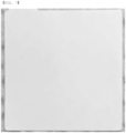
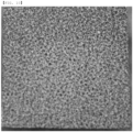
- FIGS. 7 and 8 are photographs of the porous support according to Example 1-1 before/after pressurization. It can be seen from FIGS. 7 and 8 that there is little difference in thickness and surface shape of the porous support according to Example 1-1 before and after pressurization.
- FIGS. 9 and 10 are photographs of the support according to Comparative Example 1-1 before/after pressurization. Referring to FIGS. 6 , 9 , and 10 , it can be seen that the thickness of the support according to Comparative Example 1-1 is reduced when pressure is applied thereto and that the surface of the support is smooth.
- the thickness retention rate of the support according to Comparative Example 1-1 at 20 MPa is less than 40%, and is 70% or less even at 5 MPa, which is relatively low.
- the supports according to Example 1-1, Example 1-2, and Example 1-3 have high thickness retention rates of 70% or more even at a high pressure of 20 MPa. Consequently, it can be seen that porosity of the support according to Comparative Example 1-1 is not maintained, whereby it is difficult to reduce stress generated as the result of plating of lithium.
- a PET release film (Example 1-4), a PE zipper bag (Example 1-5), and Parafilm (Comparative Example 1-2) were cut to 26.8 cm x 26.8 cm each, and were pressurized by applying weights of 0.5 ton and 6 ton.
- the thicknesses before pressurization, the thicknesses at the time of pressurization, the restored thicknesses after pressurization, and the areas after pressurization of the porous supports according to Example 1-4, Example 1-5, and Comparative Example 1-2 were measured. The results are shown in Table 2 below.
- the PET release film is obtained by thinly coating one surface or opposite surfaces of a PET film with a silicone release agent using a micro-gravure coating method and hardening the same, and may prevent separation and contamination of an adhesive material and may protect an adhesive layer.
- the PE zipper bag is a product manufactured using PE, among products used as normal zipper bags.
- the Parafilm is a semitransparent flexible film constituted by a mixture of wax and polyolefin, and is a registered trademark of Bemis Company, Inc. having the head office at Neenah, Wisconsin, USA.
- the PE zipper bag exhibits elastic properties similar to those of the PET release film, but elastic force of the Parafilm is reduced. As described above, it can be seen that the films exhibit very different physical properties even though polymers are used.
- Rs indicates a resistance value measured using equipment
- peal indicates a resistivity value calculated by applying a thickness
- pbulk indicates a resistivity value of a generally known material.
- the negative electrode current collector has a resistance value similar to the resistance value of a general nickel current collector.
- the thickness of a plated silver coating layer is 1 um, which is ultrathin, as in each of Examples 2-3 and 2-5, the silver coating layer exhibits electrical conductivity remarkably higher than the electrical conductivity of the stainless steel SUS304 current collector, which is commonly used in the art to which the present invention pertains.
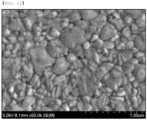
- FIG. 11 is an SEM photograph showing the surface of the negative electrode current collector according to Example 2-3. It can be seen that plated silver (Ag) particles are in dense contact with each other, whereby the silver particles have conductivity. In addition, it can be seen that, as in Table 2, a metal having electrical conductivity, such as silver (Ag) or gold (Au), can be used as a negative electrode current collector together with the porous support.
- the initial capacity was measured by performing charging and discharging at 60°C, and the efficiency obtained by dividing discharging capacity by charging capacity. The results are shown in Table 4 below.
- the negative electrode according to Example 2-3 was used as a negative electrode.
- a positive electrode was manufactured as follows. Specifically, NCM811 (LiNi 0.8 Co 0.1 Mn 0.1 O 2 ) as a positive electrode active material, Li 6 PS 5 Cl as an argyrodite solid electrolyte, carbon black as a conductive agent, and polytetrafluoroethylene (PTFE) as a binder polymer, were dispersed and stirred in anisole in the weight ratio of 77.5:19.5:1.5:1.5 to manufacture a positive electrode slurry. The positive electrode slurry was applied to an aluminum current collector having a thickness of 15 um using a doctor blade, and was dried under vacuum at 100°C for 12 hours.
- NCM811 LiNi 0.8 Co 0.1 Mn 0.1 O 2
- Li 6 PS 5 Cl as an argyrodite solid electrolyte
- carbon black as a conductive agent
- PTFE polytetrafluoroethylene
- the solid electrolyte was manufactured as follows. Specifically, Li 6 PS 5 Cl as an argyrodite solid electrolyte, and polytetrafluoroethylene (PTFE) as a binder polymer, were dispersed and stirred in anisole in a weight ratio of 95:5 to manufacture a slurry. The slurry was applied to an aluminum current collector having a thickness of 15 um using a doctor blade, and was dried under vacuum at 100°C for 12 hours.
- PTFE polytetrafluoroethylene
- the manufactured positive electrode, the manufactured solid electrolyte layer, and the negative electrode were sequentially stacked to manufacture an electrode assembly. Subsequently, the electrode assembly was put between jigs and a pressure of 5 MPa was applied to the electrode assembly.
- Example 3-1 This is identical to Example 3-1 except that a nickel foil having a thickness of 11 um and the porous support according to Example 1-1 are used instead of the negative electrode.
- Example 3-2 This is identical to Example 3-2 except that the porous support according to Example 1-3 is used instead of the porous support according to Example 1-1.
- Example 3-2 This is identical to Example 3-2 except that the electrode assembly is fastened to the jigs such that a force of 10 MPA is applied thereto instead of a pressure of 5 MPa.
- Example 3-1 This is identical to Example 3-1 except that a nickel foil having a thickness of 11 um and the porous support according to Example 1-4 are used instead of the negative electrode.
- Example 3-1 This is identical to Example 3-1 except that a nickel foil having a thickness of 11 um and the porous support according to Example 1-5 are used instead of the negative electrode.
- Example 3-2 This is identical to Example 3-2 except that the negative electrode does not have the porous support according to Example 1-1.
- PET non-woven fabric having a porosity of 47% is used instead of the porous support according to Example 1-1.
- the PET non-woven fabric having the porosity of 47% is non-woven fabric that has low elastic deformation and thus has very low thickness strain due to pressure.
- Table 4 shows experimental results of Examples 3-1 to 3-6 and Comparative Examples 3-1 and 3-2.
- Classification Charge (mAh/g), 60°C, 4.2V Discharge (mAh/g), 60°C, 3V Efficiency (%) Short circuit occurrence rate (%) Lifespan evaluation (0.1C, CC charging/discharging, 3.7 to 4.2V, 60°C)
- Example 3-1 228 201 88.2 0 83% @50 cycle maintained
- Example 3-2 223 205 91.9 0
- Example 3-4 the short circuit occurrence rate still has an excellent value even though pressurization pressure is increased to 10 MPa.
- the support according to Comparative Example 3-2 is made of non-woven fabric having excessively low thickness strain due to pressure, whereby fabrics in the non-woven fabric are not particularly contracted, and pressure is concentrated on junctions between the fabrics.
- lithium is nonuniformly plated onto the surface of the current collector at the time of charging and discharging, whereby the short circuit occurrence rate of the secondary battery is higher than in Examples.
- the present invention relates to an electrode including a porous support and a conductive coating layer formed on at least one surface of the porous support, and therefore the present invention has industrial applicability.
Landscapes
- Chemical & Material Sciences (AREA)
- Chemical Kinetics & Catalysis (AREA)
- Electrochemistry (AREA)
- General Chemical & Material Sciences (AREA)
- Engineering & Computer Science (AREA)
- Manufacturing & Machinery (AREA)
- Materials Engineering (AREA)
- Inorganic Chemistry (AREA)
- Composite Materials (AREA)
- General Physics & Mathematics (AREA)
- Condensed Matter Physics & Semiconductors (AREA)
- Physics & Mathematics (AREA)
- Secondary Cells (AREA)
- Battery Electrode And Active Subsutance (AREA)
- Cell Electrode Carriers And Collectors (AREA)
Applications Claiming Priority (4)
| Application Number | Priority Date | Filing Date | Title |
|---|---|---|---|
| KR1020200083066A KR102849244B1 (ko) | 2020-07-06 | 2020-07-06 | 도전재가 코팅된 고분자층으로 구성된 전극을 포함하는 전고체전지 및 이의 작동방법 |
| KR1020200089135A KR102870084B1 (ko) | 2020-07-17 | 2020-07-17 | 전고체 전지 및 이의 제조방법 |
| KR1020200090272A KR20220011408A (ko) | 2020-07-21 | 2020-07-21 | 다공성 지지체와 집전체 층을 포함하는 음극 및 이를 포함하는 리튬 이차전지 |
| PCT/KR2021/008534 WO2022010211A1 (ko) | 2020-07-06 | 2021-07-06 | 전고체전지 및 이의 제조방법 |
Publications (2)
| Publication Number | Publication Date |
|---|---|
| EP4177984A1 true EP4177984A1 (de) | 2023-05-10 |
| EP4177984A4 EP4177984A4 (de) | 2024-10-30 |
Family
ID=79553373
Family Applications (1)
| Application Number | Title | Priority Date | Filing Date |
|---|---|---|---|
| EP21838027.7A Pending EP4177984A4 (de) | 2020-07-06 | 2021-07-06 | Feststoffbatterie und herstellungsverfahren dafür |
Country Status (5)
| Country | Link |
|---|---|
| US (1) | US20230290956A1 (de) |
| EP (1) | EP4177984A4 (de) |
| JP (1) | JP7562208B2 (de) |
| CN (1) | CN115298851B (de) |
| WO (1) | WO2022010211A1 (de) |
Cited By (1)
| Publication number | Priority date | Publication date | Assignee | Title |
|---|---|---|---|---|
| WO2023222326A1 (de) * | 2022-05-20 | 2023-11-23 | Bayerische Motoren Werke Aktiengesellschaft | Lithiumbatterie umfassend eine lithiummetallanode mit einem porösen stromableiter |
Families Citing this family (1)
| Publication number | Priority date | Publication date | Assignee | Title |
|---|---|---|---|---|
| CN121601671A (zh) * | 2024-08-15 | 2026-03-03 | 宁德时代新能源科技股份有限公司 | 二次电池、负极集流体及其制备方法和用电装置 |
Family Cites Families (20)
| Publication number | Priority date | Publication date | Assignee | Title |
|---|---|---|---|---|
| JP2005243588A (ja) * | 2004-03-01 | 2005-09-08 | Japan Vilene Co Ltd | リチウム電池用集電材、その製造方法、及びリチウム電池 |
| KR100669338B1 (ko) * | 2005-07-18 | 2007-01-16 | 삼성에스디아이 주식회사 | 리튬 이차 전지용 음극 및 이를 포함하는 리튬 이차 전지 |
| JP2008016329A (ja) * | 2006-07-06 | 2008-01-24 | Sumitomo Electric Ind Ltd | リチウム二次電池用負極材 |
| JP2010009989A (ja) * | 2008-06-27 | 2010-01-14 | Sanyo Electric Co Ltd | 二次電池の充放電方法とバッテリ装置 |
| JP2015092433A (ja) * | 2012-02-24 | 2015-05-14 | 住友電気工業株式会社 | 全固体リチウム二次電池 |
| KR101592355B1 (ko) * | 2013-08-05 | 2016-02-11 | 주식회사 아모그린텍 | 플렉시블 집전체를 이용한 이차전지 및 플렉시블 집전체의 제조방법 |
| KR102056455B1 (ko) * | 2016-07-15 | 2019-12-16 | 주식회사 엘지화학 | 음극 및 이를 포함하는 이차 전지 |
| KR101990614B1 (ko) * | 2016-09-07 | 2019-06-18 | 주식회사 엘지화학 | 리튬 전극 및 이를 포함하는 리튬 이차 전지 |
| JP7050419B2 (ja) * | 2017-02-07 | 2022-04-08 | 三星電子株式会社 | 全固体型二次電池用負極及び全固体型二次電池 |
| JP6887088B2 (ja) | 2017-04-04 | 2021-06-16 | パナソニックIpマネジメント株式会社 | 積層型全固体電池およびその製造方法 |
| JP7050465B2 (ja) * | 2017-11-14 | 2022-04-08 | 三星電子株式会社 | 全固体二次電池用固体電解質、全固体二次電池、および固体電解質の製造方法 |
| JP6995579B2 (ja) * | 2017-11-17 | 2022-01-14 | 旭化成株式会社 | 二次電池用不織布集電体 |
| PL3671934T3 (pl) * | 2018-03-27 | 2022-05-09 | Lg Energy Solution Ltd. | Akumulator litowo-metalowy |
| JP7014043B2 (ja) | 2018-05-15 | 2022-02-01 | トヨタ自動車株式会社 | 電極層の製造方法 |
| JP7077766B2 (ja) * | 2018-05-18 | 2022-05-31 | トヨタ自動車株式会社 | 硫化物系固体電解質、当該硫化物系固体電解質の製造方法、及び、全固体電池の製造方法 |
| KR102538143B1 (ko) * | 2018-10-15 | 2023-05-26 | 주식회사 엘지에너지솔루션 | 전고체 전지 제조 방법 |
| KR102684234B1 (ko) * | 2018-11-07 | 2024-07-12 | 한국전기연구원 | 리튬금속 이차전지용 다공성 음극 구조체, 이의 제조방법 및 이를 포함하는 리튬금속 이차전지 |
| KR102227123B1 (ko) | 2018-12-31 | 2021-03-12 | (주) 안데르손 | 창호용 섬유재 광 촉매 에어필터 제조방법 및 그 제품 |
| KR20200090272A (ko) | 2019-01-10 | 2020-07-29 | 박중언 | 블럭식 모듈 조립 주택 |
| KR20200089135A (ko) | 2019-01-16 | 2020-07-24 | 주식회사 테라테크노스 | Si-SiOx 코어 쉘 구조의 나노와이어의 제조 방법 |
-
2021
- 2021-07-06 WO PCT/KR2021/008534 patent/WO2022010211A1/ko not_active Ceased
- 2021-07-06 JP JP2022566238A patent/JP7562208B2/ja active Active
- 2021-07-06 US US18/013,625 patent/US20230290956A1/en active Pending
- 2021-07-06 EP EP21838027.7A patent/EP4177984A4/de active Pending
- 2021-07-06 CN CN202180021314.8A patent/CN115298851B/zh active Active
Cited By (1)
| Publication number | Priority date | Publication date | Assignee | Title |
|---|---|---|---|---|
| WO2023222326A1 (de) * | 2022-05-20 | 2023-11-23 | Bayerische Motoren Werke Aktiengesellschaft | Lithiumbatterie umfassend eine lithiummetallanode mit einem porösen stromableiter |
Also Published As
| Publication number | Publication date |
|---|---|
| CN115298851A (zh) | 2022-11-04 |
| EP4177984A4 (de) | 2024-10-30 |
| JP2023524699A (ja) | 2023-06-13 |
| CN115298851B (zh) | 2025-08-29 |
| JP7562208B2 (ja) | 2024-10-07 |
| US20230290956A1 (en) | 2023-09-14 |
| WO2022010211A1 (ko) | 2022-01-13 |
Similar Documents
| Publication | Publication Date | Title |
|---|---|---|
| CN112534620B (zh) | 固体电解质膜、其制造方法以及包含其的全固态电池 | |
| KR102870084B1 (ko) | 전고체 전지 및 이의 제조방법 | |
| US20160308243A1 (en) | Electrochemical cell with solid and liquid electrolytes | |
| EP3843191A1 (de) | Festelektrolytmembran und feststoffbatterie damit | |
| EP4138198A1 (de) | Separator für sekundärbatterie mit haftschicht und verfahren zur herstellung des separators | |
| EP3809510A1 (de) | Festelektrolytmembran und feststoffbatterie damit | |
| EP4135089A1 (de) | Festkörperbatterie mit zwei arten von festelektrolytschichten | |
| EP3648197A1 (de) | Asymmetrisch strukturierter flammenhemmender separator für sekundärbatterie | |
| EP4274015A1 (de) | Separator für elektrochemische vorrichtung, elektrodenanordnung damit und sekundärbatterie | |
| EP3846255A1 (de) | Elektrode für eine festkörperbatterie und verfahren zur herstellung einer solchen elektrodenanordnung | |
| JP7694878B2 (ja) | 2種の固体電解質層を含む全固体電池及びその製造方法 | |
| WO2022212132A1 (en) | Electrode assemblies including current limiters, secondary batteries having such electrode assemblies, and methods of testing | |
| KR20220125366A (ko) | 분리막, 그 제조 방법 및 이와 관련된 이차 전지, 배터리 모듈, 배터리 팩 및 장치 | |
| EP4177984A1 (de) | Feststoffbatterie und herstellungsverfahren dafür | |
| EP4187671B1 (de) | Festkörperbatterie mit dünnschichtstromkollektor und dessen herstellungsverfahren | |
| EP4220750A1 (de) | Festkörperbatterieanode mit polymerschicht zur verhinderung von mikrokurzschluss und festkörperbatterie damit | |
| KR20220011408A (ko) | 다공성 지지체와 집전체 층을 포함하는 음극 및 이를 포함하는 리튬 이차전지 | |
| EP4080600B1 (de) | Elektrodenwalzvorrichtung und elektrodenwalzverfahren | |
| KR20250123748A (ko) | 다공성 지지층을 포함하는 바이폴라 전고체전지 | |
| KR102849244B1 (ko) | 도전재가 코팅된 고분자층으로 구성된 전극을 포함하는 전고체전지 및 이의 작동방법 | |
| CN116569379A (zh) | 包括比负极具有更宽面积的正极的全固态电池及其制造方法 | |
| EP4170775A1 (de) | Elektrodenanordnung mit separator mit darauf geformter leitfähiger schicht und batteriezelle damit | |
| KR20220061439A (ko) | 다공성 집전체를 포함하는 바이폴라 전고체전지 | |
| KR20220047106A (ko) | 미세 쇼트 방지를 위한 금속-고분자층을 포함하는 전고체전지용 음극 및 이를 포함하는 전고체전지 | |
| KR102948619B1 (ko) | 2종의 고체전해질층을 포함하는 전고체전지 및 이의 제조방법 |
Legal Events
| Date | Code | Title | Description |
|---|---|---|---|
| STAA | Information on the status of an ep patent application or granted ep patent |
Free format text: STATUS: THE INTERNATIONAL PUBLICATION HAS BEEN MADE |
|
| PUAI | Public reference made under article 153(3) epc to a published international application that has entered the european phase |
Free format text: ORIGINAL CODE: 0009012 |
|
| STAA | Information on the status of an ep patent application or granted ep patent |
Free format text: STATUS: REQUEST FOR EXAMINATION WAS MADE |
|
| 17P | Request for examination filed |
Effective date: 20220907 |
|
| AK | Designated contracting states |
Kind code of ref document: A1 Designated state(s): AL AT BE BG CH CY CZ DE DK EE ES FI FR GB GR HR HU IE IS IT LI LT LU LV MC MK MT NL NO PL PT RO RS SE SI SK SM TR |
|
| DAV | Request for validation of the european patent (deleted) | ||
| DAX | Request for extension of the european patent (deleted) | ||
| A4 | Supplementary search report drawn up and despatched |
Effective date: 20240927 |
|
| RIC1 | Information provided on ipc code assigned before grant |
Ipc: H01M 4/02 20060101ALI20240923BHEP Ipc: H01M 10/058 20100101ALI20240923BHEP Ipc: H01M 4/139 20100101ALI20240923BHEP Ipc: H01M 10/052 20100101ALI20240923BHEP Ipc: H01M 4/66 20060101ALI20240923BHEP Ipc: H01M 4/80 20060101ALI20240923BHEP Ipc: H01M 4/13 20100101AFI20240923BHEP |
|
| STAA | Information on the status of an ep patent application or granted ep patent |
Free format text: STATUS: EXAMINATION IS IN PROGRESS |
|
| 17Q | First examination report despatched |
Effective date: 20250626 |
|
| GRAP | Despatch of communication of intention to grant a patent |
Free format text: ORIGINAL CODE: EPIDOSNIGR1 |
|
| STAA | Information on the status of an ep patent application or granted ep patent |
Free format text: STATUS: GRANT OF PATENT IS INTENDED |
|
| INTG | Intention to grant announced |
Effective date: 20251218 |
|
| GRAS | Grant fee paid |
Free format text: ORIGINAL CODE: EPIDOSNIGR3 |
|
| GRAA | (expected) grant |
Free format text: ORIGINAL CODE: 0009210 |
|
| STAA | Information on the status of an ep patent application or granted ep patent |
Free format text: STATUS: THE PATENT HAS BEEN GRANTED |