EP4178065A1 - Rückspeisungssperre für transformatorgleichrichtereinheit (tru) - Google Patents
Rückspeisungssperre für transformatorgleichrichtereinheit (tru) Download PDFInfo
- Publication number
- EP4178065A1 EP4178065A1 EP22205160.9A EP22205160A EP4178065A1 EP 4178065 A1 EP4178065 A1 EP 4178065A1 EP 22205160 A EP22205160 A EP 22205160A EP 4178065 A1 EP4178065 A1 EP 4178065A1
- Authority
- EP
- European Patent Office
- Prior art keywords
- tru
- contactor
- bus
- backfeed
- power
- Prior art date
- Legal status (The legal status is an assumption and is not a legal conclusion. Google has not performed a legal analysis and makes no representation as to the accuracy of the status listed.)
- Pending
Links
Images

Classifications
-
- H—ELECTRICITY
- H02—GENERATION; CONVERSION OR DISTRIBUTION OF ELECTRIC POWER
- H02H—EMERGENCY PROTECTIVE CIRCUIT ARRANGEMENTS
- H02H7/00—Emergency protective circuit arrangements specially adapted for specific types of electric machines or apparatus or for sectionalised protection of cable or line systems, and effecting automatic switching in the event of an undesired change from normal working conditions
- H02H7/22—Emergency protective circuit arrangements specially adapted for specific types of electric machines or apparatus or for sectionalised protection of cable or line systems, and effecting automatic switching in the event of an undesired change from normal working conditions for distribution gear, e.g. bus-bar systems; for switching devices
-
- H—ELECTRICITY
- H02—GENERATION; CONVERSION OR DISTRIBUTION OF ELECTRIC POWER
- H02J—ELECTRIC POWER NETWORKS; CIRCUIT ARRANGEMENTS OR SYSTEMS FOR SUPPLYING OR DISTRIBUTING ELECTRIC POWER; SYSTEMS FOR STORING ELECTRIC ENERGY
- H02J4/00—Circuit arrangements for mains or distribution networks not specified as AC or DC; Circuit arrangements for mains or distribution networks combining AC and DC sections or sub-networks
- H02J4/20—Networks integrating separated AC and DC power sections
- H02J4/25—Networks integrating separated AC and DC power sections for transfer of electric power between AC and DC networks, e.g. for supplying the DC section within a load from an AC mains system
-
- H—ELECTRICITY
- H02—GENERATION; CONVERSION OR DISTRIBUTION OF ELECTRIC POWER
- H02H—EMERGENCY PROTECTIVE CIRCUIT ARRANGEMENTS
- H02H1/00—Details of emergency protective circuit arrangements
- H02H1/0007—Details of emergency protective circuit arrangements concerning the detecting means
-
- H—ELECTRICITY
- H02—GENERATION; CONVERSION OR DISTRIBUTION OF ELECTRIC POWER
- H02J—ELECTRIC POWER NETWORKS; CIRCUIT ARRANGEMENTS OR SYSTEMS FOR SUPPLYING OR DISTRIBUTING ELECTRIC POWER; SYSTEMS FOR STORING ELECTRIC ENERGY
- H02J4/00—Circuit arrangements for mains or distribution networks not specified as AC or DC; Circuit arrangements for mains or distribution networks combining AC and DC sections or sub-networks
-
- H—ELECTRICITY
- H02—GENERATION; CONVERSION OR DISTRIBUTION OF ELECTRIC POWER
- H02J—ELECTRIC POWER NETWORKS; CIRCUIT ARRANGEMENTS OR SYSTEMS FOR SUPPLYING OR DISTRIBUTING ELECTRIC POWER; SYSTEMS FOR STORING ELECTRIC ENERGY
- H02J2105/00—Networks for supplying or distributing electric power characterised by their spatial reach or by the load
- H02J2105/30—Networks for supplying or distributing electric power characterised by their spatial reach or by the load the load networks being external to vehicles, i.e. exchanging power with vehicles
- H02J2105/32—Networks for supplying or distributing electric power characterised by their spatial reach or by the load the load networks being external to vehicles, i.e. exchanging power with vehicles for aircrafts
Definitions
- the present disclosure relates to power supply and distribution, and more particularly to power supply and distribution such as in aircraft.
- a DC essential bus is able to be fed from a primary or normal power source such as a Transformer Rectifier Unit (TRU), potentially via a DC bus, and also fed from an alternate or emergency power source such as an essential TRU, which would be powered by a Ram Air Turbine (RAT) in an electrical emergency.
- TRU Transformer Rectifier Unit
- RAT Ram Air Turbine
- a TRU When a TRU is powered, primary system contactors are closed to power the respective DC essential bus. When the TRU is not powered, the same primary system contactors are opened, and an alternate system contactor is closed to power the DC essential bus from an alternate source.
- One of the primary system contactors is opened to prevent a DC bus load from overloading the alternate power source.
- some applications use an AC relay and interlock which would open the primary system contactors if TRU input power is lost to ensure proper load shed.
- the relay would open the first primary system contactor coil return, forcing the contactor open regardless of the contactor driver command.
- the second primary system contactor may be opened directly by this or via interlock with first primary system contactor.
- a system includes a transformer rectifier unit (TRU) including a backfeed sense module.
- TRU transformer rectifier unit
- a contactor is operatively connected to the TRU for selectively supplying DC power to a DC bus from the TRU with the contactor closed and isolating the DC bus from the TRU with the contactor opened.
- a contactor driver is operatively connected to receive a signal from the backfeed sense module and to control opening and closing of the contactor based on the signal. The contactor driver is configured to open the contactor upon receipt of the signal indicative of backfeed detected in the TRU.
- the TRU can include a first AC input line, a second AC input line, and a third AC input line all operatively connected to supply AC power from an AC bus to the TRU.
- the backfeed sense module can include one or more voltage, current, and/or power sensors operatively connected to the first AC input line, second AC input line, and third AC input line.
- the TRU can include a first DC output line and a second DC output line both operatively connected to supply DC power to a DC bus from the TRU.
- the backfeed sense module can be configured to produce and output the signal to the contactor driver with information indicative of backfeed detected in the TRU.
- the contactor driver can be configured to open the contactor upon receiving the signal with information indicative of backfeed in the TRU, in the event of no AC voltage, current and/or power sensed in the first, second, and third AC inputs.
- the contactor driver can be configured to open the contactor upon receiving the signal with information indicative of backfeed in the TRU, in the event of DC voltage, current and/or power sensed in the first and second DC inputs.
- the contactor driver can be operatively connected to control a coil of the contactor.
- the coil can be operatively connected to a return.
- a relay can be operatively connected to the backfeed sense module, and operatively connected between the contactor driver and the coil. It is also contemplated that the relay can be operatively connected between the coil and the return.
- the TRU can be a first TRU, wherein the contactor can be a first TRU contactor, and the system can include a first AC bus configured to supply power from a first AC power source, a second AC bus configured to supply power from a second AC power source, the first TRU connecting a first DC bus to the first AC bus through the first TRU contactor, and a second TRU connecting a second DC bus to the second AC bus through a second TRU contactor.
- a first DC essential bus can be connected to the first DC bus through a first essential contactor.
- a second DC essential bus can be connected to the second DC bus through a second essential contactor.
- An essential TRU can be connected to a third DC essential bus through an essential TRU contactor.
- a first essential tie contactor can selectively connect between the first DC essential bus and the third DC essential bus.
- a second ETC can selectively connect between the third DC essential bus and the second DC essential bus.
- An AC essential bus tie contactor (AETC) can selectively connect between an AC essential bus and the first and second AC busses.
- a ram air turbine (RAT) line contactor can connect between the AETC and the AC essential bus to selectively connect a RAT to the AC essential bus.
- a method of distributing power includes powering a DC bus with power from a transformer rectifier unit (TRU) thorough a contactor and detecting backfeed in the TRU.
- the method includes opening the contactor to disconnect the DC bus from the TRU in response to detecting the backfeed in the TRU.
- TRU transformer rectifier unit
- Detecting backfeed in the TRU can include monitoring one or more AC input lines to the TRU and monitoring one or more DC output lines from the TRU.
- the method can include determining there is backfeed in the TRU if there is voltage, current and/or power detected in the DC output lines but no voltage, current and/or power detected at the AC input lines. Determining there is backfeed in the TRU can include using one or more proxies for direct AC power sensor and/or for direct DC power sensing.
- Fig. 1 a partial view of an embodiment of a system in accordance with the disclosure is shown in Fig. 1 and is designated generally by reference character 100.
- Other embodiments of systems in accordance with the disclosure, or aspects thereof, are provided in Figs. 2-3 , as will be described.
- the systems and methods described herein can be used to provide power distribution such as in aircraft systems while avoiding backfeed in the transformer rectifier units (TRUs).
- TRUs transformer rectifier units
- the system 100 includes a first AC bus 102 configured to supply power from a first AC power source, e.g. generator 104.
- a second AC bus 106 is configured to supply power from a second AC power source, e.g. generator 108.
- a first transformer rectifier unit (TRU) 110 connects a first DC bus 112 to the first AC bus 102 through a first TRU contactor (TRUC) 114.
- TRUC TRU contactor
- a second TRU 116 connects a second DC bus 118 to the second AC bus 106 through a second TRUC 120.
- An AC essential bus tie contactor (AETC) 126 can selectively connect between an AC essential bus 128 and the first and second AC busses 102, 106.
- An AETC controller 130 is connected to switch the AETC 126 between a first state connecting the AC essential bus 128 to the first AC bus 102 and a second state connecting the AC essential bus 128 to the second AC bus 106.
- a first DC essential bus 132 is connected to the first DC bus 112 through a first essential contactor (EC) 134.
- a second DC essential bus 136 is connected to the second DC bus 118 through a second EC 138.
- An essential TRU 140 can be connected to a third DC essential bus 142 through an essential TRUC 144.
- a first essential tie contactor (ETC) 146 can selectively connect between the first DC essential bus 132 and the third DC essential bus 142.
- a second ETC 148 can selectively connect between the third DC essential bus 142 and the second DC essential bus 136.
- a ram air turbine (RAT) line contactor 168 connects between the AETC 126 and the AC essential bus 128 to selectively connect a RAT 124 to the AC essential bus 128.
- the AC and DC essential busses 128, 132, 136, and 142 can potentially be powered even if only one of the generators 104, 108 or RAT 124 is available, by controlling the various contactors.
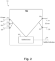
- the TRU 110 includes a backfeed sense module 202.
- the TRU 110 includes a first AC input line 204, a second AC input line 206, and a third AC input line 208 all operatively connected to supply AC power from an AC bus (e.g. AC bus 102 of Fig. 1 ) to the TRU 110.
- the backfeed sense module 202 includes a respective sensor 210, 212, 214, each operatively connected to the first AC input line 204, second AC input line 206, and third AC input line 208.
- the TRU includes a first DC output line 216 and a second DC output line 218 both operatively connected to supply DC power to a DC bus, e.g. DC bus 112 of Fig. 1 , from the TRU 110.
- the backfeed sense module 202 includes a respective sensor 220, 222, each operatively connected to the first DC output line 216 and the second DC output line 218.
- the sensor(s) 210, 212, 214, 220, 222 can be voltage sensors or any other suitable sensor type, e.g. current sensors, power sensors, or the like, for detecting voltage, current, and/or power in lines.
- the backfeed sense module 202 is configured to produce and output a signal, e.g. in signal line 224 (also shown in Fig. 2 ), to a contactor driver 226 with information indicative of backfeed detected in the TRU 110.
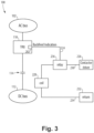
- the contactor driver 226 is operatively connected to receive the signal from the backfeed sense module 202 and to control opening and closing of the contactor 114 based on the signal.
- the contactor driver 226 is configured to open the contactor 114 upon receipt of the signal indicative of backfeed detected in the TRU 110.
- the contactor driver 226 is configured to open the contactor 114 in the event of no AC voltage, current and/or power sensed in the first, second, and third AC inputs 210, 212, 214 (shown in Fig. 2 ) but wherein there is DC voltage, current and/or power sensed in the first and second DC inputs 220, 222 (shown in Fig. 2 ).
- the contactor driver 226 is operatively connected to control a coil 228, e.g. a solenoid coil of the contactor 114, through line 230.
- the coil 228 is operatively connected to a return 232 by line 234.
- a relay 236 in line 230 is operatively connected between the contactor driver 226 and the coil 228 to relay the signal from the backfeed sense module 202 and to power or depower the coil 228. It is also contemplated that the relay 236 can instead be operatively connected in line 234 between the coil 228 and the return 232.
- the relay 236, contactor driver 226, and coil 228 form a relay interlock for the contactor 114.
- a method of distributing power includes powering a DC bus (e.g. DC bus 112, 118 of Fig. 1 ) with power from a TRU (e.g. TRU 110, 140, 116 of Fig. 1 ) thorough a contactor (e.g. contactor 114, 120, 144 of Fig. 1 ) and detecting backfeed in the TRU.
- the method includes opening the contactor to disconnect the DC bus from the TRU in response to detecting the backfeed in the TRU.
- Detecting backfeed in the TRU includes monitoring one or more AC input lines (e.g. AC input lines 204, 206, 208 of Fig. 2 ) to the TRU and monitoring one or more DC output lines (e.g. DC output lines 216, 218 of Fig.
- the method includes determining there is backfeed in the TRU if there is voltage, current and/or power detected in the DC output lines but no voltage, current and/or power detected at the AC input lines.
- the backfeed sense module 202 and/or contactor driver 226 can include machine readable instructions configured to carry out the methods disclosed herein, which can include analog, digital, and/or electronic circuit implemented machine readable instructions.
- All three TRUs can have backfeed sensing using direct AC input and/or direct DC input, or can use one or more proxies for direct AC or DC input such as using an engine's fan status as a proxy for direct AC sensing, or using TRU internal power available as a proxy for direct DC sensing.
- aspects of the present disclosure may be embodied as a system, method or computer program product. Accordingly, aspects of this disclosure may take the form of an entirely hardware embodiment, an entirely software embodiment (including firmware, resident software, micro-code, etc.), or an embodiment combining software and hardware aspects, all possibilities of which can be referred to herein as a "circuit,” “module,” or “system.”
- a “circuit,” “module,” or “system” can include one or more portions of one or more separate physical hardware and/or software components that can together perform the disclosed function of the "circuit,” “module,” or “system”, or a “circuit,” “module,” or “system” can be a single self-contained unit (e.g., of hardware and/or software).
- aspects of this disclosure may take the form of a computer program product embodied in one or more computer readable medium(s) having computer readable program code embodied thereon.
- the computer readable medium may be a computer readable signal medium or a computer readable storage medium.
- a computer readable storage medium may be, for example, but not limited to, an electronic, magnetic, optical, electromagnetic, infrared, or semiconductor system, apparatus, or device, or any suitable combination of the foregoing.
- a computer readable storage medium may be any tangible medium that can contain, or store a program for use by or in connection with an instruction execution system, apparatus, or device.
- a computer readable signal medium may include a propagated data signal with computer readable program code embodied therein, for example, in baseband or as part of a carrier wave. Such a propagated signal may take any of a variety of forms, including, but not limited to, electro-magnetic, optical, or any suitable combination thereof.
- a computer readable signal medium may be any computer readable medium that is not a computer readable storage medium and that can communicate, propagate, or transport a program for use by or in connection with an instruction execution system, apparatus, or device.
- Program code embodied on a computer readable medium may be transmitted using any appropriate medium, including but not limited to wireless, wireline, optical fiber cable, RF, etc., or any suitable combination of the foregoing.
- Computer program code for carrying out operations for aspects of this disclosure may be written in any combination of one or more programming languages, including an object oriented programming language such as Java, Smalltalk, C++ or the like and conventional procedural programming languages, such as the "C" programming language or similar programming languages.
- the program code may execute entirely on the user's computer, partly on the user's computer, as a stand-alone software package, partly on the user's computer and partly on a remote computer or entirely on the remote computer or server.
- the remote computer may be connected to the user's computer through any type of network, including a local area network (LAN) or a wide area network (WAN), or the connection may be made to an external computer (for example, through the Internet using an Internet Service Provider).
- LAN local area network
- WAN wide area network
- Internet Service Provider for example, AT&T, MCI, Sprint, EarthLink, MSN, GTE, etc.
- These computer program instructions may also be stored in a computer readable medium that can direct a computer, other programmable data processing apparatus, or other devices to function in a particular manner, such that the instructions stored in the computer readable medium produce an article of manufacture including instructions which implement the function/act specified in the flowchart and/or block diagram block or blocks.
- the computer program instructions may also be loaded onto a computer, other programmable data processing apparatus, or other devices to cause a series of operational steps to be performed on the computer, other programmable apparatus or other devices to produce a computer implemented process such that the instructions which execute on the computer or other programmable apparatus provide processes for implementing the functions/acts specified herein.
Landscapes
- Engineering & Computer Science (AREA)
- Power Engineering (AREA)
- Rectifiers (AREA)
- Direct Current Feeding And Distribution (AREA)
Applications Claiming Priority (1)
| Application Number | Priority Date | Filing Date | Title |
|---|---|---|---|
| US17/519,857 US11996690B2 (en) | 2021-11-05 | 2021-11-05 | Transformer rectifier unit (TRU) backfeed interlock |
Publications (1)
| Publication Number | Publication Date |
|---|---|
| EP4178065A1 true EP4178065A1 (de) | 2023-05-10 |
Family
ID=84330208
Family Applications (1)
| Application Number | Title | Priority Date | Filing Date |
|---|---|---|---|
| EP22205160.9A Pending EP4178065A1 (de) | 2021-11-05 | 2022-11-02 | Rückspeisungssperre für transformatorgleichrichtereinheit (tru) |
Country Status (2)
| Country | Link |
|---|---|
| US (1) | US11996690B2 (de) |
| EP (1) | EP4178065A1 (de) |
Families Citing this family (1)
| Publication number | Priority date | Publication date | Assignee | Title |
|---|---|---|---|---|
| US12107409B2 (en) * | 2022-05-20 | 2024-10-01 | Hamilton Sundstrand Corporation | Direct current bus control scheme |
Citations (4)
| Publication number | Priority date | Publication date | Assignee | Title |
|---|---|---|---|---|
| US20060043792A1 (en) * | 2004-08-31 | 2006-03-02 | American Power Conversion Corporation | Method and apparatus for providing uninterruptible power |
| WO2010047711A1 (en) * | 2008-10-23 | 2010-04-29 | Leach International | System and method for emulating an ideal diode in a power control device |
| EP3883081A1 (de) * | 2020-03-18 | 2021-09-22 | Hamilton Sundstrand Corporation | Gleichstrombusspannungseingang in automatischem rat-einsatz |
| EP3883104A1 (de) * | 2020-03-16 | 2021-09-22 | Hamilton Sundstrand Corporation | Stromqualitätsschutz für transformatorgleichrichtereinheit |
Family Cites Families (9)
| Publication number | Priority date | Publication date | Assignee | Title |
|---|---|---|---|---|
| US3646355A (en) | 1970-05-19 | 1972-02-29 | Us Navy | Automatic power transfer switch |
| US6256213B1 (en) * | 1999-06-23 | 2001-07-03 | Avionic Instruments, Inc. | Means for transformer rectifier unit regulation |
| US6825578B2 (en) | 2001-01-24 | 2004-11-30 | Joseph Perttu | State machine controlled automatic transfer switch system |
| US7138729B2 (en) | 2003-09-30 | 2006-11-21 | Technology Research Corporation | Electrical power control system |
| RU2366071C1 (ru) * | 2008-07-21 | 2009-08-27 | Федеральное государственное образовательное учреждение высшего профессионального образования "Кубанский государственный аграрный университет" | Устройство для стабилизации частоты и напряжения автономных бесконтактных генераторов |
| US10389114B2 (en) * | 2014-11-25 | 2019-08-20 | The Boeing Company | Regulated transformer rectifier unit for aircraft systems |
| US10916940B2 (en) | 2019-07-03 | 2021-02-09 | Neworld.Energy Llc | Grid-tied electric meter adapter and systems for automated power resilience and on-demand grid balancing |
| US12099096B2 (en) * | 2022-02-07 | 2024-09-24 | Hamilton Sundstrand Corporation | Built in test (BIT) for transformer rectifier unit (TRU) backfeed interlock |
| CN115733117B (zh) * | 2022-11-03 | 2026-04-17 | 陕西航空电气有限责任公司 | 一种航空配电系统中对tru故障综合保护的系统及方法 |
-
2021
- 2021-11-05 US US17/519,857 patent/US11996690B2/en active Active
-
2022
- 2022-11-02 EP EP22205160.9A patent/EP4178065A1/de active Pending
Patent Citations (4)
| Publication number | Priority date | Publication date | Assignee | Title |
|---|---|---|---|---|
| US20060043792A1 (en) * | 2004-08-31 | 2006-03-02 | American Power Conversion Corporation | Method and apparatus for providing uninterruptible power |
| WO2010047711A1 (en) * | 2008-10-23 | 2010-04-29 | Leach International | System and method for emulating an ideal diode in a power control device |
| EP3883104A1 (de) * | 2020-03-16 | 2021-09-22 | Hamilton Sundstrand Corporation | Stromqualitätsschutz für transformatorgleichrichtereinheit |
| EP3883081A1 (de) * | 2020-03-18 | 2021-09-22 | Hamilton Sundstrand Corporation | Gleichstrombusspannungseingang in automatischem rat-einsatz |
Also Published As
| Publication number | Publication date |
|---|---|
| US11996690B2 (en) | 2024-05-28 |
| US20230147395A1 (en) | 2023-05-11 |
Similar Documents
| Publication | Publication Date | Title |
|---|---|---|
| EP4178065A1 (de) | Rückspeisungssperre für transformatorgleichrichtereinheit (tru) | |
| CN113691010A (zh) | 一种冗余供电系统及控制方法 | |
| EP4178055A1 (de) | Hochspannungsgleichstromsysteme | |
| CN114069547B (zh) | 配电电路、车身控制器、车辆及其配电控制方法 | |
| CN105305532A (zh) | 用于管理不间断电源系统中的反向馈电的系统和方法 | |
| US10957506B2 (en) | Controller, distributed power supply, and method for checking for welding | |
| CN113022313A (zh) | Vcu断电保护电路、断电控制方法、系统和工程机械 | |
| Faisal et al. | An investigation on DC motor braking system by implementing electromagnetic relay and timer | |
| EP4277111A1 (de) | Schnelle trennungen für generatorsysteme | |
| EP4224661A2 (de) | Eingebaute test für rückspeisungssperre einer transformatorgleichrichtereinheit | |
| EP3883081A1 (de) | Gleichstrombusspannungseingang in automatischem rat-einsatz | |
| Chervonenko et al. | Load soft switching between the main power grid and the backup grid by fast automatic transfer switching | |
| CN116853511B (zh) | 飞机应急供电模式下电源系统起动液压泵方法 | |
| CN116914895B (zh) | 一种电机保护器的电源装置及其供电方法 | |
| US20240348042A1 (en) | Systems and methods for breaker operation in power systems | |
| JPH0582134B2 (de) | ||
| JP6607156B2 (ja) | 三相交流電源の欠相検知回路 | |
| JPH0749730A (ja) | リモート電源集中制御装置 | |
| CN121726939A (zh) | 功率变换器的保护方法及相关装置 | |
| JP2966957B2 (ja) | 電力系統事故判定装置 | |
| JP2521159B2 (ja) | 配電系統故障状態検出装置 | |
| CN119749245A (zh) | 车辆控制方法、系统、车辆控制器及车辆 | |
| JPH0715318Y2 (ja) | 無停電電源装置 | |
| JPS63213425A (ja) | 自家用発電所の電力給電方式 | |
| JPH07131929A (ja) | 母線保護継電装置 |
Legal Events
| Date | Code | Title | Description |
|---|---|---|---|
| PUAI | Public reference made under article 153(3) epc to a published international application that has entered the european phase |
Free format text: ORIGINAL CODE: 0009012 |
|
| STAA | Information on the status of an ep patent application or granted ep patent |
Free format text: STATUS: THE APPLICATION HAS BEEN PUBLISHED |
|
| AK | Designated contracting states |
Kind code of ref document: A1 Designated state(s): AL AT BE BG CH CY CZ DE DK EE ES FI FR GB GR HR HU IE IS IT LI LT LU LV MC ME MK MT NL NO PL PT RO RS SE SI SK SM TR |
|
| STAA | Information on the status of an ep patent application or granted ep patent |
Free format text: STATUS: REQUEST FOR EXAMINATION WAS MADE |
|
| 17P | Request for examination filed |
Effective date: 20231110 |
|
| RBV | Designated contracting states (corrected) |
Designated state(s): AL AT BE BG CH CY CZ DE DK EE ES FI FR GB GR HR HU IE IS IT LI LT LU LV MC ME MK MT NL NO PL PT RO RS SE SI SK SM TR |