EP4179865B1 - Scheiben-mähkopf sowie verfahren zum befestigen der umfangswand des scheiben-mähkopf - Google Patents
Scheiben-mähkopf sowie verfahren zum befestigen der umfangswand des scheiben-mähkopf Download PDFInfo
- Publication number
- EP4179865B1 EP4179865B1 EP22206383.6A EP22206383A EP4179865B1 EP 4179865 B1 EP4179865 B1 EP 4179865B1 EP 22206383 A EP22206383 A EP 22206383A EP 4179865 B1 EP4179865 B1 EP 4179865B1
- Authority
- EP
- European Patent Office
- Prior art keywords
- wall layer
- wall
- edge element
- mowing head
- shore
- Prior art date
- Legal status (The legal status is an assumption and is not a legal conclusion. Google has not performed a legal analysis and makes no representation as to the accuracy of the status listed.)
- Active
Links
Images


Classifications
-
- A—HUMAN NECESSITIES
- A01—AGRICULTURE; FORESTRY; ANIMAL HUSBANDRY; HUNTING; TRAPPING; FISHING
- A01D—HARVESTING; MOWING
- A01D34/00—Mowers; Mowing apparatus of harvesters
- A01D34/01—Mowers; Mowing apparatus of harvesters characterised by features relating to the type of cutting apparatus
- A01D34/412—Mowers; Mowing apparatus of harvesters characterised by features relating to the type of cutting apparatus having rotating cutters
- A01D34/63—Mowers; Mowing apparatus of harvesters characterised by features relating to the type of cutting apparatus having rotating cutters having cutters rotating about a vertical axis
- A01D34/81—Casings; Housings
-
- A—HUMAN NECESSITIES
- A01—AGRICULTURE; FORESTRY; ANIMAL HUSBANDRY; HUNTING; TRAPPING; FISHING
- A01D—HARVESTING; MOWING
- A01D34/00—Mowers; Mowing apparatus of harvesters
- A01D34/01—Mowers; Mowing apparatus of harvesters characterised by features relating to the type of cutting apparatus
- A01D34/412—Mowers; Mowing apparatus of harvesters characterised by features relating to the type of cutting apparatus having rotating cutters
- A01D34/63—Mowers; Mowing apparatus of harvesters characterised by features relating to the type of cutting apparatus having rotating cutters having cutters rotating about a vertical axis
- A01D34/64—Mowers; Mowing apparatus of harvesters characterised by features relating to the type of cutting apparatus having rotating cutters having cutters rotating about a vertical axis mounted on a vehicle, e.g. a tractor, or drawn by an animal or a vehicle
- A01D34/66—Mowers; Mowing apparatus of harvesters characterised by features relating to the type of cutting apparatus having rotating cutters having cutters rotating about a vertical axis mounted on a vehicle, e.g. a tractor, or drawn by an animal or a vehicle with two or more cutters
-
- A—HUMAN NECESSITIES
- A01—AGRICULTURE; FORESTRY; ANIMAL HUSBANDRY; HUNTING; TRAPPING; FISHING
- A01D—HARVESTING; MOWING
- A01D34/00—Mowers; Mowing apparatus of harvesters
- A01D34/835—Mowers; Mowing apparatus of harvesters specially adapted for particular purposes
- A01D34/86—Mowers; Mowing apparatus of harvesters specially adapted for particular purposes for use on sloping ground, e.g. on embankments or in ditches
- A01D34/863—Mowers; Mowing apparatus of harvesters specially adapted for particular purposes for use on sloping ground, e.g. on embankments or in ditches and for mowing around obstacles, e.g. posts, trees, fences or the like
-
- A—HUMAN NECESSITIES
- A01—AGRICULTURE; FORESTRY; ANIMAL HUSBANDRY; HUNTING; TRAPPING; FISHING
- A01D—HARVESTING; MOWING
- A01D34/00—Mowers; Mowing apparatus of harvesters
- A01D34/01—Mowers; Mowing apparatus of harvesters characterised by features relating to the type of cutting apparatus
- A01D34/412—Mowers; Mowing apparatus of harvesters characterised by features relating to the type of cutting apparatus having rotating cutters
- A01D34/63—Mowers; Mowing apparatus of harvesters characterised by features relating to the type of cutting apparatus having rotating cutters having cutters rotating about a vertical axis
- A01D34/82—Other details
- A01D34/828—Safety devices
Definitions
- the invention relates to a disc mowing head in which one or more cutting blades can rotate about an upright axis in a mostly horizontal plane and, in the case of several cutting blades rotating in the same plane, these are often attached to a rotatingly driven support disk, which is why such mowing heads, also in the context of the present invention, are called disc mowing heads, even if there is no support disk and at least one cutting blade is attached directly to a blade shaft.
- Such a disc mowing head can, for example, be attached as a post-clearance mower to a usually larger roller mowing head, in which a blade shaft rotates around a horizontal blade axis, and can be moved and attached laterally above the mowing track in order to be guided very precisely around obstacles such as a post that appear there by means of a spring system.
- Such a post-mounted mower in the form of a disc mowing head is in principle based on the patent application DE 101 22 407 A1 known.
- the conflicting objectives of the front section of the peripheral wall in the direction of travel are that, on the one hand, the peripheral wall must be stable and rigid enough radially outwards to hold back stones thrown forward in the housing, for example, and, on the other hand, it must be flexible enough radially inwards to allow the grass to be mown to pass under the front peripheral wall into the effective area of the cutting blade without first pressing it flat.
- the publication JP 2001 231330 A discloses a disc mowing head according to the preamble of claim 1 and a method according to the preamble of claim 14.
- the peripheral wall of the housing has two separate wall layers that follow one another in the radial direction as stone chip protection, which preferably contact one another and pass over the circumference of the housing.
- the peripheral wall constructed in this way is very elastic, at least in its lower area towards the radial inside, so that it can be bent inwards by the grass to be mown without flattening the grass, but on the other hand, at least in the upper area above it towards the radial outside, it is sufficiently stable and rigid in the radial direction to offer sufficient protection against stone chips, i.e. to prevent parts accelerated by the cutting blade from flying out of the housing.
- the more flexible, outer wall layer projects downwards over the stiffer wall layer and in particular extends to immediately above the plane of rotation of the cutting blade, so that solid bodies such as stones hit by the cutting blade can fly away at most in a horizontal direction and are stopped after a short distance by gravity and vegetation, but cannot fly away on an ascending trajectory.
- the two wall layers are in contact with each other at least at their upper edge, since they are held, in particular clamped, between an upper outer edge element running around the two wall layers and the outer circumference of an inner ring preferably lying parallel to the cutting plane, so that this particularly upper edge element, together with the two wall layers, is easily detachably attached to the inner ring and is in particular firmly clamped.
- easy to remove means that it can be removed without tools or only with a standard tool such as a screwdriver or wrench and within less than 1 minute, or better still less than 30 seconds, because these two wall layers are wearing parts and have to be replaced relatively often.
- the entire unit consisting of the inner ring, peripheral wall and outer edge element - the so-called housing rotating part - is rotatable about an axis of rotation which is in particular identical to the axis of rotation of the cutting blades, in particular about the circumference of a plate-shaped housing upper part.
- the rubberized outer edge element rolls along the outer circumference of the obstacle and does not damage it, and there is sufficient static friction between the two so that the housing rotating part is reliably set in rotation.
- the stone chip protection must also be designed in the same way around the entire circumference, because unlike a roller mowing head, where a chain curtain is often used as stone chip protection to the front, any of the peripheral areas can be the forward-facing peripheral area.
- the upper outer edge element is a finite, tensile strip-shaped edge element, in particular a steel band, with a rubber coating at least on its outer side, but which is sufficiently elastic to be able to be placed around the outer circumference of the inner ring.
- bolts attached to this outer edge element project radially inward and protrude through the first and second wall layers, which can be threaded onto these threaded bolts with corresponding through-openings.
- the radial projection over the inner of the two wall layers is used for fastening by being inserted into corresponding recesses, in particular blind holes, in the outer circumference of the inner ring.
- One of the bolts is located approximately in the middle of the circumferential length of the outer edge element, is designed as a threaded bolt and is used for pre-fixing by screwing at a point on the outer circumference of the inner ring.
- a clamping element in particular an end angle - which is angled when viewed from above - is attached to each end of the finite edge element.
- the other two legs of the end angle which point towards each other, can be screwed together in the circumferential direction, whereby the upper edge element rests against the outer circumference of the inner ring with strong pre-tension and the two layers are clamped between the outer edge element and the inner ring.
- the peripheral wall in particular its flexible outer wall layer, is continuous in the circumferential direction, if necessary with an overlap point in the circumferential direction.
- the second, stiffer wall layer is preferably the inner wall layer, because this prevents the then outer flexible wall layer from being sucked radially inwards by the air flow that is directed radially inwards and is almost inevitably generated by the rotating cutting blade, thereby rendering this flexible layer inoperable.
- the second, stiffer wall layer consists, at least in the lower part, of wall parts that follow one another in the circumferential direction and may also be slightly spaced apart or overlapping, in particular individual wall panels, which can also be connected to one another in the upper area to form a band-shaped second wall layer that has individual wall tongues that run freely downwards through slits from below.
- the flexibility of the individual tongues is therefore greater than with a band running along the entire height of the second, stiffer wall layer.
- the first, more flexible wall layer which is preferably located radially on the outside, preferably consists of a flexible film or fabric, preferably made of plastic.
- the first, more flexible wall layer which is preferably arranged radially on the outside, projects further downwards than the second wall layer, which is preferably arranged radially on the inside, preferably by at least 50%, better at least 100% of the axial extension of the first wall layer.
- the end of the grass to be mown which is approaching from the front, can easily bend this overhang of the lighter wall layer, such as a flexible film or a flexible fabric, under the lower end of the second, more stable wall layer, inwards without itself being flattened.
- the stiffer wall layer is preferably also made of plastic, for example Vulcolan.
- the outer, flexible wall layer preferably has a bending stiffness of less than 5 N/mm 2 , in particular less than 3 N/mm2, in particular less than 3 N/mm2, in particular less than 1 N/mm 2 ,
- the inner, stiffer wall layer has in particular a flexural rigidity between 5 N/ mm2 and 30 N/mm2, in particular between 7 N/mm2 and 22 N/mm2, in particular between 9 N/mm2 and 16 N/mm2, so that it does not have to be bent by the approaching grass.
- the stiffer, inner wall layer primarily serves as stone chip protection, and is also the more wear-resistant layer that serves as wear protection for the more flexible outer wall layer, which offers only minimal protection for light particles flying outwards, but above all offers only minimal resistance to grass entering the blade area radially from the outside to the inside.
- the outer, flexible wall layer preferably has a hardness between 30 Shore and 3 Shore, in particular between 20 Shore and 3 Shore, in particular between 10 Shore and 3 Shore:
- the inner, stiffer wall layer has a hardness between 50 Shore and 90 Shore, in particular between 60 Shore and 80 Shore, in particular between 65 Shore and 75 Shore.
- the first wall layer which is lighter at least in terms of the weight per unit area, preferably has a weight per unit area of between 1.1 kg/m 2 and 1.6 kg/m 2 , in particular between 1.25 kg/m 2 and 1.55 kg/m 2 , in particular between 1.35 kg/m 2 and 1.45 kg/m 2 .
- the second wall layer which is heavier at least in terms of the weight per unit area, preferably has a weight per unit area of between 2.0 kg/m 2 and 6.0 kg/m 2 , in particular between 3.0 kg/m 2 and 4.5 kg/m 2 , in particular between 3.5 kg/m 2 and 4.0 kg/m 2 .
- the basis weight is the weight per unit area along the main plane of the respective layer.
- the outer flexible wall layer preferably has a specific gravity between 1.1 kg/m 3 and 2.0 kg/m 3 , in particular between 1.4 kg/m 3 and 1.7 kg/m 3 , in particular between 1.5 kg/m 3 and 1.6 kg/m 3 .
- the inner, stiffer wall layer preferably has a specific weight of between 0.8 kg/m 3 and 1.7 kg/m 3 , in particular between 1.1 kg/m 3 and 1.4 kg/m 3 , in particular between 1.2 kg/m 3 and 1.3 kg/m 3 . Its specific weight can therefore be lower than that of the outer, more flexible wall layer, since the much greater thickness, in particular by a factor of 5, in particular by a factor of 10, in particular by a factor of 20, of the inner wall layer compared to the outer wall layer plays a role.
- plastic is preferably used for both layers and plastic materials with different specific weights and flexural rigidities are widely available on the market, flexural rigidity, surface weight and specific weight can be very well adapted to the type of vegetation to be mown.
- the entire disc mowing head is preferably designed to be rotationally symmetrical when viewed from above, so that the cutting blade axis and the rotation axis of the peripheral wall are preferably identical.
- a scraper is arranged within the peripheral wall of the housing close to the peripheral wall and the inside of the peripheral wall, usually the entire peripheral wall is movable in the circumferential direction relative to the scraper.
- the scraper scrapes off any clippings adhering to the inside of the peripheral wall during the relative movement.
- either the inner side of the peripheral wall or the scraper can be rotated about the axis of rotation of the peripheral wall.
- the peripheral wall of the hood-like housing which is at least partially open at the bottom, is rotatable relative to a fixed, non-rotating upper housing part and the scraper is arranged on the underside of the upper housing part within the peripheral wall, which has a scraper leg that reaches close to the inside of the peripheral wall and projects downwards from the upper housing part.
- the scraper Due to the relative movement between the upper part of the housing and the peripheral wall, the scraper, in particular with its downwardly projecting, i.e. upright, scraping leg, scrapes off the clippings adhering to the inner surface of the peripheral wall.
- the relative movement is usually caused by the disc mowing head being used to mow vegetation close to an obstacle, such as a tree or a traffic sign, and for this purpose a part of the housing of the disc mowing head, for example with the outer circumference of its peripheral wall, rolls against this obstacle while driving along or around it, thereby achieving the relative movement between the peripheral wall and the upper part of the housing.
- an obstacle such as a tree or a traffic sign
- the relative movement can be caused by the drive of the cutting blade, whereby the peripheral wall can be driven relative to the upper part of the housing via a shredding gear with a strongly reduced speed from the cutting blade drive.
- a clearing knife which is preferably arranged in a rotating manner in the housing and preferably overlaps in height with the scraper, in particular with its scraper leg - which is why the clearing knife is also arranged in height above the cutting knife - and rotates radially inside the scraper close to its scraper leg.
- the clearing blade can rotate at the same speed as the cutting blade.
- the cutting blade axis and/or the clearing blade axis and/or the axis of rotation with which the peripheral wall rotates relative to the upper housing part are identical.
- the clearing knife has a clearing knife leg with its free end pointing upwards, which overlaps the scraper in height.
- the clearing knife can be connected with its approximately horizontally extending fastening leg directly or indirectly to the at least one cutting knife, which results in a particularly simple construction.
- the clearing knives can then also be attached to this knife disc, either in a rotationally fixed manner or also articulated around a vertical axis, which should help to avoid obstacles as far as possible without destroying the knife.
- the peripheral wall of the housing only ever rotates in one direction relative to the upper part of the housing.
- the scraper In order for the scraper to achieve a good detachment effect, it is angled to the radial and/or tangential direction and has a distance from its axis of rotation that increases in the direction of rotation of the peripheral wall. This enables it to scrape off the clippings adhering to the inner peripheral wall with its front edge, which is radially closest to the inner peripheral wall, and to guide them radially inwards due to the angle, preferably into the effective area of the clearing blade.
- the clearing knife in particular its upwardly projecting knife leg, is preferably inclined to the axis of rotation, by 30° to 110°, in particular by 50° to 90°, in particular by 60° to 80°.
- the close proximity of certain components to one another is preferably understood to mean a distance of maximum 1.0 cm, preferably maximum 0.5 cm, preferably maximum 0.3 cm between the two components.
- the scraper arm of the scraper should be relatively short in the radial direction in order to prevent the detached cuttings from falling onto the ground as they slide along the inclined scraper arm before the compressed cuttings have reached the clearing blade further inwards for shredding, i.e. a radial extension of a maximum of 5 cm, preferably a maximum of 4 cm, preferably a maximum of 3 cm, preferably a maximum of 2 cm.
- the peripheral wall In order to facilitate the entry of the vegetation into the effective area of the cutting blade, the peripheral wall, especially in its downward free tapering lower end region, especially radially inward, is designed to be as elastic as possible and has a flexural rigidity of less than 3 N/mm 2 , in particular less than 2 N/mm 2 , in particular less than 1 N/mm 2.
- the existing problem is solved in that the finite outer edge element with the outer and inner wall layers held thereon is placed on the outer circumference of the inner ring, then bent around it and fixed to the outer circumference, which is preferably done by bracing the two ends of the flexible, tensile outer edge element against each other.
- the edge element is preferably flexible about an axis transverse to its direction of extension, and is mounted such that this bending axis runs parallel to the axis of rotation of the cutting blades.
- the edge element contains a steel band or steel cables, wherein the width of the band-shaped edge element is upright in the assembled state and its thickness is in the radial direction.
- a bolt which is designed as a threaded bolt and has an external thread, approximately in the middle of the length of the edge element, to the inner ring, in particular is inserted through it and preferably screwed onto it from the inside or is screwed from the outside into a threaded hole in the inner ring.
- an end bracket which is L-shaped when viewed from above, is provided as a clamping element at each end of the edge element, both of which can be screwed against each other in the circumferential direction using a clamping screw.
- the separated compressed grass clippings which automatically and continuously adhere to the inner surfaces of the housing, in particular to the inner surface of its peripheral wall, are preferably continuously detached, in particular mechanically detached, and the detached compressed grass clippings are preferably automatically and continuously shredded.
- the detached compressed grass clippings are shredded in the housing using the same drive that also drives the cutting blade.
- the detachment of the compressed cuttings from the peripheral wall occurs by means of a relative movement in the circumferential direction, in particular a rotating relative movement, of the peripheral wall of the housing to the fixed remainder of the housing, the upper part of the housing which is designed in two parts for this reason, by a scraper on the fixed remainder.
- the relative movement can be caused by the peripheral wall rolling against an obstacle, while the upper part of the housing does not follow this rolling movement but remains stationary in the direction of rotation.
- the relative movement can also be brought about in another way, for example by driving the cutting blade, whereby the peripheral wall relative to the upper part of the housing does not have to rotate as fast and should not rotate as the cutting blade relative to the upper part of the housing, so that in this case the peripheral wall could be driven by the cutting blade drive at a greatly reduced speed, preferably at least by a factor of 10, better by a factor of 20.
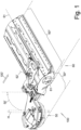
- Figure 1 shows the disc mowing head 50 according to the invention in a typical application, namely as an additional disc mowing head 50 in a mowing unit 100 to a roller mowing head 60, whose mowing track 60* is considerably wider due to a roller blade shaft 61 with its rotation axis 61' lying horizontally, transversely to the mowing direction 100' of the mowing unit 100.
- the disc mowing head 50 In the working position shown - from which it can usually be folded up about a horizontal folding axis 62' lying at an angle to the mowing direction 100' into a transport position above the roller mowing head 60 - the disc mowing head 50 has a significantly narrower mowing track 50* which runs laterally at least partially next to the mowing track 60* and slightly overlaps with it.
- the disc mowing head 50 When an obstacle H approaches on this mowing track 50*, the disc mowing head 50 is pivoted about an upright pivot axis 50' in the direction of the center of the mowing track 60*, deflected by contact with the obstacle H, and then pivoted back into the starting position shown by means of an invisible spring, usually a gas pressure spring, the preload of which is usually adjustable through the kidney-shaped opening in the top of the housing of the additional disc mowing head 50.
- an invisible spring usually a gas pressure spring, the preload of which is usually adjustable through the kidney-shaped opening in the top of the housing of the additional disc mowing head 50.
- the vertical section of the Figure 2 shows that the cutting blades 3 rotate about an axis of rotation 3' which is upright during mowing operation, usually vertical - the axial direction 10, which is usually also the vertical 10 during mowing operation - and thereby mow off approaching cuttings M such as blades of grass on their front side 100' in the mowing direction.
- the cutting blades can have an upward angle of attack in order to initially deflect the cut cuttings M S1, S2 upwards.
- the center of the height of the cutting blades 3 at their outer free end can be defined as the blade level 3".
- the cutting blades 3 - as the view of the Figure 3b from below, there are four cutting blades 3 distributed around the circumference - in this case they are not attached directly to the upright, rotating blade shaft 1, but in the peripheral area of a mowing disk 6, which is attached to the lower free end of the blade shaft 1 and rotates in the cutting blade plane 3".
- the lower end of the blade shaft 1 as well as the underside of the mowing disc 6 are protected by a lower cover 14 attached there, which extends approximately horizontally to approximately the radially outer edge of the mowing disc 6.
- the cutting blades 3 are attached to the mowing disc 6 around an upright cutting blade joint axis 3* so that they can be deflected by a hard crop M.
- the blade shaft 1 is mounted in a plate-shaped upper housing part 2a which lies approximately horizontally during mowing operation and is driven by a motor 12 which sits thereon and is protected by an upper cover 13 which extends above it.
- the housing 2 comprises a housing rotating part 2b with an annular rotating plate 2b2 - the inner ring - which is mounted so as to be rotatable relative to the peripheral edge region of the housing upper part 2a, in particular in a plane parallel to the cutting blade plane 3", and from whose outer edge a peripheral wall 2b1 attached thereto extends downwards to the height or just above the cutting blades 3.
- the housing rotating part 2b is only set in rotation by contacting and rolling its outer circumference on an obstacle H sliding along it, and is preferably not operatively connected to the knife shaft 1.
- the peripheral wall 2b1 which essentially serves to collect stones hit by the cutting blades 3 as well as the separated
- the device is constructed from two radially successive layers 17, 18 which are fastened to the outer circumference of the rotating ring 2b2, e.g. by means of an outer edge element 15 which runs radially outside the two layers of the housing 2.
- the outer edge element 15 is a finite piece of a tensile, elastic band, rubberized at least on the outside, preferably a rubberized steel band 15.
- Bolts 16 projecting radially inwards can be attached to this edge element 15, in particular one of them being a threaded bolt 16.1, onto which the 1st, more flexible and often lighter, wall layer 17 in the form of a film 17 and then the 2nd, less flexible and often heavier, wall layer 18 in the form of individual wall panels 18 or wall tongues 18 connected to one another at the upper end are then threaded radially from the inside by means of corresponding through-openings.
- the 1st wall layer 17 projects downwards over the 2nd wall layer 18, in particular by at least 30%, better at least 50%, better at least 70% of the axial extension of the 2nd wall layer 18.
- This outer edge element 15 is then placed around the circumference of the inner ring 2b2 and a threaded bolt 16.1 is fastened opposite the rotating ring 2b1 to pre-fix the outer edge element 15.
- the threaded bolt 16.1 is preferably located in the middle of the length of the edge element 15.
- Additional bolts 16 present along the edge element 15 - which do not have to have an external thread like the threaded bolt 16.1 - can be inserted into corresponding recesses, usually blind holes, in the outer circumference of the inner ring 2b1.
- this outer edge element 15 which are then closely adjacent in the circumferential direction U due to the corresponding length of the edge element 15, are clamped against one another in the circumferential direction U by means of a circumferential clamping device 20 which is accessible from above, until the outer edge element 15 presses the two layers 17, 18 of the circumferential wall 2b1 in their upper end region against the inner ring 2b2 with a predetermined radial contact force, from where the layers 17, 18 extend downwards with free ends.
- the circumferential clamping device 20 can comprise two stable, non-flexible, end angles 22, each of which is fastened, for example screwed, with one of its legs to one of the end regions of the finite edge element 15, so that their other legs lying adjacent to one another can be clamped against one another in the circumferential direction U by means of a clamping screw 21 and thus the edge element 15 is also clamped in the circumferential direction U.
- the through openings in the two layers 17, 18 of the circumferential wall 2b1 should be dimensioned accordingly large in the circumferential direction U, in particular designed as elongated holes and/or likewise the recesses, usually blind holes in the circumference of the inner ring 2b2.
- a scraper 4 in the form of a sheet metal angle is attached to the underside of the upper housing part 2a in such a way that a scraper leg 4a protruding downwards into the housing extends from the fastening leg lying parallel to the rotary plate 2b2 close to the inner surface of the peripheral wall 2b1 up to a distance 7, as shown in Figure 3b visible, and this stripping leg 4a is additionally inclined to the axial direction 10, the in this case coinciding rotation axes 1', 2' and 3'.
- the scraper 4 which does not rotate during operation like the upper housing part 2a, is prevented from rolling against an obstacle H when the rotating housing part 2b rotates - as shown in Figure 3b visible - rotated so that the scraper leg 4a scrapes off the compressed cuttings kM deposited on the inner surface of the peripheral wall 2b1.
- the scraper leg 4a is inclined so that the rear end in the direction of rotation of the peripheral wall 2b1 is further away from the inner side of the peripheral wall 2b1 than its front end.
- two such scraper legs 4a are arranged in between in a mirror image to the radial direction 11, each at the same distance from the inner surface of the peripheral wall 2b1, so that such scraping takes place independently of the direction of rotation of the peripheral wall 2b1 - which changes when the arrangement is changed at the left or right end of the roller mowing head 60.
- FIG. 2 shows, not only the cutting blades 3 are attached to the rotatable mowing disc 6, but also clearing blades 5, preferably at the same fastening position in the circumferential direction of the mowing disc 6 as the cutting blades 3.
- the clearing blades 5 also consist of a sheet metal angle and comprise a clearing leg 5a which rises at an angle to the blade plane 3", i.e. during mowing operation mostly the horizontal plane, from the mowing disc 6 upwards, here at an angle radially outwards and upwards to a height distance 9 to the underside of the inner ring 2b2, and which thus rotates with the mowing disc 6 and the cutting blades 3.
- the clearing blade 5, in particular its clearing leg 5a which protrudes from the outer end of its fastening leg, which is arranged in particular lower than the scraper 4, is positioned in such a way that it can rotate past the stationary, non-rotating scrapers 4, in particular their vertically extending scraper legs 4a, at a relatively small distance 8, i.e. close to them, with the scraper leg 4a and the clearing leg 5a being vertically, i.e. in axial Direction 10, overlap.
Landscapes
- Life Sciences & Earth Sciences (AREA)
- Environmental Sciences (AREA)
- Harvester Elements (AREA)
Description
- Die Erfindung betrifft einen Scheiben-Mähkopf, bei dem ein oder mehrere Schneidmesser um eine aufrechte Achse in einer meist horizontalen Ebene rotieren können und bei mehreren in der gleichen Ebene rotierenden Schneidmessern diese häufig an einer rotierend angetriebenen Tragscheibe befestigt sind weshalb vorliegend solche Mähköpfe, auch im Rahmen der vorliegenden Erfindung, Scheiben-Mähköpfe genannt werden, selbst wenn keine Tragscheibe vorhanden ist und das wenigstens eine Schneidmesser direkt an einer Messerwelle befestigt ist.
- Ein solcher Scheiben-Mähkopf kann beispielsweise als Pfosten-Freimäher an einem dann meist größeren Walzen-Mähkopf, bei dem eine Messerwelle um eine liegende Messerachse rotiert, beweglich und über dessen Mäh-Spur seitlich vorstehend befestigt sein, um durch federnde Anlage um dort auftauchende Hindernisse wie einen Pfosten sehr exakt herumgeführt zu werden.
- Ein solcher Pfosten-Freimäher in der Bauform als Scheiben-Mähkopf ist prinzipiell aus der Patentanmeldung
DE 101 22 407 A1 bekannt. - Dabei besteht wie bei allen Mähköpfen das Problem, dass von dem Schneidmesser getroffene harte Gegenstände wie Steine oder Ast-Abschnitte mit hoher Geschwindigkeit radial weggeschleudert werden, weshalb die Umfangswände von Mähköpfen immer auch die Funktion eines Steinschlag-Schutzes erfüllen müssen und entsprechend ausgebildet sind.
- Dabei besteht an dem in Fahrtrichtung vorderen Abschnitt der Umfangswand der Zielkonflikt, dass die Umfangswand einerseits nach radial außen stabil und steif genug ausgebildet sein muss, um nach vorn weggeschleuderte z.B. Steine im Gehäuse zurückzuhalten, andererseits nach radial innen biegsam genug ausgebildet sein muss, um das abzumähende Gras unter der vorderen Umfangswand hindurch in den Wirkbereich des Schneidmessers eintreten zu lassen, ohne es vorher flach zu drücken.
- Die Druckschrift
JP 2001 231330 A - Ferner wird auf die Druckschriften
US 3 727 386 A ,JP 2019 141003 A US 3 727 386 A undES 2 478 715 B1 - Es ist daher die Aufgabe gemäß der Erfindung, einen Scheiben-Mähkopf, insbesondere ein Gehäuse hierfür, zur Verfügung zu stellen, der dieses Problem minimiert sowie ein Verfahren zu seiner Herstellung.
- Diese Aufgabe wird durch die Merkmale der Ansprüche 1 und 14 gelöst. Vorteilhafte Ausführungsformen ergeben sich aus den Unteransprüchen.
- Hinsichtlich eines Scheiben-Mähkopfes mit einem Hauben-artigen, unten wenigstens teilweise offenen Gehäuse, in oder unterhalb dessen ein Schneidmesser rotierend um eine aufrechte Rotationsachse antreibbar ist, wird diese Aufgabe dadurch gelöst, dass als Steinschlagschutz die Umfangswand des Gehäuses zwei in radialer Richtung aufeinander folgende, separat Wand-Lagen aufweist, die vorzugsweise einander kontaktieren und über den Umfang des Gehäuses durchgehen.
- Die so aufgebaute Umfangswand ist zumindest in ihrem unteren Bereich nach radial innen sehr elastisch, sodass sie von dem abzumähenden Gras nach innen umgebogen werden kann ohne das Gras flach zu drücken, andererseits zumindest in dem oberen Bereich darüber nach radial außen aber ausreichend stabil und steif in radialer Richtung ist, um einen ausreichenden Steinschlagschutz zu bieten, also das Wegfliegen von durch das Schneidmesser beschleunigten Teilen aus dem Gehäuse heraus zu verhindern.
- Dabei ist die äußere Wand-Lage - für sich alleine betrachtet - im montierten Zustand, also wenn nur diese eine Wandlage montiert wäre, in radialer Richtung, zumindest nach radial innen, biegsamer als die allein montierte innere Wand-Lage.
- Vorzugsweise steht die biegsamere, äußere Wand-Lage nach unten über die steifere Wand-Lage vor und reicht insbesondere bis unmittelbar oberhalb der Rotationsebene des Schneidmessers, sodass vom Schneidmesser getroffene feste Körper wie Steine höchstens in horizontaler Richtung wegfliegen können und durch die Schwerkraft und den Bewuchs nach kurzer Distanz gestoppt werden, aber nicht auf einer ansteigenden Flugbahn wegfliegen können.
- Insbesondere steht die biegsamere, äußere Wand-Lage nach unten um
- mindestens 2 cm, besser mindestens 3 cm, besser mindestens 4 cm besser mindestens 5 cm
und/oder - um mindestens 15 %, besser mindestens 30 %, besser mindestens 40 % besser mindestens 50 % der Höhe der steiferen Wand-Lage (L2) vor.
- Die beiden Wandlagen stehen zumindest an ihrem oberen Rand miteinander in Kontakt, da sie zwischen einem oberen, um die beiden Wandschichten herum verlaufenden, äußeren Randelement und dem Außenumfang eines vorzugsweise parallel zur Schneid-Ebene liegenden Innen-Ring gehalten werden, insbesondere verklemmt sind, sodass dieses insbesondere obere Randelement, samt der beiden Wandlagen leicht lösbar am Innen-Ring befestigt ist und insbesondere festgespannt ist.
- Unter leicht lösbar wird in diesem Zusammenhang das Lösen ohne Werkzeug oder nur mit einem Standard-Werkzeug wie einem Schraubendreher oder Schraubenschlüssel verstanden und dies innerhalb von weniger als 1 Minute., besser weniger als 30 Sekunden, denn diese beiden Wandschichten sind Verschleißteile und müssen relativ oft gewechselt werden.
- Die gesamte Einheit aus Innen-Ring, Umfangswand und äußerem Randelement - das sogenannte Gehäuse-Drehteil - ist drehbar um eine Drehachse, die insbesondere identisch mit der Rotationsachse der Schneidmesser ist, drehbar, insbesondere um den Umfang eines plattenförmigen Gehäuse-Oberteiles.
- Beim Herumführen des Scheiben-Mähkopfes um ein Hindernis wie etwa ein Verkehrsschild rollt das gummierte äußere Randelement an dem Außenumfang des Hindernisses ab und beschädigt dieses nicht und zwischen beiden besteht eine ausreichend große Haftreibung, sodass das Gehäuse-Drehteil hierdurch zuverlässig in Drehung versetzt wird.
- Deshalb muss auch der Steinschlagschutz über den gesamten Umfang umlaufend gleich ausgebildet sein, da im Gegensatz zu einem Walzen-Mähkopf, bei dem als Steinschlagschutz nach vorne häufig ein Kettenvorhang verwendet wird, jeder der Umfangsbereiche der nach vorn gerichtete Umfangsbereich sein kann.
- Der Zusammenhalt zwischen den einzelnen Elementen besteht dadurch, dass das obere äußere Randelement ein endliches, zugfestes streifenförmiges Randelement ist, insbesondere ein Stahlband, mit einer Gummierung zumindest auf seiner Außenseite, welches aber ausreichend elastisch ist, um um den Außenumfang des Innen-Ringes herumgelegt werden zu können.
- Vorzugsweise stehen von diesem äußeren Randelement Bolzen, die an ihm befestigt sind, radial nach innen vor und ragen durch die erste und zweite Wand-Lage hindurch, die auf diese Gewindebolzen mit entsprechenden Durchgangsöffnungen aufgefädelt werden können.
- Der radiale Überstand über die innere der beiden Wandschichten nach innen wird zur Befestigung benutzt, indem er in entsprechende Ausnehmungen, insbesondere Sacklöcher, im Außenumfang des Innen-Ringes eingesteckt werden kann.
- Einer der Bolzen befindet sich etwa in der Mitte der umlaufenden Länge des äu-ßeren Randelementes, ist als Gewinde-Bolzen ausgebildet und dient einer Vorfixierung mittels Verschrauben an einer Stelle des Außenumfanges des Innen-Ringes.
- Jeweils ein Spannelement, insbesondere ein - in der Aufsicht winkelförmiger - Endwinkel ist an jeweils einem Ende des endlichen Randelementes befestigt. Die beiden anderen, gegeneinander weisenden, Schenkel des Endwinkels können gegeneinander in Umfangsrichtung verschraubt werden, wodurch das obere Randelement mit starker Vorspannung am Außenumfang des Innen-Ringes anliegt und die beiden Lagen zwischen äußerem Randelement und dem Innen-Ring verklemmt werden.
- Die Umfangswand, insbesondere deren biegsame äußere Wandlage, ist in Umfangsrichtung durchgängig vorhanden, ggfs. mit einer Überlappungsstelle in Umfangsrichtung.
- Dadurch ist eine einfachere Herstellung aus einem endlichen Teil statt aus einem ringförmig geschlossenen Teil, welches immer an den Durchmesser des Gehäuses angepasst sein muss, möglich.
- Die zweite, steifere Wand-Lage ist dabei vorzugsweise die innere Wand-Lage, denn dadurch wird verhindert, dass die dann äußere biegsame Wand-Lage durch den Luftstrom der nach radial innen gerichtet ist und fast unvermeidbar durch das rotierende Schneidmesser erzeugt wird, diese biegsame Schicht radial nach innen saugt und diese dadurch funktionslos macht.
- Die zweite, steifere Wand-Lage besteht zumindest im unteren Teil aus in Umfangsrichtung aufeinander folgende, ggfs. auch geringfügig beabstandete oder überlappende, Wandteile, insbesondere einzelne Wand-Platten, die aber auch im oberen Bereich miteinander verbunden sein können zu einer bandförmigen zweiten Wand-Lage, die durch Schlitzungen von unten her lediglich nach unten frei auslaufende einzelne Wand-Zungen aufweist.
- Die Flexibilität der einzelnen Zungen ist dadurch größer als bei einem über die gesamte Höhe umlaufenden Band der zweiten steiferen Wandschicht.
- Die erste biegsamere Wand-Lage, die vorzugsweise radial außen liegt, besteht vorzugsweise aus einer flexiblen Folie oder einem Gewebe, vorzugsweise aus Kunststoff.
- Die erste biegsamere Wand-Lage, die vorzugsweise radial außen angeordnet ist, ragt weiter nach unten als die zweite Wandlage, die vorzugsweise radial innen angeordnet ist, und zwar vorzugsweise um mindestens 50 %, besser mindestens 100 % der axialen Erstreckung der ersten Wand-Lage. Dadurch kann das sich von vorne nähernde, abzumähende Ende Gras diesen Überstand de der leichteren Wand-Lage, etwa einer flexiblen Folie oder einem flexiblen Gewebe, unter dem unteren Ende der zweiten, stabileren Wand-Lage leicht nach innen umbiegen, ohne selbst flachgedrückt zu werden.
- Die steifere Wand-Lage besteht vorzugsweise auch aus Kunststoff beispielsweise aus Vulcolan.
- Die äußere, biegsame Wand-Lage hat vorzugsweise eine Biegesteifigkeit von unter 5 N/mm2, insbesondere unter 3 N/mm2, insbesondere unter 3 N/mm2, insbesondere unter 1 N/mm2,
- Die innere, steifere Wand-Lage hat insbesondere eine Biegesteifigkeit zwischen 5 N/mm2 und 30 N/mm2, insbesondere zwischen 7 N/mm2 und 22 N/mm2, insbesondere zwischen 9 N/mm2 und 16 N/mm2, dass er nicht durch das sich annähernde Gras umgebogen werden muss.
- Dabei dient die steifere, innere Wand-Lage primär dem Steinschlagschutz, und ist auch die verschleißfestere Schicht, die als Verschleißschutz für die biegsamere äußere Wand-Lage dient, die zwar nur einen geringen Schutz für leichte, nach außen wegfliegenden Teile bietet, aber vor allem dem radial von außen nach innen in den Messerbereich eintretende Gras nur einen geringen Widerstand entgegensetzt.
- Deshalb besitzt die äußere, biegsame Wand-Lage vorzugsweise eine Härte zwischen 30 Shore und 3 Shore, insbesondere zwischen 20 Shore und 3 Shore, insbesondere zwischen 10 Shore und 3 Shore:
Die innere, steifere Wand-Lage hat insbesondere eine Härte zwischen 50 Shore und 90 Shore, insbesondere zwischen 60 Shore und 80 Shore, insbesondere zwischen 65 Shore und 75 Shore. - Die erste, hinsichtlich zumindest des Flächengewichtes, leichtere Wand-Lage hat vorzugsweise ein Flächengewicht zwischen 1,1 kg/m2. und 1,6 kg/m2, insbesondere zwischen 1,25 kg/m2 und 1,55 kg/m2, insbesondere zwischen 1,35 kg/m2. und 1,45 kg/m2.
- Die zweite, hinsichtlich zumindest des Flächengewichtes, schwerere Wand-Lage hat vorzugsweise ein Flächengewicht zwischen 2,0 kg/m2. und 6,0 kg/m2, insbesondere zwischen 3,0 kg/m2 und 4,5 kg/m2, insbesondere zwischen 3,5 kg/m2. und 4,0 kg/m2.
- Unter Flächengewicht wird dabei das Gewicht pro Flächeneinheit entlang der Hauptebene der jeweiligen Schicht verstanden.
- Die äußere biegsame Wand-Lage hat vorzugsweise ein spezifisches Gewicht zwischen 1,1 kg/m3. und 2,0 kg/m3, insbesondere zwischen 1,4 kg/m3 und 1,7 kg/m3, insbesondere zwischen 1,5 kg/m3. und 1,6 kg/m3.
- Die innere steifere Wand-Lage hat vorzugsweise ein spezifisches Gewicht zwischen 0,8 kg/m3. und 1,7 kg/m3, insbesondere zwischen 1,1 kg/m3 und 1,4 kg/m3, insbesondere zwischen 1,2 kg/m3. und 1,3 kg/m3 ihr spezifisches Gewicht kann also durchaus geringer sein als das der äußeren, biegsameren Wandlage, da hierbei die sehr viel größere Dicke, insbesondere um den Faktor 5, insbesondere um den Faktor 10, insbesondere um den Faktor 20, der inneren Wandlage gegenüber der äußeren Wandlage eine Rolle spielt.
- Da für beide Schichten vorzugsweise Kunststoff verwendet wird und KunststoffMaterialien mit unterschiedlichen spezifischen Gewichten und Biegesteifigkeiten vielfältig am Markt vorhanden sind, können Biegesteifigkeit, Flächengewicht und spezifisches Gewicht sehr gut an die Art des abzumähenden Bewuchses angepasst werden.
- Der gesamte Scheiben-Mähkopf ist vorzugsweise in der Aufsicht betrachtet rotationssymmetrisch aufgebaut, sodass die Schneidmesser-Achse und die Drehachse der Umfangswand vorzugsweise identisch sind.
- Vorzugsweise ist innerhalb der Umfangswand des Gehäuses ein Abstreifer nahe an der Umfangswand angeordnet und die Innenseite der Umfangswand, meist die gesamte Umfangswand, relativ zum Abstreifer in Umfangsrichtung beweglich ist.
- Dadurch schabt der Abstreifer an der Innenseite der Umfangswand anhaftendes Mähgut während der Relativbewegung ab.
- Insbesondere ist zu diesem Zweck entweder die Innenseite der Umfangswand oder der Abstreifer um die Rotationsachse der Umfangswand drehbar.
- Vorzugsweise ist die Umfangswand des haubenartigen, unten wenigstens teilweise offenen Gehäuses drehbar gegenüber einem feststehenden, nicht rotierenden, Gehäuse-Oberteil und an der Unterseite des Gehäuse-Oberteils innerhalb der Umfangswand der Abstreifer angeordnet, der einen bis nahe an die Innenseite der Umfangswand heranreichenden und vom Gehäuse-Oberteil nach unten ragenden Abstreif-Schenkel aufweist.
- Durch die Relativbewegung zwischen Gehäuse-Oberteil und Umfangswand schabt der Abstreifer, insbesondere mit seinem nach unten abragenden, also aufrechtstehenden, Abstreif-Schenkel, das an der Innenfläche der Umfangswand angehaftete Mähgut ab.
- Die Relativbewegung wird in der Regel dadurch bewirkt, dass der Scheiben-Mähkopf zum Abmähen von Bewuchs nahe bis an ein Hindernis heran, wie etwa einen Baum oder ein Verkehrsschild, benutzt wird, und hierfür ein Teil des Gehäuses des Scheiben-Mähkopfes, zum Beispiel mit dem Außenumfang seiner Umfangswand an diesem Hindernis während des Entlangfahrens oder Herumfahrens abrollt und hierdurch die Relativbewegung zwischen Umfangswand und Gehäuse-Oberteil erzielt wird.
- Alternativ kann die Relativ-Bewegung vom Antrieb des Schneidmessers aus bewirkt werden, wobei die Umfangswand relativ zum Gehäuse-Oberteil über ein Zerkleinerungs-Getriebe mit einer stark untersetzten Drehzahl vom Schneidmesser-Antrieb aus angetrieben werden kann.
- Zusätzlich zu dem Abstreifer sollte ein Räummesser vorhanden sein, welches vorzugsweise rotierend im Gehäuse angeordnet ist und vorzugsweise in der Höhe mit dem Abstreifer, insbesondere mit dessen Abstreifer-Schenkel, überlappt - weshalb das Räummesser auch in der Höhe über dem Schneidmesser angeordnet ist - und radial innerhalb des Abstreifers rotiert nahe an dessen Abstreif-Schenkel vorbei.
- Dadurch gelangt das vom Abstreifer abgelöste komprimierte Mähgut sofort in den Wirkbereich des Räummessers und wird zuverlässig von diesem zerkleinert bevor es herabfällt auf dem Untergrund.
- Das Räummesser kann mit der gleichen Drehzahl rotieren wie das Schneidmesser.
- Insbesondere sind die Schneidmesser-Achse und/oder die Räummesser-Achse und/oder die Drehachse, mit der die Umfangswand relativ zum Gehäuse-Oberteil rotiert, identisch.
- Vorzugsweise weist das Räummesser einen mit seinem freien Ende nach oben weisenden Räummesser-Schenkel auf, welcher in der Höhe mit dem Abstreifer überlappt.
- Das Räummesser kann mit seinem etwa horizontal verlaufenden Befestigungsschenkel direkt oder indirekt mit dem wenigstens einen Schneidmesser verbunden sein kann, was eine besonders einfache Konstruktion ergibt.
- In vielen Fällen sind nicht ein, sondern über den Umfang verteilt mehrere Schneidmesser vorhanden, die dann - meist gelenkig um eine Hochachse - am Außenumfang einer rotierenden Messerscheibe befestigt sind, die von dem Schneidmesser-Antrieb rotierend in einer im Mähbetrieb etwa horizontalen Ebene angetrieben wird.
- Die Räummesser können dann ebenfalls an dieser Messerscheibe befestigt werden, sei es drehfest oder ebenfalls gelenkig um eine Hochachse, was dem Ausweichen von Hindernissen möglichst ohne Zerstörung des Messers dienen soll.
- In der Regel dreht sich die Umfangswand des Gehäuses immer nur in eine Richtung relativ zum Gehäuse-Oberteil. Damit der Abstreifer eine gute Ablösewirkung erzielt, ist er schräggestellt zur radialen und/oder tangentialen Richtung und besitzt einen in Drehrichtung der Umfangswand zunehmenden Abstand zu seiner Drehachse. Dadurch ist er in der Lage, mit seiner Vorderkante, die der Innenumfangswand radial am nächsten steht, das dort anhaftende Mähgut abzuschaben und durch die Schrägstellung radial nach innen zu leiten, vorzugsweise in den Wirkbereich des Räummessers hinein.
- Das Räummesser, insbesondere dessen nach oben aufragender Messer-Schenkel, steht vorzugsweise schräg zur Rotationsachse, um 30° bis 110°, insbesondere um 50° bis 90°, insbesondere um 60° bis 80°.
- Unter einem nahen Heranreichen bestimmter Bauteile zueinander wird vorzugsweise ein Abstand von maximal 1,0 cm, besser maximal 0,5 cm, besser maximal 0,3 cm zwischen den jeweiligen beiden Bauteilen verstanden.
- Der Abstreif-Schenkel des Abstreifers sollte in radialer Richtung relativ kurz sein, um während des Entlanggleitens des abgelöstes Mähgutes entlang des schräg stehenden Abstreif-Schenkels noch kein Herabfallen auf den Untergrund zu ermöglichen, bevor dieses komprimierte Mähgut radial anschließend weiter innen das Räummesser zum Zerkleinern erreicht hat, also eine radiale Erstreckung von maximal 5 cm, besser maximal 4 cm, besser maximal 3 cm, besser maximal 2 cm.
- Um das leichtere Eintreten des Bewuchses in den Wirkbereich des Schneidmessers zu ermöglichen, ist die Umfangswand, vor allem in ihrem nach unten frei auslaufenden unteren Endbereich, vor allem nach radial innen, möglichst elastisch ausgebildet und besitzt eine Biegesteifigkeit von unter 3 N/mm2, insbesondere unter 2 N/mm2, insbesondere unter 1 N/mm2.
- Hinsichtlich des Verfahrens zum Befestigen der Umfangswand an dem Innenring am Rest des Hauben-artigen, unten offenen Gehäuses, in oder unterhalb welchem ein Schneidmesser um eine aufrechte Achse rotiert, insbesondere bei einem Scheiben-Mähkopf wie zuvor beschrieben, wird die bestehende Aufgabe dadurch gelöst, dass das endliche äußere Randelement mit daran gehaltener äußerer und innerer Wand-Lage am Außenumfang des Innen-Ringes angelegt, dann um diesen herumgebogen und an dem Außenumfang fixiert wird, was vorzugsweise durch Verspannen der beiden Enden des biegsamen, zugfesten äu-ßeren Randelementes gegeneinander erfolgt.
- Biegsam ist das Randelement vorzugsweise um eine quer zu seiner Erstreckungsrichtung liegende Achse, wobei es so montiert wird, dass diese Biegeachse parallel zur Rotationsachse der Schneidmesser verläuft.
- Vorzugsweise enthält das Randelement ein Stahlband oder Stahlseile, wobei die Breite des bandförmigen Randelementes im montierten Zustand aufrecht steht und dessen Dicke in radialer Richtung liegt.
- In einer konkreten Vorgehensweise wird auf die auf einer Seite des äußeren biegsamen Randelements vorstehenden Radialbolzen zunächst die äußere Wand-Lage und dann die innere Wand-Lage, die jeweils entsprechende Durchgangsöffnung aufweisen, aufgesteckt.
- Anschließend erfolgt eine Vorfixierung, indem ein etwa in der Mitte der Länge des Randelementes vorhandener als Gewindebolzen ausgebildeter Bolzen, der also ein Außengewinde besitzt, gegenüber dem Innen-Ring fixiert, insbesondere durch diesen hindurchgesteckt und vorzugsweise von innen her gegenüber diesem verschraubt wird oder auch von außen in eine Gewindebohrung des Innenrings eingeschraubt wird.
- Die beiden Enden des Randelementes werden mittels einer Spannvorrichtung anschließend in Umfangsrichtung gegeneinander verspannt und damit das Landelement gegen den Außenumfang des Innen-Ringes an gepresst. Zu diesem Zweck ist an jedem Ende des Randelementes je ein in der Aufsicht L-förmiger Endwinkel als Spannelement vorhanden, die beide in Umfangsrichtung gegeneinander Mittels einer Spannschraube verschraubt werden können.
- Das automatisch und ständig sich an den Innenflächen des Gehäuses, insbesondere an der Innenfläche von dessen Umfangswand, anhaftende, abgetrennte komprimierte Mähgut wird vorzugsweise ständig abgelöst, insbesondere mechanisch abgelöst und vorzugsweise das abgelöste komprimierte Mähgut automatisch ständig zerkleinert.
- Letzteres ist vor allem dann wichtig, wenn dieses abgelöste komprimierte Mähgut nicht aus dem Gehäuse nach oben abgeführt wird, sondern auf den Untergrundzurück fallen soll als kleinteiliger Mulch.
- Deshalb wird das abgelöste komprimierte Mähgut im Gehäuse mit Hilfe des gleichen Antriebes zerkleinert, der auch das Schneidmesser antreibt.
- Das Ablösen des komprimierten Mähgutes von der Umfangswand geschieht mittels einer Relativbewegung in Umfangsrichtung, insbesondere einer rotierenden Relativbewegung, der Umfangswand des Gehäuses zum feststehenden Rest des Gehäuses, dem Gehäuse-Oberteil welches aus diesem Grund zweiteilig ausgebildet ist, durch einen Abstreifer am feststehenden Rest.
- Die Relativbewegung kann durch Abrollen der Umfangswand an einem Hindernis bewirkt werden, während das Gehäuse-Oberteil diese Abroll-Bewegung nicht mitmacht, sondern in Drehrichtung stillsteht.
- Die Relativbewegung kann auch auf andere Art und Weise bewirkt werden, beispielsweise durch den Antrieb des Schneidmessers bewirkt werden, wobei die Umfangswand relativ zum Gehäuse-Oberteil bei weitem nicht so schnell rotieren muss und auch nicht rotieren sollte wie das Schneidmesser relativ zum Gehäuse-Oberteil, sodass in diesem Fall die Umfangswand mit einer stark, vorzugsweise mindestens um den Faktor 10, besser um den Faktor 20, untersetzten Drehzahl vom Schneidmesser-Antrieb aus angetrieben werden könnte.
- Ausführungsformen gemäß der Erfindung sind im Folgenden beispielhaft näher beschrieben. Es zeigen:
- Figur 1:
- eine Mäh-Einheit aus einem Walzen-Mähkopf und einem an dessen einen Endbereich befestigten Scheiben-Mähkopf als Zusatz-Scheiben-Mähkopf,
- Figur 2:
- einen Vertikalschnitt durch den Scheiben-Mähkopf der
Figur 1 , - Figur 3a:
- eine Aufsicht von oben auf den Scheiben-Mähkopf gemäß der Linie A - A in
Figur 2 , - Figur 3b:
- eine Ansicht von unten auf den Scheiben-Mähkopf gemäß der Linie B - B in
Figur 2 . -
Figur 1 zeigt den erfindungsgemäßen Scheiben-Mähkopf 50 in einem typischen Anwendungsfall, nämlich als Zusatz-Scheiben-Mähkopf 50 in einer Mäh-Einheit 100 zu einem Walzen-Mähkopf 60, dessen Mähspur 60* wesentlich breiter ist aufgrund einer mit ihrer Rotationsachse 61' horizontal, quer zur Mäh-Richtung 100' der Mäh-Einheit 100, liegenden Walzen-Messerwelle 61. - Der Scheiben-Mähkopf 50 besitzt in der dargestellten Arbeitsstellung - aus der er meist um eine horizontal, schräg zur Mäh-Richtung 100' liegende, Klappachse 62' hochgeklappt werden kann in eine Transportstellung über dem Walzen-Mähkopf 60 - eine deutlich schmalere Mäh-Spur 50*, die sich seitlich zumindest teilweise neben der Mäh-Spur 60* verläuft und geringfügig mit dieser überlappt.
- Bei einem sich auf dieser Mähspur 50* annähernden Hindernis H wird der Scheiben-Mähkopf 50 um eine aufrechte Schwenkachse 50' verschwenkt in Richtung der Mitte der Mähspur 60*, ausgelenkt durch Kontakt mit dem Hindernis H, und danach wieder zurückgeschwenkt in die dargestellte Ausgangsstellung mittels einer nicht sichtbaren Feder, meist einer Gasdruck-Feder, deren Vorspannung meist einstellbar ist durch die hier Nieren-förmige Öffnung in der Oberseite des Gehäuses des Zusatz-Scheiben-Mähkopfes 50.
- Dadurch kann der Walzen-Mähkopf 60 seine Mäh-Richtung 100' ohne Änderung fortsetzen, und der Bewuchs wird bis nahe an das Hindernis H heran abgemäht auf der Seite der Mail-Einheit 100.
- Der Vertikalschnitt der
Figur 2 lässt erkennen, dass die Schneidmesser 3 um eine im Mäh-Betrieb aufrecht stehende, meist vertikal stehende, Rotationsachse 3' - der axialen Richtung 10, die im Mähbetrieb meist auch die Vertikale 10 ist - rotieren und dadurch an ihrer in Mäh-Richtung 100' vorderen Seite sich annäherndes Mähgut M wie etwa Grashalme abmähen. Die Schneidmesser können dabei einen Anstellwinkel nach oben aufweisen zum Ablenken des abgemähten Mähgutes M S1, S2 zunächst nach oben. - Als Messerebene 3" kann dabei die Mitte der Höhe der Schneidmesser 3 an ihren äußeren freien Ende definiert werden.
- Die Schneidmesser 3 - wie die Ansicht der
Figur 3b von unten zeigt, handelt es sich dabei um vier über den Umfang verteilte Schneidmesser 3 - sind in diesem Fall nicht direkt an der aufrecht stehenden, rotierenden Messerwelle 1 befestigt, sondern im Umfangsbereich einer Mäh-Scheibe 6, die am unteren freien Ende der Messerwelle 1 befestigt ist und in der Schneidmesser-Ebene 3" rotiert. - Das untere Ende der Messerwelle 1 sowie die Unterseite der Mähscheibe 6 sind durch eine dort angebrachte untere Abdeckung 14 geschützt, die etwa horizontal liegend bis etwa zum radial äußeren Rand der Mäh-Scheibe 6 reicht.
- Die Schneidmesser 3 sind dabei um eine aufrechte Schneidmesser-Gelenkachse 3* an der Mäh-Scheibe 6 befestigt, sodass sie von einem harten Mähgut M ausgelenkt werden können.
- Die Messerwelle 1 ist in einem plattenförmigen, im Mäh-Betrieb etwa horizontal liegenden, Gehäuse-Oberteil 2a gelagert und wird von einem darauf sitzenden Motor 12 angetrieben, der von einer sich darüber hinweg erstreckenden oberen Abdeckung 13 geschützt ist.
- Das Gehäuse 2 umfasst neben dem Gehäuse-Oberteil 2a ein Gehäuse-Drehteil 2b mit einer ringförmigen Dreh-Platte 2b2 - dem Innen-Ring -, die gegenüber dem umfänglichen Randbereich des Gehäuse-Oberteiles 2a drehbar, insbesondere in einer Ebene parallel zur Schneidmesser-Ebene 3" - gelagert ist, und von deren äußeren Rand sich eine daran befestigte Umfangswand 2b1 nach unten erstreckt bis auf die Höhe oder knapp oberhalb der Schneidmesser 3.
- Das Gehäuse-Drehteil 2b wird lediglich in Drehung versetzt durch Kontaktieren und Abrollen seines äußeren Umfanges an einem daran entlang gleitenden Hindernisses H, und ist vorzugsweise nicht mit der Messerwelle 1 wirkverbunden.
- Erfindunqswesentlich ist, dass die Umfangswand 2b1, die im Wesentlichen dazu dient, von den Schneidmessern 3 getroffene Steine sowie das abgetrennte Mähgut an einem Wegfliegen in radialer Richtung 11 über den Umfang des Gehäuses 2 hinaus abzuhalten, aus zwei radial aufeinanderfolgenden Lagen 17, 18 aufgebaut ist, die am Außenumfang des Dreh-Ringes 2b2 befestigt sind, z.B. mittels eines radial außerhalb der beiden Schichten des Gehäuses 2 umlaufenden äußeren Randelementes 15.
- Um beim Abrollen an einem Hindernis H eine gute Friktion sicherzustellen und gleichzeitig ein einfaches Wechseln der Umfangswand 2b1 oder von dessen Teilen - die Verschleißteile sind - zu ermöglichen, ist das äußere Randelement 15 ein endliches Stück eines zugfesten, elastischen, zumindest auf der Außenseite gummierten, Bandes, vorzugsweise eines gummierten Stahlbandes 15.
- An diesem Randelement 15 können nach radial innen ragende Bolzen 16, insbesondere einer davon ein Gewinde-Bolzen 16.1, befestigt sein, auf die dann radial von innen zunächst die 1., flexiblere und oft leichtere, Wand-Lage 17 in Form einer Folie 17 und danach die 2., weniger flexible und oft schwerere, Wand-Lage 18 in Form von einzelnen Wand-Platten 18 oder am oberen Ende miteinander verbundenen Wand-Zungen 18 mittels entsprechender Durchgangsöffnungen aufgefädelt werden. Dabei steht im montierten Zustand die 1. Wand-Lage 17 nach unten über die 2. Wand-Lage 18 vor, insbesondere um mindestens 30 %, besser mindestens 50 %, besser mindestens 70 % der axialen Erstreckung der 2. Wandschicht 18.
- Anschließend wird dieses äußere Randelement 15 um den Umfang des Innen-Ringes 2b2 gelegt und ein Gewinde-Bolzen 16.1 gegenüber dem Dreh-Ring 2b1 befestigt zur Vorfixierung des äußeren Randelementes 15. Dabei befindet sich der Gewinde-Bolzen 16.1 vorzugsweise in der Mitte der Länge des Randelementes 15.
- Weitere entlang des Randelementes 15 vorhandene Bolzen 16 - die kein Außengewinde wie der Gewinde-Bolzen 16.1 aufweisen müssen - können dabei in entsprechende Ausnehmungen, meist Sacklöcher, in den Außenumfang des Innen-Ringes 2b1 gesteckt werden.
- Anschließend werden die in Umfangsrichtung U dann aufgrund entsprechender Länge des Randelementes 15 nahe benachbarten Enden dieses äußere Randelementes 15 mittels einer Umfangs-Spannvorrichtung 20, die von oben her zugänglich ist, in Umfangsrichtung U gegeneinander gespannt, bis das äußere Randelement 15 mit einer vorgegebenen radialen Anpresskraft die beiden Lagen 17, 18 der Umfangswand 2b1 in deren oberen Endbereich gegen den Innen-Ring 2b2 pressen, von wo die Lagen 17, 18 sich frei endend nach unten erstrecken.
- Die Umfangs-Spannvorrichtung 20 kann zwei stabile, nicht flexible, Endwinkel 22 umfassen, die jeweils mit einem ihrer Schenkel an je einem der Endbereiche des endlichen Randelementes 15 befestigt, beispielsweise verschraubt, sind, sodass deren zueinander benachbart liegende andere Schenkel mittels einer Spannschraube 21 in Umfangsrichtung U gegeneinander gespannt werden können und damit auch das Randelement 15 in Umfangsrichtung U gespannt wird.
- Da hierbei die in der Regel in Umfangsrichtung U fix am Randelement 15 positionierten Bolzen 16 ihre Position in Umfangsrichtung ändern, sollten die Durchgangsöffnungen in den beiden Lagen 17, 18 der Umfangswand 2b1 in Umfangsrichtung U entsprechend groß dimensioniert sein, insbesondere als Langlöcher gestaltet und/oder ebenso die Ausnehmungen, meist Sacklöcher im Umfang des Innen-Ringes 2b2.
- Ferner ist ein Abstreifer 4 in Form eines Blech-Winkels an der Unterseite des Gehäuse-Oberteils 2a so befestigt, dass von dem parallel zur Dreh-Platte 2b2 liegenden Befestigungs-Schenkel ein nach unten in das Gehäuse hinein abragender Abstreif-Schenkel 4a sich nahe bis auf einen Abstand 7 an die Innenfläche der Umfangswand 2b1 erstreckt, wie in
Figur 3b ersichtlich, und dieser Abstreif-Schenkel 4a zusätzlich schräg gestellt ist zur axialen Richtung 10, den in diesem Fall übereinstimmenden Rotationsachsen 1', 2' und 3'. - Dadurch wird der - wie das Gehäuse-Oberteil 2a - im Betrieb nicht rotierende Abstreifer 4 bei einer Drehung des Gehäuse-Drehteiles 2b durch Abrollen an einem Hindernis H - wie in
Figur 3b ersichtlich - so gedreht, dass der Abstreif-Schenkel 4a das an der Innenfläche der Umfangswand 2b1 abgelagerte komprimierte Mähgut kM abschabt. Hierfür ist der Abstreif-Schenkel 4a so schräg gestellt, dass das in Drehrichtung der Umfangs Wand 2b1 hintere Ende weiter von der Innenseite der Umfangswand 2b1 entfernt ist als sein vorderes Ende. - Vorzugsweise sind in diesem Fall zwei solche Abstreif-Schenkel 4a spiegelbildlich zur radialen Richtung 11 dazwischen angeordnet, mit jeweils gleichem Abstand zur Innenfläche der Umfangswand 2b1, um unabhängig von der Drehrichtung der Umfangswand 2b1 - die sich bei Wechsel der Anordnung am linken oder rechten Ende des Walzen-Mähkopfes 60 ändert - ein solches Abschaben stattfindet.
- Wie
Figur 2 zeigt, sind an der rotierbaren Mähscheibe 6 nicht nur die Schneidmesser 3 befestigt, sondern auch Räummesser 5, vorzugsweise auf der gleichen Befestigungsposition in Umfangsrichtung der Mähscheibe 6 wie die Schneidmesser 3. - Die Räummesser 5 bestehen ebenfalls aus einem Blechwinkel und umfassen einen schräg zur Messerebene 3", also im Mähbetrieb meist der horizontalen Ebene, von der Mähscheibe 6 nach oben, hier schräg nach radial außen und oben bis auf einen Höhen-Abstand 9 zur Unterseite des Innenringes 2b2, aufsteigenden Räum-Schenkel 5a, der somit mit der Mähscheibe 6 und den Schneidmessern 3 mit rotiert. Das Räummesser 5, insbesondere dessen vom äußeren Ende von dessen Befestigungsschenkel, der insbesondere tiefer angeordnet ist als der Abstreifer 4, abragende Räum-Schenkel 5a, ist so positioniert, dass er radial innerhalb der feststehenden, nicht rotierenden Abstreifer 4, insbesondere deren sich in der Höhe erstreckenden Abstreif-Schenkeln 4a in relativ geringem Abstand 8, also nahe an diesen, vorbei rotieren kann, wobei der Abstreif-Schenkel 4a und der Räum-Schenkel 5a in der Höhe, also in axialer Richtung 10, überlappen.
- Auf diese Art und Weise wird das vom Abstreifer 4 meist in großen Stücken abgelöste komprimierte Mähgut kH von dem Räum -Schenkel 5a zerkleinert.
-
- 1
- Messerwelle, Scheiben-Messerwelle
- 1'
- Rotationsachse
- 2
- Gehäuse
- 2a
- Gehäuse-Oberteil
- 2b
- Gehäuse-Drehteil
- 2b1
- Umfangswand
- 2b2
- ringförmige Drehplatte, Innenring
- 2b`
- Rotation-Achse
- 3
- Schneidmesser
- 3'
- Schneidmesser-Rotationsachse
- 3*
- Schneidmesser-Gelenkachse
- 3"
- Messerebene
- 4
- Abstreifer
- 4a
- Abstreif-Schenkel
- 5
- Räummesser
- 5'
- Räummesser-Achse
- 5a
- Räum-Schenkel
- 6
- Mähscheibe
- 7
- Abstand
- 8
- Abstand
- 9
- Abstand
- 10
- axiale Richtung, Vertikale
- 11
- radiale Richtung
- 12
- Motor
- 13
- obere Abdeckung
- 14
- untere Abdeckung
- 15
- äußeres Randelement
- 16
- Gewindebolzen
- 17
- 1. Wandlage, Folie, Gewebe
- 18
- 2. Wandlage, Wandplatte, Wandzunge
- 19
- End-Winkel
- 20
- Spannvorrichtung
- 21
- Spannschraube
- 50
- Scheiben-Mähkopf, Zusatz-Scheiben-Mähkopf
- 60
- Walzen-Mähkopf
- 61
- Messerwelle, Walzen-Messerwelle
- 61'
- Rotationsachse
- 62'
- Klappachse
- 100
- Mäh-Einheit
- 100`
- Mäh-Richtung
- H
- Hindernis
- kM
- komprimiertes Mähgut
- U
- Umfangs-Richtung
Claims (15)
- Scheiben-Mähkopf (50), insbesondere Zusatz-Scheiben-Mähkopf (50) zu einem Walzen-Mähkopf (60), umfassend- ein haubenartiges, unten im Wesentlichen offenes Gehäuse (2) mit einer Umfangswand (2b1),- wenigstens ein in oder unterhalb des Gehäuses (2) rotierend um eine aufrechte Schneidmesser-Achse, die Rotationsachse (3'), antreibbares Schneidmesser (3),- einen Innen-Ring (2b2) und- ein oberes, äußeres Randelement (15),
wobei- die Umfangswand (2b1) des Gehäuses (2) in radialer Richtung (11) zwei, sich insbesondere kontaktierende, separate Wand-Lagen (17, 18) aufweist, nämlich- eine radial äußere, 1. Wand-Lage (17) und eine radial innere, 2. Wand-Lage (18),
dadurch gekennzeichnet, dass- die beiden Wand-Lagen (17, 18) zumindest an ihrem oberen Ende einander kontaktieren, indem sie beide zwischen dem oberen, äußeren Randelement (15) und dem Innen-Ring (2b2) gehalten sind, und- das obere äußere Randelement (15) ein endliches Randelement (15) ist. - Scheiben-Mähkopf nach Anspruch 1,
dadurch gekennzeichnet, dass- die äußere Wand-Lage (17) im montierten Zustand alleine betrachtet in radialer Richtung, zumindest nach radial innen, biegsamer ist als die innere Wand-Lage (18),- die äußere, biegsamere Wand-Lage (17) über die innere, steifere Wand-Lage (18) nach unten vorsteht, und
die Umfangswand (2b1)- zumindest in ihrem unteren Bereich nach radial innen so elastisch ist, dass sich annäherndes Gras sie nach radial innen umbiegen kann,- zumindest im oberen Bereich über diesem unteren Bereich nach radial außen ausreichend stabil ist, um als Steinschlagschutz zu dienen,- insbesondere in Umfangsrichtung (U) aufeinanderfolgende, gegebenenfalls auch überlappende, ein oder mehrere Wandteile aufweist. - Scheiben-Mähkopf nach Anspruch 2,
dadurch gekennzeichnet, dass- die äußere, biegsamere Wand-Lage (17) über die innere, steifere Wand-Lage (18) nach unten um- mindestens 2 cm, besser mindestens 3 cm, besser mindestens 4 cm besser mindestens 5 cm
und/oder- um mindestens 15 %, besser mindestens 30 %, besser mindestens 40 % besser mindestens 50 % der Höhe der steiferen Wand-Lage (18) vorsteht. - Scheiben-Mähkopf nach einem der vorhergehenden Ansprüche,
dadurch gekennzeichnet, dass- die beiden Wand-Lagen (17, 18) zumindest an ihrem oberen Ende einander kontaktieren, indem sie beide zwischen einem gemeinsamen, oberen, äußeren Randelement (15) und dem Innen-Ring (2b2) verklemmt sind,- insbesondere das obere Randelement (15) samt der beiden Wand-Lagen (17, 18) leicht lösbar, insbesondere festspannbar, am Innen-Ring (2b2) befestigt ist. - Scheiben-Mähkopf nach einem der vorhergehenden Ansprüche,
dadurch gekennzeichnet, dass- die Umfangswand (2b1) des Gehäuses (2), insbesondere das obere Randelement (15) samt der beiden Wand-Lagen (17, 18) und dem drehbaren Innen-Ring (2b2), drehbar ist gegenüber einem nicht drehbaren, fixen Gehäuse-Oberteil (2a)). - Scheiben-Mähkopf nach einem der vorhergehenden Ansprüche,
dadurch gekennzeichnet, dass- von dem äußeren Randelement (15) aus Bolzen (16) nach radial innen ragen,- wovon insbesondere einer ein Gewinde-Bolzen (16.1) ist, welcher der Vorfixierung des Randelementes (15) am drehbaren Innen-Ring (2b2) dient,- insbesondere die übrigen Bolzen (16) in Ausnehmungen, insbesondere Sacklöcher, im Außenumfang des Innen-Ringes (2b2) einsteckbar sind zur Lagefixierung des Randelementes (15) in der Höhe. - Scheiben-Mähkopf nach einem der vorhergehenden Ansprüche,
dadurch gekennzeichnet, dass- die innere Wand-Lage (18) zumindest im unteren Teil in Umfangsrichtung (U) aufeinanderfolgende, gegebenenfalls auch überlappende, Wandteile, insbesondere einander nicht überlappende separate Wand-Platten oder nur im oberen Bereich miteinander verbundene Wand-Zungen, aufweist
und/oder- die äußere Wand-Lage (17) eine in Umfangsrichtung (U) im Wesentlichen durchgehende, Wand-Lage ist, die insbesondere eine flexible Folie oder flexibles Gewebe umfasst, deren Enden insbesondere in Umfangsrichtung (U) überlappen. - Scheiben-Mähkopf nach einem der vorhergehenden Ansprüche,
dadurch gekennzeichnet, dass- die äußere Wand-Lage (17) eine Biegesteifigkeit von unter 5 N/mm2, insbesondere unter 3 N/mm2, insbesondere unter 2 N/mm2 insbesondere unter 1 N/mm2 aufweist
und/oder- die innere Wand-Lage (18), insbesondere deren Wandschicht-Platten, eine Biegesteifigkeit von über 5 N/mm2, insbesondere von über 20 N/mm2 insbesondere von über 50 N/mm2 insbesondere von über 100 N/mm2 aufweist. - Scheiben-Mähkopf nach einem der vorhergehenden Ansprüche,
dadurch gekennzeichnet, dass- die äußere Wand-Lage (17) eine Härte von zwischen 30 Shore und 3 Shore, insbesondere zwischen 20 Shore und 3 Shore, insbesondere zwischen 10 Shore und 3 Shore aufweist
und/oder- die innere Wand-Lage (18), insbesondere deren Wandschicht-Platten, eine Härte zwischen 50 Shore und 90 Shore, insbesondere zwischen 60 Shore und 80 Shore, insbesondere zwischen 65 Shore und 75 Shore aufweist. - Scheiben-Mähkopf nach einem der vorhergehenden Ansprüche,
dadurch gekennzeichnet, dass- die äußere Wand-Lage (17) ein Flächengewicht zwischen 1,1 kg/m2 und 1,6 kg/m2, insbesondere zwischen 1,25 kg/m2 und 1,55 kg/m2, insbesondere zwischen 1,35 kg/m2 und 1,45 kg/m2 aufweist
und/oder- die innere Wand-Lage (18), insbesondere deren Wandschicht-Platten, ein Flächengewicht zwischen 2,0 kg/m2 und 6,0 kg/m2, insbesondere zwischen 3,0 kg/m2 und 4,5 kg/m2, insbesondere zwischen 3,5 kg/m2 und 4,0 kg/m2 aufweist. - Scheiben-Mähkopf nach einem der vorhergehenden Ansprüche,
dadurch gekennzeichnet, dass- die äußere Wand-Lage (17) ein spezifisches Gewicht zwischen 1,1 kg/m3 und 2,0 kg/m3, insbesondere zwischen 1,4 kg/m3 und 1,7 kg/m3, insbesondere zwischen 1,5 kg/m3 und 1,6 kg/m3 aufweist und/oder- die innere Wand-Lage (18), insbesondere deren Wandschicht-Platten, ein spezifisches Gewicht zwischen 0,8 kg/m3 und 1,7 kg/m3, insbesondere zwischen 1,1 kg/m3 und 1,4 kg/m3, insbesondere zwischen 1,2 kg/m3 und 1,3 kg/m3aufweist, insbesondere die Wandschicht-Platten aus Vulculan bestehen. - Scheiben-Mähkopf nach einem der vorhergehenden Ansprüche,
dadurch gekennzeichnet, dass
die innere Wand-Lage (18) eine größere Dicke, insbesondere um den Faktor 5, insbesondere um den Faktor 10, insbesondere um den Faktor 20, gegenüber der äußeren Wand-Lage (17) aufweist. - Scheiben-Mähkopf nach einem der vorhergehenden Ansprüche,
dadurch gekennzeichnet, dass- je zwei Rotationsachsen aus der Schneidmesser-Achse (3') und/oder einer Räummesser-Achse (5') eines Räummessers (5), welches rotierend in dem Gehäuse (2) angeordnet ist, und/oder einer Drehachse (2a') der Umfangswand (2a) maximal um 5 cm, besser maximal um 3 cm, besser maximal 2 cm zueinander beabstandet sind,- insbesondere mindestens je zwei Rotationsachsen identisch sind. - Verfahren zum Befestigen der drehbaren Umfangswand (2b1) am feststehenden Gehäuse-Oberteil (2a) eines haubenartigen, unten im wesentlichen offenen Gehäuses (2) eines Scheiben-Mähkopfes (50), in oder unterhalb welchem ein Schneidmesser (3) rotierend um eine aufrechte Schneidmesser-Achse (3') antreibbar ist, dadurch gekennzeichnet, dass- ein endliches äußere, zugfestes, biegsames Randelement (15) mit daran gehaltener äußerer Wand-Lage (17) sowie innerer Wand-Lage (18) um den Außenumfang eines drehbaren Innen-Ringes (2b2) des Gehäuses (2) herum gelegt und an diesem fixiert wird,- insbesondere durch Verspannen der beiden Enden des Randelementes (15) gegeneinander.
- Verfahren nach Anspruch 14,
dadurch gekennzeichnet, dass- auf nach radial innen vorstehende Bolzen (16) des biegsamen äußeren Randelementes (15) eine bandförmige äußere Wand-Lage (17) und eine, insbesondere bandförmige, innere Wand-Lage (18) mittels entsprechender Durchgangsöffnungen aufgesteckt werden,- ein etwa in der Mitte der Länge des äußeren Randelementes (15) vorhandener, mit einem Außengewinde versehener, Gewindebolzen (16.1) gegenüber dem Innen-Ring (2b2) verschraubt wird als Vorfixierung,- das biegsame Randelement (15) um den Außenumfang des Innen-Rings (2b2) herumgelegt wird und dabei die nach radial innen vorstehende Bolzen (16) in entsprechende Ausnehmungen des Innen-Rings (2b2) eingesteckt werden,- die Enden des endlichen, äußeren Randelementes (15) an einem Spannelement, insbesondere je einem End-Winkel (19) fixiert werden,- die beiden Spannelemente, insbesondere End-Winkel (19), in Umfangsrichtung (U) gegeneinander verspannt werden, insbesondere mit einer Spannschraube (21).
Priority Applications (1)
| Application Number | Priority Date | Filing Date | Title |
|---|---|---|---|
| HRP20241593TT HRP20241593T1 (hr) | 2021-11-12 | 2022-11-09 | Glava za košenje sa diskom i postupak za pričvršćivanje perifernog zida glave za košenje sa diskom |
Applications Claiming Priority (2)
| Application Number | Priority Date | Filing Date | Title |
|---|---|---|---|
| DE202021106204.5U DE202021106204U1 (de) | 2021-11-12 | 2021-11-12 | Scheiben-Mähkopf |
| DE102021129538.6A DE102021129538A1 (de) | 2021-11-12 | 2021-11-12 | Scheiben-Mähkopf sowie Verfahren zum Befestigen der Umfangswand |
Publications (2)
| Publication Number | Publication Date |
|---|---|
| EP4179865A1 EP4179865A1 (de) | 2023-05-17 |
| EP4179865B1 true EP4179865B1 (de) | 2024-09-18 |
Family
ID=84330358
Family Applications (1)
| Application Number | Title | Priority Date | Filing Date |
|---|---|---|---|
| EP22206383.6A Active EP4179865B1 (de) | 2021-11-12 | 2022-11-09 | Scheiben-mähkopf sowie verfahren zum befestigen der umfangswand des scheiben-mähkopf |
Country Status (3)
| Country | Link |
|---|---|
| EP (1) | EP4179865B1 (de) |
| DK (1) | DK4179865T3 (de) |
| HR (1) | HRP20241593T1 (de) |
Families Citing this family (1)
| Publication number | Priority date | Publication date | Assignee | Title |
|---|---|---|---|---|
| CN117941539B (zh) * | 2024-02-04 | 2026-02-17 | 深圳库犸科技有限公司 | 机器人 |
Citations (1)
| Publication number | Priority date | Publication date | Assignee | Title |
|---|---|---|---|---|
| ES2478715B1 (es) * | 2013-01-18 | 2015-06-23 | Javier LANDEIRA CANEDO | Equipo para desbrozado de plantas |
Family Cites Families (5)
| Publication number | Priority date | Publication date | Assignee | Title |
|---|---|---|---|---|
| US3727386A (en) * | 1972-06-06 | 1973-04-17 | Outboard Marine Corp | Flexible rear shield for rotary lawn mower |
| JP3274852B2 (ja) * | 2000-02-25 | 2002-04-15 | 株式会社神島組 | 清掃用アタッチメント |
| DE10122407B4 (de) | 2001-04-10 | 2004-03-04 | Hermann Tacke | Mähvorrichtung zum Mähen eines Bereichs neben einem Tragmittel |
| US20080289194A1 (en) * | 2007-05-24 | 2008-11-27 | M Group, Inc. | Trimmer skirt |
| JP2019141003A (ja) * | 2018-02-22 | 2019-08-29 | 株式会社ササキコーポレーション | 自走式草刈機 |
-
2022
- 2022-11-09 HR HRP20241593TT patent/HRP20241593T1/hr unknown
- 2022-11-09 DK DK22206383.6T patent/DK4179865T3/da active
- 2022-11-09 EP EP22206383.6A patent/EP4179865B1/de active Active
Patent Citations (1)
| Publication number | Priority date | Publication date | Assignee | Title |
|---|---|---|---|---|
| ES2478715B1 (es) * | 2013-01-18 | 2015-06-23 | Javier LANDEIRA CANEDO | Equipo para desbrozado de plantas |
Also Published As
| Publication number | Publication date |
|---|---|
| DK4179865T3 (da) | 2024-11-25 |
| EP4179865A1 (de) | 2023-05-17 |
| HRP20241593T1 (hr) | 2025-01-31 |
Similar Documents
| Publication | Publication Date | Title |
|---|---|---|
| DE3149887C2 (de) | ||
| DE3102598C2 (de) | ||
| DE2424377A1 (de) | Scheibenmaeher | |
| EP0913078A1 (de) | Mähwerk für Rasenmäher | |
| DE2505679A1 (de) | Umlaufende maehvorrichtung | |
| WO1989006898A1 (fr) | Tondeuse a tambour | |
| EP4179865B1 (de) | Scheiben-mähkopf sowie verfahren zum befestigen der umfangswand des scheiben-mähkopf | |
| DE3212178A1 (de) | Maehbalken mit scheiben | |
| CH637263A5 (de) | Schleppergetriebene kreiselmaehmaschine. | |
| DE2843782C2 (de) | Kreiselheuwerbungsmaschine zum Schwadenlegen oder Schwadenwenden oder zum Zetten/Wenden | |
| DE3114676C2 (de) | Schneidrotor für eine Mähmaschine | |
| EP4179864A1 (de) | Scheiben-mähkopf sowie verfahren zum abmähen von bewuchs | |
| EP1000533B1 (de) | Pflückvorrichtung zum Ernten von Halmfrüchten | |
| EP0554560B1 (de) | Rasenmäher | |
| DE102021129539A1 (de) | Scheiben-Mähkopf sowie Verfahren zum Abmähen von Bewuchs | |
| DE3439226C2 (de) | Mähgerät | |
| DE202021106204U1 (de) | Scheiben-Mähkopf | |
| DE3501133A1 (de) | Kreiselmaeher | |
| DE2703301A1 (de) | Maehmaschine | |
| EP3281511B1 (de) | Fahrbare mähvorrichtung | |
| DE60100061T2 (de) | Mulchmäher | |
| EP1958493B1 (de) | Mähmaschine | |
| DE102021129538A1 (de) | Scheiben-Mähkopf sowie Verfahren zum Befestigen der Umfangswand | |
| DE202021106205U1 (de) | Scheiben-Mähkopf | |
| DE102005055621B3 (de) | Maschine zur Ernte stängelartiger Pflanzen |
Legal Events
| Date | Code | Title | Description |
|---|---|---|---|
| REG | Reference to a national code |
Ref country code: HR Ref legal event code: TUEP Ref document number: P20241593T Country of ref document: HR |
|
| PUAI | Public reference made under article 153(3) epc to a published international application that has entered the european phase |
Free format text: ORIGINAL CODE: 0009012 |
|
| STAA | Information on the status of an ep patent application or granted ep patent |
Free format text: STATUS: THE APPLICATION HAS BEEN PUBLISHED |
|
| AK | Designated contracting states |
Kind code of ref document: A1 Designated state(s): AL AT BE BG CH CY CZ DE DK EE ES FI FR GB GR HR HU IE IS IT LI LT LU LV MC ME MK MT NL NO PL PT RO RS SE SI SK SM TR |
|
| P01 | Opt-out of the competence of the unified patent court (upc) registered |
Effective date: 20230526 |
|
| STAA | Information on the status of an ep patent application or granted ep patent |
Free format text: STATUS: REQUEST FOR EXAMINATION WAS MADE |
|
| 17P | Request for examination filed |
Effective date: 20230707 |
|
| RBV | Designated contracting states (corrected) |
Designated state(s): AL AT BE BG CH CY CZ DE DK EE ES FI FR GB GR HR HU IE IS IT LI LT LU LV MC ME MK MT NL NO PL PT RO RS SE SI SK SM TR |
|
| GRAP | Despatch of communication of intention to grant a patent |
Free format text: ORIGINAL CODE: EPIDOSNIGR1 |
|
| STAA | Information on the status of an ep patent application or granted ep patent |
Free format text: STATUS: GRANT OF PATENT IS INTENDED |
|
| INTG | Intention to grant announced |
Effective date: 20240408 |
|
| GRAS | Grant fee paid |
Free format text: ORIGINAL CODE: EPIDOSNIGR3 |
|
| GRAA | (expected) grant |
Free format text: ORIGINAL CODE: 0009210 |
|
| STAA | Information on the status of an ep patent application or granted ep patent |
Free format text: STATUS: THE PATENT HAS BEEN GRANTED |
|
| AK | Designated contracting states |
Kind code of ref document: B1 Designated state(s): AL AT BE BG CH CY CZ DE DK EE ES FI FR GB GR HR HU IE IS IT LI LT LU LV MC ME MK MT NL NO PL PT RO RS SE SI SK SM TR |
|
| REG | Reference to a national code |
Ref country code: GB Ref legal event code: FG4D Free format text: NOT ENGLISH |
|
| REG | Reference to a national code |
Ref country code: CH Ref legal event code: EP |
|
| REG | Reference to a national code |
Ref country code: IE Ref legal event code: FG4D Free format text: LANGUAGE OF EP DOCUMENT: GERMAN |
|
| REG | Reference to a national code |
Ref country code: DE Ref legal event code: R096 Ref document number: 502022001703 Country of ref document: DE |
|
| REG | Reference to a national code |
Ref country code: DK Ref legal event code: T3 Effective date: 20241122 |
|
| REG | Reference to a national code |
Ref country code: LT Ref legal event code: MG9D |
|
| PG25 | Lapsed in a contracting state [announced via postgrant information from national office to epo] |
Ref country code: NO Free format text: LAPSE BECAUSE OF FAILURE TO SUBMIT A TRANSLATION OF THE DESCRIPTION OR TO PAY THE FEE WITHIN THE PRESCRIBED TIME-LIMIT Effective date: 20241218 |
|
| PG25 | Lapsed in a contracting state [announced via postgrant information from national office to epo] |
Ref country code: GR Free format text: LAPSE BECAUSE OF FAILURE TO SUBMIT A TRANSLATION OF THE DESCRIPTION OR TO PAY THE FEE WITHIN THE PRESCRIBED TIME-LIMIT Effective date: 20241219 Ref country code: FI Free format text: LAPSE BECAUSE OF FAILURE TO SUBMIT A TRANSLATION OF THE DESCRIPTION OR TO PAY THE FEE WITHIN THE PRESCRIBED TIME-LIMIT Effective date: 20240918 |
|
| REG | Reference to a national code |
Ref country code: HR Ref legal event code: ODRP Ref document number: P20241593T Country of ref document: HR Payment date: 20241128 Year of fee payment: 3 |
|
| PG25 | Lapsed in a contracting state [announced via postgrant information from national office to epo] |
Ref country code: BG Free format text: LAPSE BECAUSE OF FAILURE TO SUBMIT A TRANSLATION OF THE DESCRIPTION OR TO PAY THE FEE WITHIN THE PRESCRIBED TIME-LIMIT Effective date: 20240918 |
|
| PG25 | Lapsed in a contracting state [announced via postgrant information from national office to epo] |
Ref country code: LV Free format text: LAPSE BECAUSE OF FAILURE TO SUBMIT A TRANSLATION OF THE DESCRIPTION OR TO PAY THE FEE WITHIN THE PRESCRIBED TIME-LIMIT Effective date: 20240918 |
|
| REG | Reference to a national code |
Ref country code: NL Ref legal event code: MP Effective date: 20240918 |
|
| PG25 | Lapsed in a contracting state [announced via postgrant information from national office to epo] |
Ref country code: RS Free format text: LAPSE BECAUSE OF FAILURE TO SUBMIT A TRANSLATION OF THE DESCRIPTION OR TO PAY THE FEE WITHIN THE PRESCRIBED TIME-LIMIT Effective date: 20241218 |
|
| PG25 | Lapsed in a contracting state [announced via postgrant information from national office to epo] |
Ref country code: RS Free format text: LAPSE BECAUSE OF FAILURE TO SUBMIT A TRANSLATION OF THE DESCRIPTION OR TO PAY THE FEE WITHIN THE PRESCRIBED TIME-LIMIT Effective date: 20241218 Ref country code: NO Free format text: LAPSE BECAUSE OF FAILURE TO SUBMIT A TRANSLATION OF THE DESCRIPTION OR TO PAY THE FEE WITHIN THE PRESCRIBED TIME-LIMIT Effective date: 20241218 Ref country code: LV Free format text: LAPSE BECAUSE OF FAILURE TO SUBMIT A TRANSLATION OF THE DESCRIPTION OR TO PAY THE FEE WITHIN THE PRESCRIBED TIME-LIMIT Effective date: 20240918 Ref country code: GR Free format text: LAPSE BECAUSE OF FAILURE TO SUBMIT A TRANSLATION OF THE DESCRIPTION OR TO PAY THE FEE WITHIN THE PRESCRIBED TIME-LIMIT Effective date: 20241219 Ref country code: FI Free format text: LAPSE BECAUSE OF FAILURE TO SUBMIT A TRANSLATION OF THE DESCRIPTION OR TO PAY THE FEE WITHIN THE PRESCRIBED TIME-LIMIT Effective date: 20240918 Ref country code: BG Free format text: LAPSE BECAUSE OF FAILURE TO SUBMIT A TRANSLATION OF THE DESCRIPTION OR TO PAY THE FEE WITHIN THE PRESCRIBED TIME-LIMIT Effective date: 20240918 |
|
| REG | Reference to a national code |
Ref country code: HR Ref legal event code: T1PR Ref document number: P20241593 Country of ref document: HR |
|
| PG25 | Lapsed in a contracting state [announced via postgrant information from national office to epo] |
Ref country code: NL Free format text: LAPSE BECAUSE OF FAILURE TO SUBMIT A TRANSLATION OF THE DESCRIPTION OR TO PAY THE FEE WITHIN THE PRESCRIBED TIME-LIMIT Effective date: 20240918 |
|
| PG25 | Lapsed in a contracting state [announced via postgrant information from national office to epo] |
Ref country code: IS Free format text: LAPSE BECAUSE OF FAILURE TO SUBMIT A TRANSLATION OF THE DESCRIPTION OR TO PAY THE FEE WITHIN THE PRESCRIBED TIME-LIMIT Effective date: 20250118 Ref country code: PT Free format text: LAPSE BECAUSE OF FAILURE TO SUBMIT A TRANSLATION OF THE DESCRIPTION OR TO PAY THE FEE WITHIN THE PRESCRIBED TIME-LIMIT Effective date: 20250120 |
|
| PG25 | Lapsed in a contracting state [announced via postgrant information from national office to epo] |
Ref country code: RO Free format text: LAPSE BECAUSE OF FAILURE TO SUBMIT A TRANSLATION OF THE DESCRIPTION OR TO PAY THE FEE WITHIN THE PRESCRIBED TIME-LIMIT Effective date: 20240918 Ref country code: SM Free format text: LAPSE BECAUSE OF FAILURE TO SUBMIT A TRANSLATION OF THE DESCRIPTION OR TO PAY THE FEE WITHIN THE PRESCRIBED TIME-LIMIT Effective date: 20240918 |
|
| PG25 | Lapsed in a contracting state [announced via postgrant information from national office to epo] |
Ref country code: ES Free format text: LAPSE BECAUSE OF FAILURE TO SUBMIT A TRANSLATION OF THE DESCRIPTION OR TO PAY THE FEE WITHIN THE PRESCRIBED TIME-LIMIT Effective date: 20240918 |
|
| PG25 | Lapsed in a contracting state [announced via postgrant information from national office to epo] |
Ref country code: EE Free format text: LAPSE BECAUSE OF FAILURE TO SUBMIT A TRANSLATION OF THE DESCRIPTION OR TO PAY THE FEE WITHIN THE PRESCRIBED TIME-LIMIT Effective date: 20240918 |
|
| PG25 | Lapsed in a contracting state [announced via postgrant information from national office to epo] |
Ref country code: PL Free format text: LAPSE BECAUSE OF FAILURE TO SUBMIT A TRANSLATION OF THE DESCRIPTION OR TO PAY THE FEE WITHIN THE PRESCRIBED TIME-LIMIT Effective date: 20240918 Ref country code: CZ Free format text: LAPSE BECAUSE OF FAILURE TO SUBMIT A TRANSLATION OF THE DESCRIPTION OR TO PAY THE FEE WITHIN THE PRESCRIBED TIME-LIMIT Effective date: 20240918 |
|
| PG25 | Lapsed in a contracting state [announced via postgrant information from national office to epo] |
Ref country code: SK Free format text: LAPSE BECAUSE OF FAILURE TO SUBMIT A TRANSLATION OF THE DESCRIPTION OR TO PAY THE FEE WITHIN THE PRESCRIBED TIME-LIMIT Effective date: 20240918 |
|
| REG | Reference to a national code |
Ref country code: DE Ref legal event code: R097 Ref document number: 502022001703 Country of ref document: DE |
|
| PG25 | Lapsed in a contracting state [announced via postgrant information from national office to epo] |
Ref country code: MC Free format text: LAPSE BECAUSE OF FAILURE TO SUBMIT A TRANSLATION OF THE DESCRIPTION OR TO PAY THE FEE WITHIN THE PRESCRIBED TIME-LIMIT Effective date: 20240918 |
|
| PG25 | Lapsed in a contracting state [announced via postgrant information from national office to epo] |
Ref country code: LU Free format text: LAPSE BECAUSE OF NON-PAYMENT OF DUE FEES Effective date: 20241109 |
|
| PLBE | No opposition filed within time limit |
Free format text: ORIGINAL CODE: 0009261 |
|
| STAA | Information on the status of an ep patent application or granted ep patent |
Free format text: STATUS: NO OPPOSITION FILED WITHIN TIME LIMIT |
|
| 26N | No opposition filed |
Effective date: 20250619 |
|
| REG | Reference to a national code |
Ref country code: BE Ref legal event code: MM Effective date: 20241130 |
|
| PG25 | Lapsed in a contracting state [announced via postgrant information from national office to epo] |
Ref country code: SE Free format text: LAPSE BECAUSE OF FAILURE TO SUBMIT A TRANSLATION OF THE DESCRIPTION OR TO PAY THE FEE WITHIN THE PRESCRIBED TIME-LIMIT Effective date: 20240918 |
|
| PG25 | Lapsed in a contracting state [announced via postgrant information from national office to epo] |
Ref country code: BE Free format text: LAPSE BECAUSE OF NON-PAYMENT OF DUE FEES Effective date: 20241130 |
|
| PG25 | Lapsed in a contracting state [announced via postgrant information from national office to epo] |
Ref country code: IE Free format text: LAPSE BECAUSE OF NON-PAYMENT OF DUE FEES Effective date: 20241109 |
|
| REG | Reference to a national code |
Ref country code: CH Ref legal event code: U11 Free format text: ST27 STATUS EVENT CODE: U-0-0-U10-U11 (AS PROVIDED BY THE NATIONAL OFFICE) Effective date: 20251201 |
|
| REG | Reference to a national code |
Ref country code: HR Ref legal event code: ODRP Ref document number: P20241593 Country of ref document: HR Payment date: 20251030 Year of fee payment: 4 |
|
| PGFP | Annual fee paid to national office [announced via postgrant information from national office to epo] |
Ref country code: DE Payment date: 20251029 Year of fee payment: 4 |
|
| PGFP | Annual fee paid to national office [announced via postgrant information from national office to epo] |
Ref country code: AT Payment date: 20260113 Year of fee payment: 4 |
|
| PGFP | Annual fee paid to national office [announced via postgrant information from national office to epo] |
Ref country code: IT Payment date: 20251201 Year of fee payment: 4 Ref country code: DK Payment date: 20251125 Year of fee payment: 4 |
|
| PGFP | Annual fee paid to national office [announced via postgrant information from national office to epo] |
Ref country code: HR Payment date: 20251030 Year of fee payment: 4 Ref country code: FR Payment date: 20251126 Year of fee payment: 4 |
|
| PGFP | Annual fee paid to national office [announced via postgrant information from national office to epo] |
Ref country code: CH Payment date: 20251201 Year of fee payment: 4 |
|
| PG25 | Lapsed in a contracting state [announced via postgrant information from national office to epo] |
Ref country code: HU Free format text: LAPSE BECAUSE OF FAILURE TO SUBMIT A TRANSLATION OF THE DESCRIPTION OR TO PAY THE FEE WITHIN THE PRESCRIBED TIME-LIMIT; INVALID AB INITIO Effective date: 20221109 |
|
| PG25 | Lapsed in a contracting state [announced via postgrant information from national office to epo] |
Ref country code: CY Free format text: LAPSE BECAUSE OF FAILURE TO SUBMIT A TRANSLATION OF THE DESCRIPTION OR TO PAY THE FEE WITHIN THE PRESCRIBED TIME-LIMIT; INVALID AB INITIO Effective date: 20221109 |