EP4184193A1 - Verfahren zur bestimmung eines korrigierten abstandes - Google Patents
Verfahren zur bestimmung eines korrigierten abstandes Download PDFInfo
- Publication number
- EP4184193A1 EP4184193A1 EP22206672.2A EP22206672A EP4184193A1 EP 4184193 A1 EP4184193 A1 EP 4184193A1 EP 22206672 A EP22206672 A EP 22206672A EP 4184193 A1 EP4184193 A1 EP 4184193A1
- Authority
- EP
- European Patent Office
- Prior art keywords
- vehicle
- distance
- correction
- segment
- fixed
- Prior art date
- Legal status (The legal status is an assumption and is not a legal conclusion. Google has not performed a legal analysis and makes no representation as to the accuracy of the status listed.)
- Granted
Links
Images
Classifications
-
- G—PHYSICS
- G01—MEASURING; TESTING
- G01S—RADIO DIRECTION-FINDING; RADIO NAVIGATION; DETERMINING DISTANCE OR VELOCITY BY USE OF RADIO WAVES; LOCATING OR PRESENCE-DETECTING BY USE OF THE REFLECTION OR RERADIATION OF RADIO WAVES; ANALOGOUS ARRANGEMENTS USING OTHER WAVES
- G01S5/00—Position-fixing by co-ordinating two or more direction or position line determinations; Position-fixing by co-ordinating two or more distance determinations
- G01S5/02—Position-fixing by co-ordinating two or more direction or position line determinations; Position-fixing by co-ordinating two or more distance determinations using radio waves
- G01S5/0205—Details
- G01S5/021—Calibration, monitoring or correction
-
- G—PHYSICS
- G01—MEASURING; TESTING
- G01S—RADIO DIRECTION-FINDING; RADIO NAVIGATION; DETERMINING DISTANCE OR VELOCITY BY USE OF RADIO WAVES; LOCATING OR PRESENCE-DETECTING BY USE OF THE REFLECTION OR RERADIATION OF RADIO WAVES; ANALOGOUS ARRANGEMENTS USING OTHER WAVES
- G01S13/00—Systems using the reflection or reradiation of radio waves, e.g. radar systems; Analogous systems using reflection or reradiation of waves whose nature or wavelength is irrelevant or unspecified
- G01S13/74—Systems using reradiation of radio waves, e.g. secondary radar systems; Analogous systems
- G01S13/76—Systems using reradiation of radio waves, e.g. secondary radar systems; Analogous systems wherein pulse-type signals are transmitted
- G01S13/765—Systems using reradiation of radio waves, e.g. secondary radar systems; Analogous systems wherein pulse-type signals are transmitted with exchange of information between interrogator and responder
-
- G—PHYSICS
- G01—MEASURING; TESTING
- G01P—MEASURING LINEAR OR ANGULAR SPEED, ACCELERATION, DECELERATION, OR SHOCK; INDICATING PRESENCE, ABSENCE, OR DIRECTION, OF MOVEMENT
- G01P15/00—Measuring acceleration; Measuring deceleration; Measuring shock, i.e. sudden change of acceleration
- G01P15/02—Measuring acceleration; Measuring deceleration; Measuring shock, i.e. sudden change of acceleration by making use of inertia forces using solid seismic masses
-
- G—PHYSICS
- G01—MEASURING; TESTING
- G01P—MEASURING LINEAR OR ANGULAR SPEED, ACCELERATION, DECELERATION, OR SHOCK; INDICATING PRESENCE, ABSENCE, OR DIRECTION, OF MOVEMENT
- G01P15/00—Measuring acceleration; Measuring deceleration; Measuring shock, i.e. sudden change of acceleration
- G01P15/18—Measuring acceleration; Measuring deceleration; Measuring shock, i.e. sudden change of acceleration in two or more dimensions
-
- G—PHYSICS
- G01—MEASURING; TESTING
- G01S—RADIO DIRECTION-FINDING; RADIO NAVIGATION; DETERMINING DISTANCE OR VELOCITY BY USE OF RADIO WAVES; LOCATING OR PRESENCE-DETECTING BY USE OF THE REFLECTION OR RERADIATION OF RADIO WAVES; ANALOGOUS ARRANGEMENTS USING OTHER WAVES
- G01S5/00—Position-fixing by co-ordinating two or more direction or position line determinations; Position-fixing by co-ordinating two or more distance determinations
- G01S5/02—Position-fixing by co-ordinating two or more direction or position line determinations; Position-fixing by co-ordinating two or more distance determinations using radio waves
- G01S5/0269—Inferred or constrained positioning, e.g. employing knowledge of the physical or electromagnetic environment, state of motion or other contextual information to infer or constrain a position
-
- G—PHYSICS
- G01—MEASURING; TESTING
- G01S—RADIO DIRECTION-FINDING; RADIO NAVIGATION; DETERMINING DISTANCE OR VELOCITY BY USE OF RADIO WAVES; LOCATING OR PRESENCE-DETECTING BY USE OF THE REFLECTION OR RERADIATION OF RADIO WAVES; ANALOGOUS ARRANGEMENTS USING OTHER WAVES
- G01S5/00—Position-fixing by co-ordinating two or more direction or position line determinations; Position-fixing by co-ordinating two or more distance determinations
- G01S5/02—Position-fixing by co-ordinating two or more direction or position line determinations; Position-fixing by co-ordinating two or more distance determinations using radio waves
- G01S5/0294—Trajectory determination or predictive filtering, e.g. target tracking or Kalman filtering
-
- G—PHYSICS
- G01—MEASURING; TESTING
- G01S—RADIO DIRECTION-FINDING; RADIO NAVIGATION; DETERMINING DISTANCE OR VELOCITY BY USE OF RADIO WAVES; LOCATING OR PRESENCE-DETECTING BY USE OF THE REFLECTION OR RERADIATION OF RADIO WAVES; ANALOGOUS ARRANGEMENTS USING OTHER WAVES
- G01S7/00—Details of systems according to groups G01S13/00, G01S15/00, G01S17/00
- G01S7/02—Details of systems according to groups G01S13/00, G01S15/00, G01S17/00 of systems according to group G01S13/00
- G01S7/40—Means for monitoring or calibrating
Definitions
- the invention relates to a method for determining a corrected distance between a mobile transceiver fixed to a vehicle and a fixed transceiver.
- Such methods for determining a distance are for example implemented in methods for locating a vehicle.
- Such a localization method is for example described in the following article: V. Di Pietra et al. : "Loosely Coupled GNSS and UWB with INS Integration for Indoor/Outdoor Pedestrian Navigation", Sensors, 5/11/2020 .
- the distance between the fixed and mobile transceivers is used to correct an estimated position of the vehicle using other sensors.
- the better the precision over the distance the more the precision over the position of the vehicle is improved.
- the distance between the fixed and mobile transceivers is obtained from the instants of transmission and reception of radio signals exchanged between these transceivers.
- These radio signals are electromagnetic waves that propagate at the speed of light.
- a variation in the power of the radio signals received by the fixed and mobile transceivers generally induces a variation in the delays in the mechanism for detecting the time of arrival within the receiver.
- the first strategy consists in using a correction function that is complex and precise but which is difficult to implement and time-consuming to execute.
- a correction function is difficult to implement because it includes a very large number of parameters and it is difficult to precisely adjust each of these parameters.
- the second strategy consists, conversely, in using a correction function that is simple to implement and quick to execute.
- the simplification of the implementation of the correction function is done to the detriment of precision.
- the invention aims to remedy this contradiction by proposing a method for determining the distance between the fixed and mobile transceivers in which the implementation of the correction function can be both simple and fast without necessarily degrading the accuracy of the determined distance.
- the invention also relates to a method for locating a vehicle implementing the above method for determining a distance.
- the invention also relates to a system for determining a distance in accordance with claim 11.
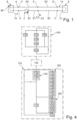
- FIG. 1 represents a vehicle 2 capable of moving along each of the trajectory segments of a predetermined set of several trajectory segments. Each segment begins at a point, hereinafter called “starting point” and ends at a point hereinafter called “end point”. The portion of trajectory which connects the start and end points of the segment is known in advance and fixed. THE vehicle 2 is forced, by mechanical or electronic means, to move only along the segments of this group.
- vehicle 2 is a gondola suspended from cable 4.
- portions of the cable are shown in dotted lines to indicate that only part of the cable 4 has been shown.
- the cable 4 forms a loop which extends between a station 6 of departure and a station 8 of arrival.
- the cable 4 is driven in rotation by a motor in the direction indicated by the arrow 10.
- the rotation of the cable 4 causes the movement of the vehicle 2 between the stations 6 and 8 along a trajectory in the form of a loop imposed by the cable 4.
- the trajectory of vehicle 2 is considered to coincide with the trajectory of cable 4.
- the trajectory of the vehicle 2 here comprises an uphill portion 12 which goes from station 6 to station 8 and a downhill portion 14 which goes from station 8 to station 6.
- uphill 12 and downhill 14 portions are not confused.
- the vehicle 2 comprises a radio transceiver 20 on board this vehicle.
- One or more fixed transceivers located along the path of the vehicle 2 are also provided.
- the fixed transceivers are arranged at regular intervals along the rising portion 12.
- a single fixed transceiver 22 has been shown.
- the transceiver 22 is immobile and its position in a terrestrial reference RT is known in advance and does not change.
- the terrestrial reference RT is fixed without any degree of freedom to the earth.
- the RT frame comprises three axes typically orthogonal to one another.
- the RT frame is the frame known by the term ECEF frame ("Earth Centered, Earth fixed").
- segment S1 and S2 belong to the upward portion 12 of the trajectory while the segments S3 and S4 belong to the downward portion 14 of the trajectory.
- Segment S1 extends from a starting point A to an ending point B.
- Segment S2 extends from point B to an ending point C.
- THE segment S3 extends from a starting point D to a finishing point E.
- Segment S4 extends from point E to an end point F.
- the arrival and departure points of segments S1 and S2 coincide.
- the arrival and departure points of the segments S3 and S4 are combined.
- points B and E are the points, respectively, of the uplink 12 and downlink 14 parts, closest to the transceiver 22.
- the fixed and mobile transceivers are capable of exchanging information frames between them making it possible to measure the distance which separates them. Because of this, subsequently, the segments S1 to S4 are said to be "associated" with the fixed transceiver 22.
- the movement of the vehicle 2 is controlled from a cockpit 38 .
- this post 38 is located in the departure station 6.
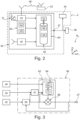
- FIG. 2 represents the vehicle 2 in more detail and in particular a system 30 for locating the vehicle 2 on board this vehicle.
- the system 30 is able to determine the position, the orientation and the speed of the vehicle 2 in the terrestrial reference RT.
- a mobile reference Rb fixed without any degree of freedom to the chassis of the vehicle 2 is defined.
- This reference mark Rb comprises three mutually orthogonal axes noted respectively xb, y b and zb.
- xb and yb axes are in a horizontal plane and the zb axis is vertical.
- the xb axis is oriented and points in the direction the vehicle is moving when it is moving forward.
- the position of the vehicle 2 in the reference RT is expressed by coordinates of the origin of the reference Rb in the reference RT.
- the orientation of the vehicle 2 is expressed by the yaw angle ⁇ , the pitch angle ⁇ and the roll angle ⁇ in English) of the reference Rb defined with respect to a so-called "navigation" reference.
- the orientation of the vehicle is in the form of an orientation matrix from which it is possible to deduce the yaw angle, the pitch angle and the roll angle of the vehicle.
- the orientation of the vehicle can also be in the form of a vector directly comprising the yaw angle, the pitch angle and the roll angle of the vehicle. Subsequently, it is considered that these two scenarios are equivalent and therefore that the orientation of the vehicle includes the angle of yaw, pitch angle and roll angle of the vehicle as long as these three angles can be deduced directly from a matrix or a vector.
- the position, the orientation and the speed determined by the system 30 are delivered on an output 37. Thereafter, the position, the orientation and the speed delivered on the output 37 by the system 30 for an instant tk are noted, respectively, P(k), O(k) and V(k).
- the output 37 is for example connected to a man-machine interface 34 housed in the vehicle 2 is which displays the position, the orientation and the speed determined by the system 30.
- the output 37 can also be connected to the cockpit 38 by via a wireless link or a wired link. In the latter case, the position, the orientation and the speed determined by the system 30 are automatically converted into commands for controlling the drive motor of the cable 4.
- the system 30 comprises a satellite geolocation unit 40, an inertial measurement unit 42 and the transceiver 20.
- the unit 40 is known by the acronym GNSS (“ Global Navigation Satellite System ”). From the satellite signals it receives, the unit 40 generates signals representative of the position and the speed of the vehicle in the reference RT The unit 40 updates its measurements at a frequency F 40. Conventionally, the frequency F 40 is between 0.1 Hz and 20 Hz.
- the unit 42 is known by the acronym IMU (“ Inertial Measurement Unit ”).
- the unit 42 comprises in particular a triaxial accelerometer 44 and a triaxial gyrometer 46. Thanks to these sensors, the unit 42 is capable of measuring the variation in the orientation, the position and the speed of the vehicle 2.
- the measurement axes of the accelerometer 44 and of the gyrometer 46 coincide, respectively, with the axes xb, yb and zb of the reference Rb.
- the accelerometer 44 is arranged such that a positive measurement of vehicle 2's acceleration along the xb axis means that vehicle 2 is accelerating while moving forward.
- the unit 42 updates the acceleration and speed measurements at a high frequency F 42 .
- the frequency F 42 is between 20 Hz and 2000 Hz.
- the frequency F 42 is equal to 200 Hz.
- the transceiver 20 exchanges information frames with the transceiver 22 via a wireless radio link 48. These information frames are exchanged in particular to measure the distance which separates these transceivers 20, 22 from the times of flight of these information frames.
- the transceivers 20, 22 are ultra-wide band or UWB (“Ultra Wide Band”) transceivers.
- UWB Ultra Wide Band
- the term "ultra-wideband transceiver” or “UWB transceiver” here refers to a transceiver that uses a wide band of frequencies to send and receive the information frames.
- a "wide" band of frequencies is a band of frequencies whose width is greater than 0.2f c , where f c is the median frequency of this band of frequencies.
- a wide frequency band is wider than 250 MHz or even wider than 400 MHz.
- the measurement of a distance between the transceivers 20, 22 requires the exchange of several information frames between these transceivers 20, 22 and the measurement of the instants of transmission and reception of these information frames. This exchange of information frames is repeated at a frequency F 20 to update the distance measurement at this frequency.
- the frequency F 20 is smaller than the frequency F 42 .
- the frequency F 20 is ten or fifty times smaller than the frequency F 42 .
- the frequency F 20 is between 0.1 Hz and 20 Hz.
- the instants of transmission and reception of the information frames are obtained by the transceiver 20 housed in the vehicle 2.
- the system 30 comprises a programmable electronic computer 50 This computer 50 is able to acquire the measurements of the units 40 and 42 and the instants of transmission and reception obtained by the transceiver 20. Then, from these measurements, the computer 50 determines the position, the orientation and speed of vehicle 2 in the RT frame.
- the computer 50 comprises a microprocessor 52 and a memory 54 comprising the instructions and the data necessary for the implementation of the method described with reference to the figure 4 .
- the memory 54 includes the instructions of a software module 56 able to determine the position, the orientation and the speed of the vehicle 2 from the measurements acquired when it is executed by the microprocessor 52.
- the module 56 notably implements a fusion algorithm which establishes, on the basis of a previous estimate of the position, of the orientation and of the speed of the vehicle 2 and of new measurements acquired since this previous estimate, a new estimate of the position, orientation and speed of the vehicle 2.
- the fusion algorithm also establishes margins of error on each new estimate.
- this fusion algorithm implements one or more Kalman filters.
- the module 56 implements an architecture known by the term “closed loop” (“closed loop integration scheme” or “closed loop approach”).
- the memory 54 also includes a table 58 which associates with each segment Sn a respective correction function f Sn (d), where the index Sn is the identifier of a segment among the segments S1 to S4.
- Sub-module 60 is known by the English term "Mechanization". For each instant tk, the sub-module 60 constructs a raw estimate of a position P e (k), of an orientation O e (k) and of a speed V e (k) of the vehicle 2.
- the symbol "k” is the sequence number of the instant tk in the temporally ordered sequence ⁇ 0, t 1 , t 2 , ..., t k-1 , tk, ... ⁇ of the instants tk.
- k-1 the sequence number of time t k-1 which immediately precedes time t k .
- the position P e (k), orientation O e (k) and speed V e (k) of the vehicle 2 are each a vector comprising three coordinates.
- the coordinates of the position P e (k) in the frame R T are denoted x e (k), y e (k) and z e (k).
- the orientation coordinates O e (k) are denoted ⁇ e (k), ⁇ e (k) and ⁇ e (k) and the velocity coordinates V e (k) are denoted Vx e (k), Vy e (k) and Vz e (k).
- the frequency of instants tk is less than or equal to frequency F 42 .
- the frequency of instants tk is equal to the frequency F 42 .
- INS Intelligent Navigation System
- the sub-module 61 acquires the instants of transmission and reception obtained by the transceiver 20 and the last position of the vehicle 2 estimated by the sub-module 60. Then, the sub-module 61 delivers to the sub-module 62 a corrected distance calculated from the transmission and reception instants acquired and from the last position of the vehicle 2 acquired. The detailed operation of this sub-module 61 is described with reference to the figure 4 .
- the sub-module 62 corrects the position P e (k), the orientation O e (k) and the speed V e (k) constructed by the sub-module 60 for this instant tk in order to obtain a corrected position P c (k), a corrected orientation O c (k) and a corrected speed V c (k) for this instant tk.
- these particular instants tk are called "instants t m ".
- the symbol "m" is equal to the sequence number of a particular instant tk in the sequence ⁇ 0, t 1 , t 2 , ..., t k-1 , tk, ... ⁇ .
- Each sequence number m is therefore equal to a respective sequence number k.
- the position P e (m), the orientation O e (m) and the velocity V e (m) are equal, respectively, to the position P e (k), the orientation O e (k) and the speed V e (k) constructed for time t k equal to time t m .
- the sequence ⁇ 0, t 1 , t 2 , ..., t m-1 , t m , ... ⁇ of times t m is a subset of the sequence ⁇ 0, t 1 , t 2 , .. ., t k-1 , tk, ... ⁇ .
- the correction by the sub-module 62 is not carried out for each instant tk but only for a part of them.
- the sub-module 62 combines the position P e (m), the orientation O e (m) and the speed V e (m) with respective correction coefficients to obtain the corrected position P c ( m), the corrected orientation O c (m) and the corrected speed V c (m).
- the correction coefficients are updated according to the measurements of the unit 40 and the corrected distance determined by the sub-module 61. The correction coefficients are therefore updated at a frequency lower than the frequency F 42 .
- Sub-module 62 acquires the measurements from unit 40 at a frequency less than or equal to frequency F 42 .
- the measurement acquisition frequency of the unit 40 is equal to the frequency F 40 .
- tg i denotes the instants of acquisition of a new measurement of unit 40.
- These instants tg i form a sequence ⁇ 0, tg 1 , tg 2 , ..., tg i-1 , tg i , ... ⁇ temporally ordered of instants tg i .
- the symbol "i" designates the sequence number of time tg i in this sequence.
- the sub-module 62 updates the correction coefficients each time a new measurement of the unit 40 is acquired and therefore for each instant tg i .
- the instants tg i are less frequent than the instants tk.
- the sub-module 62 also acquires the corrected distance, delivered by the sub-module 61, at a frequency less than or equal to the frequency F 42 .
- the frequency of acquisition of the corrected distance is equal to the frequency F 20 .
- dc j the corrected distance acquired at time to j .
- the symbol "j" is the sequence number of the instant to j in the temporally ordered sequence ⁇ 0, to 1 , to 2 , ..., to j-1 , to j , ... ⁇ of the instants to j .
- the sub-module 62 also updates the correction coefficients each time a new corrected distance dc j is acquired and therefore for each instant to j . Since frequency F 20 is lower than frequency F 42 , there are systematically several instants tk between instants to j-1 and to j .
- each instant tg i and to j corresponds to a respective instant tk of the sequence ⁇ 0, t 1 , t 2 , ..., t k-1 , t k , ... ⁇ .
- the instants tg i and to j are distinct. In other words, at a time tg i when the measurement of the unit 40 is acquired, no new corrected distance is acquired and vice versa. Finally, in this text, the instants t m are equal to the instants at which the sub-module 62 acquires either a measurement of the unit 40 or a new corrected distance.
- the sub-module 62 To update the correction coefficients according to the measurements of the unit 40 and the corrected distance, the sub-module 62 includes a Kalman filter 64. To combine the correction coefficients with the raw estimates delivered by the sub-module 60, the sub-module 62 also comprises an adder 66.
- the filter 64 is known by the acronym ESKF (Error State Kalman Filter) because it estimates corrections to be made to the position, the orientation and the speed estimated by the sub-module 60. More precisely, the filter 64 provides , for each instant t m , a state vector X m
- m contains in particular the correction coefficients to be used to correct the position P e (m), the orientation O e (m) and the speed V e (m).
- the adder 66 For each instant t m , the adder 66 combines the correction coefficients supplied by the filter 64 with the position P e (m), the orientation O e (m) and the speed V e (m) to obtain the corrected position P c (m), the corrected orientation O c (m) and the corrected speed V c (m). For each instant tk subsequent to instant t m and prior to instant t m+1 , no correction is made to the estimates constructed by sub-module 60.
- m contains correction coefficients ⁇ x (m), ⁇ y (m) and ⁇ z (m) of the coordinates, respectively, x e (m), y e ( m) and z e (m) from position P e (m).
- the adder 66 adds these coefficients ⁇ x (m), ⁇ y (m) and ⁇ z (m), respectively, to the coordinates x e (m), y e (m) and z e (m) to obtain the coordinates , respectively, x c (m), y c (m) and z c (m) of the corrected position P c (m).
- m also comprises correction coefficients ⁇ ⁇ (m), ⁇ ⁇ (m) and ⁇ ⁇ (m), respectively, coordinates ⁇ e (m), ⁇ e (m) and ⁇ e (m) of the orientation O e (m).
- the adder 66 adds these coefficients ⁇ ⁇ (m), ⁇ ⁇ (m) and ⁇ ⁇ (m), respectively, to the coordinates ⁇ e (m), ⁇ e (m) and ⁇ e (m) to obtain the coordinates corrected, respectively, ⁇ c (m), ⁇ c (m) and ⁇ c (m) of the orientation O c (m).
- m also comprises three correction coefficients ⁇ v x (m), ⁇ v y (m) and ⁇ v z (m) used to correct, respectively, the coordinates Vx e (m), Vy e (m) and Vz e (m) of the velocity V e (m).
- m is therefore the following vector with fifteen coordinates: [ ⁇ ⁇ (m), ⁇ ⁇ (m), ⁇ ⁇ (m), ⁇ v x (m), ⁇ v y (m), ⁇ v z (m), ⁇ x (m), ⁇ y (m), ⁇ z (m), ⁇ ba x (m), ⁇ ba y (m), ⁇ ba z (m), ⁇ bg x ( m), ⁇ bg y (m), ⁇ bg z (m)] T , where the symbol " T " is the symbol of the transposed operation.
- the filter 64 comprises a prediction block 68 calculating a first state vector X m
- block 68 constructs a prediction X m
- filter 64 is an extended Kalman filter known by the acronym EKF (“Extended Kalman Filter”).
- the gap Y m is known as "innovation".
- the physical quantities measured are the position and the speed measured by the unit 40 and, alternately, the corrected distance delivered by the sub-module 61.
- the block 70 corrects the prediction X m
- block 70 corrects the prediction X m
- m-1 , at times tg i , as a function of position and speed deviations is carried out, for example, as described in Godha2006. Thus, this functionality of block 70 is not described in further detail. Only the correction of the prediction X m
- the coordinates B x , B y , B z are constant and pre-recorded in memory 54.
- Y m dc m - ⁇ m .
- the observation matrix H m is a function of the partial derivative of relation (3) with respect to the various parameters of the state vector X m
- the matrix R m is for example constant and initialized using data on the noise covariance on the measurements of the transmission and reception instants obtained by the transceiver 20.
- the updated error covariance matrix at time t m is calculated using the following relationship (7): P m
- m (I - K m H m )P m
- m contains the margins of error on the estimations of the correction coefficients.
- the adder 66 is a simple adder which adds at the position P e (k), at the orientation O e (k) and at the speed V e (k) the corresponding correction coefficients contained in the state vector X m
- the method begins with a calibration phase 100 .
- this phase 100 the correction functions f Sn associated with each of the segments S1 to S4 are determined.
- the vehicle 2 travels the entire segment S1 starting from point A to point B.
- the transceivers 20 and 22 exchange information frames to allow the measurement of a raw distance between these transceivers 20, 22 from the instants d transmission and reception of these information frames.
- Each exchange of information frames makes it possible to acquire enough transmission and reception times to calculate a raw distance between these transceivers 20 and 22.
- these exchanges are triggered periodically at the frequency F 20 .
- Each exchange therefore takes place during a respective period T 20,j .
- the first information frame is transmitted at a time M 1,j and received by the transceiver 22 at a time M 2,j .
- the second information frame is transmitted at a time M 3,j and received by the transceiver 20 at a time M 4,j .
- the instants M 1,j and M 4,j are measured by the transceiver 20.
- the instants M 2,j and M 3,j are measured by the transceiver 22. Since the instant M 3,j is measured by the transceiver 22, it cannot be transmitted to the transceiver 20 in the second information frame transmitted at this instant.
- the instants M 2,j and M 3,j measured by the transceiver 22 are transmitted to the transceiver 20 in the second information frame transmitted during the following period T 20,j+1 . Because of this delay, the instant to j at which the sub-module 62 acquires the distance dc j occurs well after the end of the period T 20,j .
- the transceiver 20 When the transceiver 20 has measured the times M 1,j and M 4,j and received the measurements M 2,j and M 3,j , during a step 106, the transceiver 20 transmits these measurements to sub-module 61.
- the sub-module 61 calculates a raw distance db j solely from the instants of transmission and reception measured during the period T 20,j .
- a precise distance dp j is measured without using the instants of transmission and reception of the information frames.
- measurements are taken by another sensor independent of the transceivers 20 and 22.
- this other sensor is used only during the calibration phase 100 . It must have a better precision, and typically twice or ten times better, than that on the measurement of the raw distance db j .
- this other sensor is an optical rangefinder temporarily installed along segments S1 to S4.
- the function f S1 is parameterized by the distance d and therefore denoted f S1 (d).
- This function f s1 (d) is fully defined as soon as the values of the constants a s1 , b s1 and d 0,s1 are known.
- the values of the constants a s1 , b s1 and d 0,s1 which minimize the following difference for all the distances dp j measured are calculated:
- a numerical solver is used.
- the function f s1 (d) is associated with the segment S1 in table 58.
- the values of the constants a s1 , b s1 and d 0,s1 are associated with the segment S1 by table 58.
- the table 58 comprises a correction function associated with each of the segments S1 to S4. Most often, the correction functions thus determined are all different from one another.
- the system 30 is used to determine a corrected distance dc j between the transceivers 20 and 22 and to locate the vehicle 2.
- phase 120 of initialization of the system 30 begins immediately after the activation of the system 30, that is to say typically just after it has been energized.
- this phase 120 the various variables and parameters necessary for the execution of the module 56 are initialized. For example, the initial values of the position, of the speed and of the orientation of the vehicle 2 and of the correction coefficients are initialized. There are many algorithms that can quickly obtain these initial values.
- phase 130 of execution of the module 56 begins.
- the module 56 determines and updates the position, the orientation and the speed of the vehicle 2. Thus, this update is performed for each instant tk.
- step 136 comprises an operation 138 during which the accelerometer 44 and the gyrometer 46 measure, respectively, the acceleration and the angular speed of the vehicle 2 and these new measurements are acquired by the computer 50 at the instant tk.
- step 150 of determining the distance between the transceivers 20, 22 is executed. This step 150 is repeated at the frequency F 20 to make available to the sub-module 62 a new corrected distance dc j at each instant to j .
- Operations 152, 154 and 156 are identical to steps 104, 106 and 108 respectively.
- sub-module 61 uses the last position of vehicle 2 estimated by sub-module 60.
- the coordinates of segments S1 to S4 are not used.
- director vectors u v and ub are associated, respectively, with the transceivers 20 and 22.
- the vector u v is fixed with respect to the chassis of the vehicle 2.
- this vector u v moves only if the orientation of the vehicle moves.
- the vector ub is fixed with respect to the transceiver 22. Since the transceiver 22 is stationary, the vector ub does not move.
- the choice of the directions in which the vectors u v and ub point is an arbitrary choice. Indeed, these vectors u v and ub are simply used to identify the relative orientation of the transceivers 20, 22.
- the vectors u v and ub are horizontal. Still to simplify the calculations, the vector u v is chosen as being parallel to the direction xb of the reference frame Rb and of opposite direction to the direction xb. Here, the vector ub is chosen as being parallel and in the same direction as the vector u v when the vehicle is on the segment S1.
- the sub-module 61 identifies the segment on which the vehicle 2 is located from the signs of the cosines of the angles ⁇ v and ⁇ b using a pre-recorded table such as the following table: Sign of cos( ⁇ v ) Sign of cos( ⁇ b ) Matching Segment - + S1 + - S2 - - S3 + + S4
- This table makes it possible to obtain the segment identified from the signs of the cos( ⁇ v ) and cos( ⁇ b ) calculated.
- the signs in the columns of this table result from arbitrary choices as to the definition of the direction vectors u v and ub. This table must therefore be adapted according to these choices. The only really important thing is to keep the same conventions between the moment when this table is built and the moments when this table is used.
- sub-module 61 selects the correction function associated by table 58 with the segment identified during operation 158.
- sub-module 61 executes the selected correction function. For this, for example, it calculates a distance d between the transceivers 20, 22 from the last position P e (k) estimated for the vehicle 2 and the coordinates of the transceiver 22. Then, it executes the selected correction function parameterized by the value of this distance d. The sub-module 61 thus obtains a correction coefficient Cd.
- the computer 50 executes a step 170 of updating the correction coefficients according to the new measurement of the unit 40. During this step 170 the updating of the correction coefficients is carried out without using the instants of transmission and reception obtained by the transceiver 20.
- step 180 the computer 50 executes a step 180 of updating the correction coefficients according to the new corrected distance dc j . During this step 180 the updating of the correction coefficients is carried out without using the measurement of the unit 40.
- step 136 the previous position, the previous orientation and of the previous speed used during the next iteration of step 136 are equal, respectively, to the position P e (k), the orientation O e (k) and to the speed Ve(k).
- the sub-module 62 begins by acquiring, during an operation 201, the new corrected distance dc j .
- the block 68 is executed by the computer 50 to obtain the predicted state vector X m
- m-1 is that obtained at the previous time t m-1 .
- the previous instant t m-1 corresponds either to an instant tg i or to instant to j-1 . Consequently, the previous estimate X m-1
- m-1 of the state vector is constructed by implementing relation (1). In this particular case where the filter 64 is an “error-state Kalman filter”, the prediction X m
- block 68 also constructs the prediction P m
- the block 70 constructs the estimate ⁇ m of the distance between the transceivers 20, 22 by implementing the relation (3).
- block 70 also calculates the observation matrix H m .
- the matrix H m is, for example, calculated by deriving the relation (3) with respect to each of the different parameters of the state vector X m
- block 70 updates the correction coefficients. For this, it corrects the prediction X m
- block 70 also obtains the updated covariance matrix P m
- the sub-module 62 corrects the position P e (m), the orientation O e (m) and the speed V e (m) to obtain the corrected position P c (m), the corrected orientation O c (m) and the corrected speed V c (m).
- the adder 66 adds the correction coefficients contained in the vector X m
- the position P c (m), the orientation O c (m) and the speed V c (m) which are delivered on output 37 and not the position P e (m), the orientation O e (m) and the speed V e (m).
- step 210 the position P(k), the orientation O(k) and the speed V(k) are transmitted to the sub-module 60 and used by the sub-module 60 as the previous position, previous orientation and previous speed of vehicle 2 during the next iteration of step 136.
- step 210 the method returns to step 136.
- each exchange of information frames between the transceivers 20 and 22 comprises, in addition to the transmission of the first and second information frames, the transmission by the transmitter- receiver 20, in response to the reception of the second information frame, of a third information frame at a time M 5,j and the reception of this third information frame by the transceiver 22 at a instant M 6,j .
- the measurements of the instants M 2,j and M 3,j can be transmitted to the transceiver 20 by other means than the second information frame transmitted during the period T 20,j+1 .
- these instants M 2,j and M 3,j are transmitted to the transceiver 20 via an additional information frame whose transmission and reception times are not used for the calculation of the distance db j .
- this additional frame is transmitted via an information transmission link established using transceivers independent of transceivers 20 and 22.
- the transceivers 20 and 22 are capable of carrying out a coarse measurement and a fine measurement of the instants of reception.
- this possibility can be used, for example, according to the following scheme.
- UWB technology uses an indicator known by the acronym FPI (“First Path Index”). This indicator is constructed by the transceivers 20, 22. This indicator should normally be between high L H and low L B limits. When this indicator is between the limits L H and L B , the fine measurement is used. Conversely, if this indicator is not between these limits L H and L B , the coarse value is used.
- transceivers 20 and 22 The roles of the transceivers 20 and 22 can be reversed.
- the transceiver 22 which transmits the first information frame at time M 1,j and, in response to the reception of this first information frame, the transceiver 20 transmits the second information frame at time M 3,j .
- the instants M 2,j and M 3,j are measured by the transceiver 20 and the instants M 1,j and M 4,j are measured by the transceiver 22.
- transceiver 22 transmits the instants M 1,j and M 4,j measured to the transceiver 20, for example, in the first information frame transmitted at the instant M 1,j+1 .
- the coordinates B x , B y and B z of the position of the fixed transceiver 22 are contained in an information frame, for example the second information frame, transmitted from the transceiver 22 to the transceiver 20. In this case, these coordinates do not need to be recorded beforehand in the memory 54.
- correction functions are possible.
- the correction function can be entirely defined by the values of four constants instead of three.
- the correction function can be a polynomial of the third or second degree or a quotient between two polynomials of the first degree.
- the correction function is a polynomial of the first degree or a constant.
- the correction coefficient is constant and independent of the distance d.
- the value of the distance d used to execute the selected correction function can be obtained differently.
- the distance d is taken equal to the distance db j calculated during operation 156.
- the correction function is parameterized by the value of a physical quantity representative of the power of the radio signal received by the transceivers 20, 22.
- This physical quantity may be directly the power of the radio signal received or another quantity physics that represents this power.
- this physical quantity can also be the signal to noise ratio, a gain, a number of pilot symbols used or others.
- this physical quantity is measured for each position where the distance dp j is measured. Then, these measurements of this physical quantity are used to determine the different constants that define the function the correction function.
- the correction function is parameterized both by the distance d and by the physical quantity representative of the power of the radio signals received.
- the segment on which the vehicle 2 is located is identified by comparing the current position P e (k) of the vehicle 2 with the coordinates of the various segments S1 to S4. For example, in the case where the segments S1 to S4 are straight line segments, the sub-module 61 verifies that the position P e (k) belongs to one of these straight line segments. For this, the equations defining each of these line segments are, for example, used. In the latter case, the orientation O e (k) of the vehicle 2 is not necessary to identify the segment on which the vehicle 2 is currently located.
- the current position P e (k) makes it possible to determine the curvilinear abscissa of the vehicle 2 with respect to a reference point.
- This curvilinear abscissa then makes it possible to identify the segment on which the vehicle 2 is located by comparing it with the curvilinear abscissae of the starting and ending points of each segment.
- the number of predetermined segments can be different from four. For example, in a simplified embodiment, it is equal to two. Such a case is obtained if segments S1 and S2 are replaced by a single segment which extends from point A to point C and if segments S3 and S4 are replaced by a single segment which extends from point D to 'at point F. In another variant, the number of predetermined segments associated with the transceiver 22 is greater than four.
- the filter 64 can be a linear Kalman filter, an extended Kalman filter or EKF (“Extended Kalman Filter”), a UKF (“Unscented Kalman Filter”) filter or else an adaptive Kalman filter.
- EKF Extended Kalman Filter
- UKF Unscented Kalman Filter
- the relations of the Kalman filter can also contain an additional rotation matrix to take into account the fact that the axes of measurement of the unit 42 are not aligned with the axes of the frame Rb.
- m may also not include a coefficient for correcting the biases of the accelerometer 44 and of the gyrometer 46.
- m may also include state variables additional.
- sub-module 62 is arranged as described in the architecture known by the English name of “tight coupling”. This architecture is described in more detail in chapter 4.1.2 of the Godha2006 thesis.
- the transceivers 20, 22 are not UWB transceivers.
- the transceivers 20, 22 are replaced by radio transceivers which use a much narrower frequency spectrum to exchange the information frames.
- the system 30 is equipped with additional sensors, such as for example a magnetometer, a barometer or an odometer.
- the correction sub-module 62 is modified to take into account the measurements of these additional sensors to correct the raw estimates delivered by the integration sub-module 60.
- the satellite geolocation unit 40 is omitted.
- the correction coefficients are updated only from the corrected distances dc j .
- the vehicle location system 2 comprises a single fixed transceiver or, on the contrary, several fixed transceivers.
- these are preferably distributed at regular intervals along the trajectory or along a portion of this trajectory.
- the sub-module 61 simultaneously supplies several corrected distances, each of these distances corresponding to a distance between the transceiver 20 and a respective fixed transceiver. Then, the sub-module 62 corrects the estimate of the position by taking into account these different distances and the known positions of the different fixed transceivers.
- the electronic computer 50 is not housed inside the vehicle 2 but elsewhere.
- the electronic calculator 50 is housed inside a fixed terminal which already contains the transceiver 22.
- the method described here for determining the corrected distance dc j can be used in methods other than methods for locating a vehicle.
- the corrected distance dc j can be used for purposes other than that consisting in correcting an estimate of the position of the vehicle.
- the method for determining the corrected distance dc j is implemented alone in the case where only the distance between the transceivers 20, 22 must be determined.
- the position of the vehicle is determined by any means such as for example by using only the satellite geolocation unit 40 or any other sensor capable of determining the position of the vehicle 2 independently of the measurements of the instants of transmission and of reception of the information frames exchanged between the transceivers 20, 22.
- the position, orientation and speed of vehicle 2 can be determined by methods other than those implementing a fusion algorithm as previously described.
- the fusion algorithm is replaced by another algorithm which performs the same function and which allows the position of vehicle 2 to be determined.
- only the position of vehicle 2 is estimated.
- the computer 50 executes an update of the correction coefficients as a function both of the new measurements of the unit 40 and of the new corrected distance. For example, for this, the computer 50 calculates a new gain K m as a function of an observation matrix formed by the concatenation of the matrix H m and the observation matrix used to update the correction coefficients in function of unit measure 40.
- the corrected distance is added to the state vector of the Kalman filter and the state and observation matrices are modified accordingly.
- such an embodiment then makes it necessary to execute the Kalman filter at each instant tk, which is not always desirable.
- Vehicle 2 is not necessarily a gondola. What has been described applies to any vehicle constrained to move over a countable number of predetermined segments.
- the system 30 can be applied in the case where the vehicle is a motor vehicle. In this case, each segment corresponds to one traffic lanes. If the road has more than two lanes, then preferably more than two predetermined segments are used so that each segment corresponds to a respective lane.
- the system 30 can also be applied to a railway vehicle. In the latter case, the tracks are railway tracks.
- the different predetermined segments associated with the same fixed transceiver are not parallel to each other. Such a situation can be encountered when the segments correspond to segments of railway tracks or traffic which intersect near the same fixed transceiver.
- the cockpit 38 is embedded inside the vehicle 2. This is particularly the case when the vehicle 2 is, for example, a motor vehicle or a railway vehicle.
- the system 30 does not deliver the speed of the vehicle 2.
- the module 56 can be simplified.
- the fact of simplifying the implementation of the determination of this corrected distance without degrading its precision also makes it possible not to degrade the precision of the position determined for the vehicle.
- correction function is parameterized by the distance d rather than by a physical quantity representative of the power of the radio signals received also makes it possible to further increase the precision of the distance dc j .
- correction function is entirely defined by at most three constants simplifies the determination of this correction function during the calibration phase 100 . Moreover, such a calibration function is then simple to implement without degrading the accuracy of the corrected distance dc j .
Landscapes
- Physics & Mathematics (AREA)
- Engineering & Computer Science (AREA)
- General Physics & Mathematics (AREA)
- Radar, Positioning & Navigation (AREA)
- Remote Sensing (AREA)
- Computer Networks & Wireless Communication (AREA)
- Electromagnetism (AREA)
- Navigation (AREA)
- Radar Systems Or Details Thereof (AREA)
Applications Claiming Priority (1)
| Application Number | Priority Date | Filing Date | Title |
|---|---|---|---|
| FR2112172A FR3129218B1 (fr) | 2021-11-18 | 2021-11-18 | Procédé de détermination d'une distance corrigée |
Publications (2)
| Publication Number | Publication Date |
|---|---|
| EP4184193A1 true EP4184193A1 (de) | 2023-05-24 |
| EP4184193B1 EP4184193B1 (de) | 2024-05-01 |
Family
ID=79171343
Family Applications (1)
| Application Number | Title | Priority Date | Filing Date |
|---|---|---|---|
| EP22206672.2A Active EP4184193B1 (de) | 2021-11-18 | 2022-11-10 | Verfahren zur bestimmung eines korrigierten abstandes |
Country Status (3)
| Country | Link |
|---|---|
| US (1) | US20230152414A1 (de) |
| EP (1) | EP4184193B1 (de) |
| FR (1) | FR3129218B1 (de) |
Citations (2)
| Publication number | Priority date | Publication date | Assignee | Title |
|---|---|---|---|---|
| US20030216865A1 (en) | 2002-04-12 | 2003-11-20 | Ensco, Inc. | Inertial navigation system for mobile objects with constraints |
| WO2021143920A1 (zh) | 2020-01-19 | 2021-07-22 | 广东自来物智能科技有限公司 | 一种索道穿梭机定位系统及定位方法 |
-
2021
- 2021-11-18 FR FR2112172A patent/FR3129218B1/fr active Active
-
2022
- 2022-11-10 EP EP22206672.2A patent/EP4184193B1/de active Active
- 2022-11-18 US US18/056,903 patent/US20230152414A1/en active Pending
Patent Citations (2)
| Publication number | Priority date | Publication date | Assignee | Title |
|---|---|---|---|---|
| US20030216865A1 (en) | 2002-04-12 | 2003-11-20 | Ensco, Inc. | Inertial navigation system for mobile objects with constraints |
| WO2021143920A1 (zh) | 2020-01-19 | 2021-07-22 | 广东自来物智能科技有限公司 | 一种索道穿梭机定位系统及定位方法 |
Non-Patent Citations (4)
| Title |
|---|
| DI PIETRA VINCENZO ET AL: "Loosely Coupled GNSS and UWB with INS Integration for Indoor/Outdoor Pedestrian Navigation", SENSORS, vol. 20, no. 21, 5 November 2020 (2020-11-05), pages 6292, XP055928238, DOI: 10.3390/s20216292 * |
| V. DI PIETRA ET AL.: "Loosely Coupled GNSS and UWB with INS Intégration for Indoor/Outdoor Pedestrian Navigation", SENSORS, 11 May 2020 (2020-05-11) |
| WENDA ZHAO ET AL: "Learning-based Bias Correction for Time Difference of Arrival Ultra-wideband Localization of Resource-constrained Mobile Robots", ARXIV.ORG, CORNELL UNIVERSITY LIBRARY, 201 OLIN LIBRARY CORNELL UNIVERSITY ITHACA, NY 14853, 2 March 2021 (2021-03-02), XP081904570 * |
| WHENDA ZHAO: "Learning-based Bias Correction for Time Différence of Arrivai Ultra-wideband Localization of Resource constrrained Mobile Robots", 3 February 2021, CORNELL UNIVERSITY LIBRARY |
Also Published As
| Publication number | Publication date |
|---|---|
| FR3129218B1 (fr) | 2023-09-29 |
| US20230152414A1 (en) | 2023-05-18 |
| FR3129218A1 (fr) | 2023-05-19 |
| EP4184193B1 (de) | 2024-05-01 |
Similar Documents
| Publication | Publication Date | Title |
|---|---|---|
| FR2830320A1 (fr) | Centrale de navigation inertielle hybryde a integrite amelioree | |
| FR2781888A1 (fr) | Procede et systeme de compensation du mouvement d'un vehicule porteur pour des radars a antenne synthetique | |
| EP2921923A1 (de) | Verfahren zur Nachverfolgung einer Umlaufbahn oder einer Beförderungsphase in die Umlaufbahn eines Raumfahrzeugs, insbesondere mit elektrischem Antrieb, und Gerät für die Umsetzung dieses Verfahrens | |
| EP2245479A1 (de) | Navigationssystem mit phasenmessungshybridisierung | |
| JP2007529010A (ja) | 2周波数の一方で測定データが利用できない場合に短期間バックアップ2周波数ナビゲーションを行なう方法 | |
| EP3869155B1 (de) | Verfahren zur bestimmung der position und orientierung eines fahrzeugs | |
| EP3447654A1 (de) | Bestimmungsverfahren der bewegungsbahn eines beweglichen objekts, programm und vorrichtung zur umsetzung dieses verfahrens | |
| EP1904869A1 (de) | Verfahren und einrichtung zur bestimmung der bodenposition eines mobilen objekts insbesondere eines flugzeugs an einem flughafen | |
| EP3654549A1 (de) | Verfahren und vorrichtung zum halten der ausrichtung einer antenne auf einen satelliten | |
| EP3726183B1 (de) | Verfahren zur positionsbestimmung und orientierung eines fahrzeugs | |
| EP4184193B1 (de) | Verfahren zur bestimmung eines korrigierten abstandes | |
| EP4492097A1 (de) | Verfahren zur bestimmung einer trajektorie eines mobilen trägers in echtzeit und in der zeitdifferenz | |
| EP1782098B1 (de) | Verfahren zur antennenwinkelkalibration durch relative distanzmessung | |
| EP4184208B1 (de) | Verfahren zur lokalisierung eines fahrzeugs | |
| EP3896398A1 (de) | Verfahren zur identifizierung einer statischen phase eines fahrzeugs | |
| EP2626725B1 (de) | Bestimmungsverfahren einer Verlässlichkeitsanzeige in Bezug auf die eingeschlagene Bewegungsbahn eines mobilen Geräts | |
| EP3967975B1 (de) | Verfahren zur positionsbestimmung und orientierung eines fahrzeugs | |
| EP4290267B1 (de) | Verfahren zur lokalisierung einer navigationseinheit | |
| EP3374736B1 (de) | Verfahren zum entwurf eines navigationspfades und verfahren zur ausrichtung eines sichtungselements von diesem navigationspfad | |
| FR3014556B1 (fr) | Procede et dispositif d'alignement d'une centrale inertielle | |
| EP3980720B1 (de) | Verfahren und vorrichtung zum rücksetzen einer trägheitseinheit einer transportvorrichtung auf der basis von informationen, die von einem sucher der transportvorrichtung bereitgestellt werden | |
| EP3628072B1 (de) | Verfahren und vorrichtung zur ortung eines bewegten objekts, das auf seiner eigenen achse drehdynamik ausgesetzt ist | |
| CN120178293A (zh) | 一种北斗双频ins矢量深组合导航方法及系统 | |
| FR3109991A1 (fr) | Procédé d’estimation d’une grandeur physique | |
| WO2024074473A1 (fr) | Procédé de navigation collaborative pour des véhicules disposant de solutions de navigation de précisions différentes |
Legal Events
| Date | Code | Title | Description |
|---|---|---|---|
| PUAI | Public reference made under article 153(3) epc to a published international application that has entered the european phase |
Free format text: ORIGINAL CODE: 0009012 |
|
| STAA | Information on the status of an ep patent application or granted ep patent |
Free format text: STATUS: REQUEST FOR EXAMINATION WAS MADE |
|
| 17P | Request for examination filed |
Effective date: 20221110 |
|
| AK | Designated contracting states |
Kind code of ref document: A1 Designated state(s): AL AT BE BG CH CY CZ DE DK EE ES FI FR GB GR HR HU IE IS IT LI LT LU LV MC ME MK MT NL NO PL PT RO RS SE SI SK SM TR |
|
| GRAP | Despatch of communication of intention to grant a patent |
Free format text: ORIGINAL CODE: EPIDOSNIGR1 |
|
| STAA | Information on the status of an ep patent application or granted ep patent |
Free format text: STATUS: GRANT OF PATENT IS INTENDED |
|
| INTG | Intention to grant announced |
Effective date: 20231201 |
|
| GRAS | Grant fee paid |
Free format text: ORIGINAL CODE: EPIDOSNIGR3 |
|
| GRAA | (expected) grant |
Free format text: ORIGINAL CODE: 0009210 |
|
| STAA | Information on the status of an ep patent application or granted ep patent |
Free format text: STATUS: THE PATENT HAS BEEN GRANTED |
|
| AK | Designated contracting states |
Kind code of ref document: B1 Designated state(s): AL AT BE BG CH CY CZ DE DK EE ES FI FR GB GR HR HU IE IS IT LI LT LU LV MC ME MK MT NL NO PL PT RO RS SE SI SK SM TR |
|
| REG | Reference to a national code |
Ref country code: GB Ref legal event code: FG4D Free format text: NOT ENGLISH |
|
| REG | Reference to a national code |
Ref country code: CH Ref legal event code: EP |
|
| REG | Reference to a national code |
Ref country code: IE Ref legal event code: FG4D Free format text: LANGUAGE OF EP DOCUMENT: FRENCH |
|
| REG | Reference to a national code |
Ref country code: DE Ref legal event code: R096 Ref document number: 602022003219 Country of ref document: DE |
|
| REG | Reference to a national code |
Ref country code: LT Ref legal event code: MG9D |
|
| REG | Reference to a national code |
Ref country code: NL Ref legal event code: MP Effective date: 20240501 |
|
| PG25 | Lapsed in a contracting state [announced via postgrant information from national office to epo] |
Ref country code: IS Free format text: LAPSE BECAUSE OF FAILURE TO SUBMIT A TRANSLATION OF THE DESCRIPTION OR TO PAY THE FEE WITHIN THE PRESCRIBED TIME-LIMIT Effective date: 20240901 |
|
| PG25 | Lapsed in a contracting state [announced via postgrant information from national office to epo] |
Ref country code: BG Free format text: LAPSE BECAUSE OF FAILURE TO SUBMIT A TRANSLATION OF THE DESCRIPTION OR TO PAY THE FEE WITHIN THE PRESCRIBED TIME-LIMIT Effective date: 20240501 |
|
| PG25 | Lapsed in a contracting state [announced via postgrant information from national office to epo] |
Ref country code: FI Free format text: LAPSE BECAUSE OF FAILURE TO SUBMIT A TRANSLATION OF THE DESCRIPTION OR TO PAY THE FEE WITHIN THE PRESCRIBED TIME-LIMIT Effective date: 20240501 Ref country code: HR Free format text: LAPSE BECAUSE OF FAILURE TO SUBMIT A TRANSLATION OF THE DESCRIPTION OR TO PAY THE FEE WITHIN THE PRESCRIBED TIME-LIMIT Effective date: 20240501 |
|
| PG25 | Lapsed in a contracting state [announced via postgrant information from national office to epo] |
Ref country code: GR Free format text: LAPSE BECAUSE OF FAILURE TO SUBMIT A TRANSLATION OF THE DESCRIPTION OR TO PAY THE FEE WITHIN THE PRESCRIBED TIME-LIMIT Effective date: 20240802 |
|
| PG25 | Lapsed in a contracting state [announced via postgrant information from national office to epo] |
Ref country code: PT Free format text: LAPSE BECAUSE OF FAILURE TO SUBMIT A TRANSLATION OF THE DESCRIPTION OR TO PAY THE FEE WITHIN THE PRESCRIBED TIME-LIMIT Effective date: 20240902 |
|
| REG | Reference to a national code |
Ref country code: AT Ref legal event code: MK05 Ref document number: 1683089 Country of ref document: AT Kind code of ref document: T Effective date: 20240501 |
|
| PG25 | Lapsed in a contracting state [announced via postgrant information from national office to epo] |
Ref country code: NL Free format text: LAPSE BECAUSE OF FAILURE TO SUBMIT A TRANSLATION OF THE DESCRIPTION OR TO PAY THE FEE WITHIN THE PRESCRIBED TIME-LIMIT Effective date: 20240501 |
|
| PG25 | Lapsed in a contracting state [announced via postgrant information from national office to epo] |
Ref country code: ES Free format text: LAPSE BECAUSE OF FAILURE TO SUBMIT A TRANSLATION OF THE DESCRIPTION OR TO PAY THE FEE WITHIN THE PRESCRIBED TIME-LIMIT Effective date: 20240501 |
|
| PG25 | Lapsed in a contracting state [announced via postgrant information from national office to epo] |
Ref country code: AT Free format text: LAPSE BECAUSE OF FAILURE TO SUBMIT A TRANSLATION OF THE DESCRIPTION OR TO PAY THE FEE WITHIN THE PRESCRIBED TIME-LIMIT Effective date: 20240501 |
|
| PG25 | Lapsed in a contracting state [announced via postgrant information from national office to epo] |
Ref country code: PL Free format text: LAPSE BECAUSE OF FAILURE TO SUBMIT A TRANSLATION OF THE DESCRIPTION OR TO PAY THE FEE WITHIN THE PRESCRIBED TIME-LIMIT Effective date: 20240501 |
|
| PG25 | Lapsed in a contracting state [announced via postgrant information from national office to epo] |
Ref country code: LV Free format text: LAPSE BECAUSE OF FAILURE TO SUBMIT A TRANSLATION OF THE DESCRIPTION OR TO PAY THE FEE WITHIN THE PRESCRIBED TIME-LIMIT Effective date: 20240501 |
|
| RAP4 | Party data changed (patent owner data changed or rights of a patent transferred) |
Owner name: COMMISSARIAT A L'ENERGIE ATOMIQUE ET AUX ENERGIESALTERNATIVES |
|
| PG25 | Lapsed in a contracting state [announced via postgrant information from national office to epo] |
Ref country code: PT Free format text: LAPSE BECAUSE OF FAILURE TO SUBMIT A TRANSLATION OF THE DESCRIPTION OR TO PAY THE FEE WITHIN THE PRESCRIBED TIME-LIMIT Effective date: 20240902 Ref country code: PL Free format text: LAPSE BECAUSE OF FAILURE TO SUBMIT A TRANSLATION OF THE DESCRIPTION OR TO PAY THE FEE WITHIN THE PRESCRIBED TIME-LIMIT Effective date: 20240501 Ref country code: NO Free format text: LAPSE BECAUSE OF FAILURE TO SUBMIT A TRANSLATION OF THE DESCRIPTION OR TO PAY THE FEE WITHIN THE PRESCRIBED TIME-LIMIT Effective date: 20240801 Ref country code: NL Free format text: LAPSE BECAUSE OF FAILURE TO SUBMIT A TRANSLATION OF THE DESCRIPTION OR TO PAY THE FEE WITHIN THE PRESCRIBED TIME-LIMIT Effective date: 20240501 Ref country code: LV Free format text: LAPSE BECAUSE OF FAILURE TO SUBMIT A TRANSLATION OF THE DESCRIPTION OR TO PAY THE FEE WITHIN THE PRESCRIBED TIME-LIMIT Effective date: 20240501 Ref country code: IS Free format text: LAPSE BECAUSE OF FAILURE TO SUBMIT A TRANSLATION OF THE DESCRIPTION OR TO PAY THE FEE WITHIN THE PRESCRIBED TIME-LIMIT Effective date: 20240901 Ref country code: HR Free format text: LAPSE BECAUSE OF FAILURE TO SUBMIT A TRANSLATION OF THE DESCRIPTION OR TO PAY THE FEE WITHIN THE PRESCRIBED TIME-LIMIT Effective date: 20240501 Ref country code: GR Free format text: LAPSE BECAUSE OF FAILURE TO SUBMIT A TRANSLATION OF THE DESCRIPTION OR TO PAY THE FEE WITHIN THE PRESCRIBED TIME-LIMIT Effective date: 20240802 Ref country code: FI Free format text: LAPSE BECAUSE OF FAILURE TO SUBMIT A TRANSLATION OF THE DESCRIPTION OR TO PAY THE FEE WITHIN THE PRESCRIBED TIME-LIMIT Effective date: 20240501 Ref country code: ES Free format text: LAPSE BECAUSE OF FAILURE TO SUBMIT A TRANSLATION OF THE DESCRIPTION OR TO PAY THE FEE WITHIN THE PRESCRIBED TIME-LIMIT Effective date: 20240501 Ref country code: BG Free format text: LAPSE BECAUSE OF FAILURE TO SUBMIT A TRANSLATION OF THE DESCRIPTION OR TO PAY THE FEE WITHIN THE PRESCRIBED TIME-LIMIT Effective date: 20240501 Ref country code: AT Free format text: LAPSE BECAUSE OF FAILURE TO SUBMIT A TRANSLATION OF THE DESCRIPTION OR TO PAY THE FEE WITHIN THE PRESCRIBED TIME-LIMIT Effective date: 20240501 Ref country code: RS Free format text: LAPSE BECAUSE OF FAILURE TO SUBMIT A TRANSLATION OF THE DESCRIPTION OR TO PAY THE FEE WITHIN THE PRESCRIBED TIME-LIMIT Effective date: 20240801 |
|
| PG25 | Lapsed in a contracting state [announced via postgrant information from national office to epo] |
Ref country code: DK Free format text: LAPSE BECAUSE OF FAILURE TO SUBMIT A TRANSLATION OF THE DESCRIPTION OR TO PAY THE FEE WITHIN THE PRESCRIBED TIME-LIMIT Effective date: 20240501 |
|
| PG25 | Lapsed in a contracting state [announced via postgrant information from national office to epo] |
Ref country code: EE Free format text: LAPSE BECAUSE OF FAILURE TO SUBMIT A TRANSLATION OF THE DESCRIPTION OR TO PAY THE FEE WITHIN THE PRESCRIBED TIME-LIMIT Effective date: 20240501 |
|
| PG25 | Lapsed in a contracting state [announced via postgrant information from national office to epo] |
Ref country code: CZ Free format text: LAPSE BECAUSE OF FAILURE TO SUBMIT A TRANSLATION OF THE DESCRIPTION OR TO PAY THE FEE WITHIN THE PRESCRIBED TIME-LIMIT Effective date: 20240501 |
|
| PG25 | Lapsed in a contracting state [announced via postgrant information from national office to epo] |
Ref country code: RO Free format text: LAPSE BECAUSE OF FAILURE TO SUBMIT A TRANSLATION OF THE DESCRIPTION OR TO PAY THE FEE WITHIN THE PRESCRIBED TIME-LIMIT Effective date: 20240501 Ref country code: SK Free format text: LAPSE BECAUSE OF FAILURE TO SUBMIT A TRANSLATION OF THE DESCRIPTION OR TO PAY THE FEE WITHIN THE PRESCRIBED TIME-LIMIT Effective date: 20240501 |
|
| PG25 | Lapsed in a contracting state [announced via postgrant information from national office to epo] |
Ref country code: SM Free format text: LAPSE BECAUSE OF FAILURE TO SUBMIT A TRANSLATION OF THE DESCRIPTION OR TO PAY THE FEE WITHIN THE PRESCRIBED TIME-LIMIT Effective date: 20240501 |
|
| PG25 | Lapsed in a contracting state [announced via postgrant information from national office to epo] |
Ref country code: SM Free format text: LAPSE BECAUSE OF FAILURE TO SUBMIT A TRANSLATION OF THE DESCRIPTION OR TO PAY THE FEE WITHIN THE PRESCRIBED TIME-LIMIT Effective date: 20240501 Ref country code: SK Free format text: LAPSE BECAUSE OF FAILURE TO SUBMIT A TRANSLATION OF THE DESCRIPTION OR TO PAY THE FEE WITHIN THE PRESCRIBED TIME-LIMIT Effective date: 20240501 Ref country code: RO Free format text: LAPSE BECAUSE OF FAILURE TO SUBMIT A TRANSLATION OF THE DESCRIPTION OR TO PAY THE FEE WITHIN THE PRESCRIBED TIME-LIMIT Effective date: 20240501 Ref country code: EE Free format text: LAPSE BECAUSE OF FAILURE TO SUBMIT A TRANSLATION OF THE DESCRIPTION OR TO PAY THE FEE WITHIN THE PRESCRIBED TIME-LIMIT Effective date: 20240501 Ref country code: DK Free format text: LAPSE BECAUSE OF FAILURE TO SUBMIT A TRANSLATION OF THE DESCRIPTION OR TO PAY THE FEE WITHIN THE PRESCRIBED TIME-LIMIT Effective date: 20240501 Ref country code: CZ Free format text: LAPSE BECAUSE OF FAILURE TO SUBMIT A TRANSLATION OF THE DESCRIPTION OR TO PAY THE FEE WITHIN THE PRESCRIBED TIME-LIMIT Effective date: 20240501 |
|
| REG | Reference to a national code |
Ref country code: DE Ref legal event code: R097 Ref document number: 602022003219 Country of ref document: DE |
|
| PG25 | Lapsed in a contracting state [announced via postgrant information from national office to epo] |
Ref country code: IT Free format text: LAPSE BECAUSE OF FAILURE TO SUBMIT A TRANSLATION OF THE DESCRIPTION OR TO PAY THE FEE WITHIN THE PRESCRIBED TIME-LIMIT Effective date: 20240501 |
|
| PLBE | No opposition filed within time limit |
Free format text: ORIGINAL CODE: 0009261 |
|
| STAA | Information on the status of an ep patent application or granted ep patent |
Free format text: STATUS: NO OPPOSITION FILED WITHIN TIME LIMIT |
|
| 26N | No opposition filed |
Effective date: 20250204 |
|
| PG25 | Lapsed in a contracting state [announced via postgrant information from national office to epo] |
Ref country code: SI Free format text: LAPSE BECAUSE OF FAILURE TO SUBMIT A TRANSLATION OF THE DESCRIPTION OR TO PAY THE FEE WITHIN THE PRESCRIBED TIME-LIMIT Effective date: 20240501 |
|
| PG25 | Lapsed in a contracting state [announced via postgrant information from national office to epo] |
Ref country code: MC Free format text: LAPSE BECAUSE OF FAILURE TO SUBMIT A TRANSLATION OF THE DESCRIPTION OR TO PAY THE FEE WITHIN THE PRESCRIBED TIME-LIMIT Effective date: 20240501 |
|
| PG25 | Lapsed in a contracting state [announced via postgrant information from national office to epo] |
Ref country code: LU Free format text: LAPSE BECAUSE OF NON-PAYMENT OF DUE FEES Effective date: 20241110 |
|
| REG | Reference to a national code |
Ref country code: BE Ref legal event code: MM Effective date: 20241130 |
|
| PG25 | Lapsed in a contracting state [announced via postgrant information from national office to epo] |
Ref country code: SE Free format text: LAPSE BECAUSE OF FAILURE TO SUBMIT A TRANSLATION OF THE DESCRIPTION OR TO PAY THE FEE WITHIN THE PRESCRIBED TIME-LIMIT Effective date: 20240501 |
|
| PG25 | Lapsed in a contracting state [announced via postgrant information from national office to epo] |
Ref country code: BE Free format text: LAPSE BECAUSE OF NON-PAYMENT OF DUE FEES Effective date: 20241130 |
|
| PG25 | Lapsed in a contracting state [announced via postgrant information from national office to epo] |
Ref country code: IE Free format text: LAPSE BECAUSE OF NON-PAYMENT OF DUE FEES Effective date: 20241110 |
|
| PGFP | Annual fee paid to national office [announced via postgrant information from national office to epo] |
Ref country code: DE Payment date: 20251118 Year of fee payment: 4 |
|
| PGFP | Annual fee paid to national office [announced via postgrant information from national office to epo] |
Ref country code: FR Payment date: 20251125 Year of fee payment: 4 |
|
| PG25 | Lapsed in a contracting state [announced via postgrant information from national office to epo] |
Ref country code: HU Free format text: LAPSE BECAUSE OF FAILURE TO SUBMIT A TRANSLATION OF THE DESCRIPTION OR TO PAY THE FEE WITHIN THE PRESCRIBED TIME-LIMIT; INVALID AB INITIO Effective date: 20221110 |
|
| PG25 | Lapsed in a contracting state [announced via postgrant information from national office to epo] |
Ref country code: CY Free format text: LAPSE BECAUSE OF FAILURE TO SUBMIT A TRANSLATION OF THE DESCRIPTION OR TO PAY THE FEE WITHIN THE PRESCRIBED TIME-LIMIT; INVALID AB INITIO Effective date: 20221110 |