EP4185491B1 - Einheit mit beweglicher vorderseite zur befestigung einer tragbaren elektronischen vorrichtung in einem kraftfahrzeug - Google Patents
Einheit mit beweglicher vorderseite zur befestigung einer tragbaren elektronischen vorrichtung in einem kraftfahrzeug Download PDFInfo
- Publication number
- EP4185491B1 EP4185491B1 EP21755521.8A EP21755521A EP4185491B1 EP 4185491 B1 EP4185491 B1 EP 4185491B1 EP 21755521 A EP21755521 A EP 21755521A EP 4185491 B1 EP4185491 B1 EP 4185491B1
- Authority
- EP
- European Patent Office
- Prior art keywords
- support device
- shell
- portable electronic
- fixing
- assembly
- Prior art date
- Legal status (The legal status is an assumption and is not a legal conclusion. Google has not performed a legal analysis and makes no representation as to the accuracy of the status listed.)
- Active
Links
Images


Classifications
-
- B—PERFORMING OPERATIONS; TRANSPORTING
- B60—VEHICLES IN GENERAL
- B60R—VEHICLES, VEHICLE FITTINGS, OR VEHICLE PARTS, NOT OTHERWISE PROVIDED FOR
- B60R11/00—Arrangements for holding or mounting articles, not otherwise provided for
-
- B—PERFORMING OPERATIONS; TRANSPORTING
- B60—VEHICLES IN GENERAL
- B60R—VEHICLES, VEHICLE FITTINGS, OR VEHICLE PARTS, NOT OTHERWISE PROVIDED FOR
- B60R19/00—Wheel guards; Radiator guards, e.g. grilles; Obstruction removers; Fittings damping bouncing force in collisions
- B60R19/02—Bumpers, i.e. impact receiving or absorbing members for protecting vehicles or fending off blows from other vehicles or objects
- B60R19/24—Arrangements for mounting bumpers on vehicles
- B60R19/38—Arrangements for mounting bumpers on vehicles adjustably or movably mounted, e.g. horizontally displaceable for securing a space between parked vehicles
-
- B—PERFORMING OPERATIONS; TRANSPORTING
- B60—VEHICLES IN GENERAL
- B60R—VEHICLES, VEHICLE FITTINGS, OR VEHICLE PARTS, NOT OTHERWISE PROVIDED FOR
- B60R19/00—Wheel guards; Radiator guards, e.g. grilles; Obstruction removers; Fittings damping bouncing force in collisions
- B60R19/56—Fittings damping bouncing force in truck collisions, e.g. bumpers; Arrangements on high-riding vehicles, e.g. lorries, for preventing vehicles or objects from running thereunder
-
- B—PERFORMING OPERATIONS; TRANSPORTING
- B60—VEHICLES IN GENERAL
- B60R—VEHICLES, VEHICLE FITTINGS, OR VEHICLE PARTS, NOT OTHERWISE PROVIDED FOR
- B60R11/00—Arrangements for holding or mounting articles, not otherwise provided for
- B60R2011/0001—Arrangements for holding or mounting articles, not otherwise provided for characterised by position
- B60R2011/0003—Arrangements for holding or mounting articles, not otherwise provided for characterised by position inside the vehicle
- B60R2011/0005—Dashboard
-
- B—PERFORMING OPERATIONS; TRANSPORTING
- B60—VEHICLES IN GENERAL
- B60R—VEHICLES, VEHICLE FITTINGS, OR VEHICLE PARTS, NOT OTHERWISE PROVIDED FOR
- B60R11/00—Arrangements for holding or mounting articles, not otherwise provided for
- B60R2011/0042—Arrangements for holding or mounting articles, not otherwise provided for characterised by mounting means
- B60R2011/0049—Arrangements for holding or mounting articles, not otherwise provided for characterised by mounting means for non integrated articles
- B60R2011/005—Connection with the vehicle part
- B60R2011/0059—Connection with the vehicle part using clips, clamps, straps or the like
-
- B—PERFORMING OPERATIONS; TRANSPORTING
- B60—VEHICLES IN GENERAL
- B60R—VEHICLES, VEHICLE FITTINGS, OR VEHICLE PARTS, NOT OTHERWISE PROVIDED FOR
- B60R11/00—Arrangements for holding or mounting articles, not otherwise provided for
- B60R2011/0042—Arrangements for holding or mounting articles, not otherwise provided for characterised by mounting means
- B60R2011/0049—Arrangements for holding or mounting articles, not otherwise provided for characterised by mounting means for non integrated articles
- B60R2011/005—Connection with the vehicle part
- B60R2011/0061—Connection with the vehicle part using key-type connections
-
- B—PERFORMING OPERATIONS; TRANSPORTING
- B60—VEHICLES IN GENERAL
- B60R—VEHICLES, VEHICLE FITTINGS, OR VEHICLE PARTS, NOT OTHERWISE PROVIDED FOR
- B60R11/00—Arrangements for holding or mounting articles, not otherwise provided for
- B60R2011/0042—Arrangements for holding or mounting articles, not otherwise provided for characterised by mounting means
- B60R2011/0049—Arrangements for holding or mounting articles, not otherwise provided for characterised by mounting means for non integrated articles
- B60R2011/0064—Connection with the article
- B60R2011/0075—Connection with the article using a containment or docking space
-
- B—PERFORMING OPERATIONS; TRANSPORTING
- B60—VEHICLES IN GENERAL
- B60R—VEHICLES, VEHICLE FITTINGS, OR VEHICLE PARTS, NOT OTHERWISE PROVIDED FOR
- B60R11/00—Arrangements for holding or mounting articles, not otherwise provided for
- B60R2011/0042—Arrangements for holding or mounting articles, not otherwise provided for characterised by mounting means
- B60R2011/008—Adjustable or movable supports
- B60R2011/0082—Adjustable or movable supports collapsible, e.g. for storing after use
-
- B—PERFORMING OPERATIONS; TRANSPORTING
- B60—VEHICLES IN GENERAL
- B60R—VEHICLES, VEHICLE FITTINGS, OR VEHICLE PARTS, NOT OTHERWISE PROVIDED FOR
- B60R11/00—Arrangements for holding or mounting articles, not otherwise provided for
- B60R2011/0042—Arrangements for holding or mounting articles, not otherwise provided for characterised by mounting means
- B60R2011/008—Adjustable or movable supports
- B60R2011/0085—Adjustable or movable supports with adjustment by rotation in their operational position
Definitions
- the present invention relates to an assembly for fixing a portable electronic device to a dashboard of a motor vehicle, and the motor vehicle comprising said assembly.
- the present invention also relates to a shell for fixing a portable electronic device and a support device for such a shell.
- the document FR 3 056 504 describes a support device for a portable electronic device on a dashboard of a motor vehicle.
- a recess is provided in the upper part of the dashboard, and receives a movable support frame, retractable between a stowed position in the recess and a position of use where the support frame is deployed outside the recess so to present an area that can accommodate the electronic device. If the passenger side airbag is triggered, the retractable nature of the support frame allows it to automatically fold into the recess.
- the document CN101734204 describes a support for a portable electronic device placed on a dashboard corresponding to the preamble of claim 1.
- the document US2015283950 describes a support for a portable electronic device which attaches detachably to an interface on a vehicle dashboard.
- the support device thus allows the front passenger of the vehicle to place a portable electronic device on the dashboard while being in a vehicle meeting safety standards.
- the invention aims to improve the previous situation.
- the invention seeks to find a system which can allow the front passenger of the vehicle to use his electronic device in complete safety with improved comfort, for example in that it is less subject to vibrations.
- the invention relates to an assembly for fixing a portable electronic device in a motor vehicle, which comprises a support device and of which said support device comprises a fixing plate intended to reversibly fix a portable electronic device, a facade element pivotally mounted on said support device around an axis of rotation, between a neutral position in which the facade element is arranged opposite the plate and a clear position in which the facade element is outside facing the plate so as to allow the fixing of a portable electronic device on said plate, and a means for returning the facade element towards the neutral position.
- the facade element is held on the support device on either side of said support device by the axis of rotation, the spring comprising two helical parts and an intermediate part arranged between the two helical parts, each of these parts helical being crossed by the axis of rotation and each having one end connected to the support device, the intermediate part being connected to the facade element.
- the return means is a spring resting on one side on the support device and on the other side on the facade element.
- the return means when a device is installed on the support device, fixed to the plate, having moved the facade element towards the released position, the return means returns the facade element towards the neutral position of so as to be in contact with the device.
- This return effort significantly reduces the vibrations of the facade element by pressing said facade element against the portable electronic device, particularly when the vehicle is moving, and therefore reduces the vibrations of the electronic device. The comfort of use of the portable electronic device is therefore improved.
- Another advantage is that the restoring forces can be transmitted to the facade element over a large area, arranged in particular between the helical parts, reducing vibrations.
- assembly is made easier because the two helical parts are held by the axis of rotation. The risks of falling and loss of the spring during assembly are therefore very reduced.
- Another advantage is that the return force can be significant while using a spring made with a wire of reduced diameter, the presence of two helical parts making it possible to obtain a significant force despite the fineness of the spring wire.
- Another advantage is that the restoring force can be applied over a larger surface and symmetrically, thanks to the intermediate part connected to the two helical parts, in particular by choosing these identical helical parts.
- the support device comprises a holding element against which each of the ends of the spring rests.
- the assembly for fixing a portable electronic device comprises a shell intended to receive the portable electronic device, the shell comprising a housing configured to receive said fixing plate with a view to the reversible attachment of the shell to the support device.
- the assembly for fixing a portable electronic device in a motor vehicle comprises a support device with a fixing plate which is inserted into the housing of a shell intended to receive said device.
- the fixing plate makes it possible to stabilize the portable electronic device by solidly fixing the shell, and therefore to limit or even avoid vibration phenomena altering the comfort of the user when driving the vehicle.
- the mounting plate makes it possible to overcome vibration problems by providing rigidity to the whole and solid securing of the portable electronic device, for example to the dashboard of the vehicle, preferably to the cross-member of the board on board. The user, in particular the front passenger of the vehicle, can thus take full advantage of your portable electronic device in complete safety.
- the shell therefore makes it possible to attach the portable electronic device to the support device.
- the fixing plate comprises at least one notch and the shell comprises a fixing device with at least one movable hook between an open position and a locking position for the reversible fixing of the shell on the support device by cooperation between said hook and said notch.
- the term “include” is synonymous with “include” and is not restrictive in that it authorizes the presence of other elements or means in the shell of a portable electronic device, the device of support of such a shell or the fixing assembly of a portable electronic device to which it relates. It is understood that the term “understand” includes the terms “consist of”. In the different figures, the same references designate identical or similar elements.
- FIG 1 shows the passenger side of a dashboard of a motor vehicle.
- a retractable support device 3 for a shell of a portable electronic device is shown in the deployed position.
- the support device 3 is for example placed above the storage compartment of a vehicle.
- This support device 3 is part of an assembly for fixing a portable electronic device, for example a digital tablet or a smartphone, in a motor vehicle.
- This set 1 is fully represented at figure 2 and comprises, in addition to the support device 3, a shell 7 intended to receive said electronic device (not shown).
- Fixing such an assembly 1 on the dashboard of a motor vehicle makes it possible to considerably reduce vibrations.
- the support device 3 is preferably telescopic.
- the support device 3 comprises a slide system 5 and can be partly movable by translation along at least one slide.
- the support device 3 can be stored by pressure for its retraction.
- a facade element 2 is fixed on the support device 3.
- the deployment of said support device 3 can be done by pressure on this associated facade element 2, a pressure opening system of the type known as "push -pull” helping with exit.
- the facade element 2 is advantageously pivotally mounted so as to release the fixing plate 9 of the support device 3 (visible for example on the figures 3 And 4 ), preferably around a horizontal axis of rotation 4, arranged for example under the fixing plate 9.
- the facade element 2 is in the neutral position, in front of the fixing plate 9 following the direction of translation of the support device 3. In this neutral position, the facade element 2 hides the fixing plate 9, in particular when the fixing device support 3 is retracted into a recess in the dashboard.
- the facade element 2 pivots in a clear position around the axis of rotation 4.
- the figure 8 shows the facade element 2 in the neutral position
- the Figure 9 shows the facade element in the released position, pushed by the shell 7 or by the portable electronic device, during its assembly on the fixing plate 9.
- the support device 3 and the shell 7 intended to receive the portable electronic device are made of plastic material, for example of an elastomeric material such as ethylene-propylene-diene monomer (EPDM).
- EPDM ethylene-propylene-diene monomer
- the support device 3 further comprises a fixing plate 9 while the shell 7 comprises a housing 11 configured to receive said fixing plate 9 with a view to the reversible fixing of the shell 7 on the support device 3.
- the shell 7 comprises a fixing device 13 with at least one hook 15 which cooperates with at least one notch 17 cut on one of the edges of the fixing plate 9.
- the shell 7 includes two hooks 15 and the fixing plate 9 includes two corresponding notches 17.
- the fixing device 13 also made of plastic material, for example of an elastomeric material such as ethylene-propylene-diene monomer (EPDM), can be attached to the shell 7 or come integrally with it.
- EPDM ethylene-propylene-diene monomer
- the shell 7 shows a rear wall and the housing 11 is formed in the rear wall of the shell 7.
- the hook(s) 15 are tongues which are movable between an open position and a locking position.
- FIG 3 shows the plate 9 for fixing the support device 3 inserted in the housing 11 of the shell 7. The other elements of the support device 3 are not shown for reasons of clarity and readability of the figure.
- a pair of hooks 15 is partly engaged in a pair of notches 17 of the fixing plate 9. The position is an intermediate position that may already be a lockout position. A translation movement of the hooks is necessary in order to release the hooks 15.
- At least one hook 15 is fixed to the shell 7 by a pivot connection so as to move in an arc of a circle.
- the hook(s) 15 of the fixing device 13 are each fixed by a pivot connection around an axis of rotation perpendicular to the shell 7, and more particularly perpendicular to the rear wall of the shell 7.
- the hooks are thus movable between an open position and a locking position.
- the open position (not shown) the hooks are not inserted into the notches and are placed back from the housing.
- the locking position shown in figures 4 and 5 the ends of the hooks 15 are at least partly inserted into the notches 17.
- the trapezoidal shape of the fixing plate 9 makes it possible to absorb sizing dispersions.
- the ends of the hooks 15 penetrate into the notches 17 until they touch the bottom. This position corresponds to the nominal locking position of the hooks 15 in the notches.
- FIG 4 shows a situation in which despite maximum dispersion, the locking position is reached with little penetration of the hooks 15 into the notches 17. More particularly, it will be noted that the locking position is reached when the hook(s) 15 show a surface of contact cooperating with the complementary flat surface of the notch(s) 17. The contact surface thus allows the notch 17 to retain the hook 15.
- the contact surface of a hook 15 is arranged tangentially relative to the arc of a circle formed during the movement of said hook 15 so as to prevent any untimely rotation of this hook 15 during the various manipulations of the shell 7 by the user.
- the Figure 5 shows the normal to the contact surface which passes through the axis of rotation of the hook 15.
- the shell 7 comprises at least one pair of hooks 15 forming a jaw and the fixing plate 9 comprises at least one pair of notches 17.
- the pair of hooks 15 thus make it possible to grasp the fixing plate 9 and therefore to maintain the shell 7 in a stable position when the pair of hooks 15 is in the locking position.
- each of the hooks shows a gear 19.
- the two hooks 15 are meshed with each other thanks to this gear 19, which makes it possible to drive the hooks in rotation around their respective axes of rotation in different directions of rotation. This allows the two hooks 15 to move at the same time between the opening and locking positions and therefore to reinforce the grip of the hooks 15 on the fixing plate 9 of the support device.
- Each hook 15 can also be advantageously pre-stressed by elastic means, for example at least one spring 21, so as to return them automatically to the locking position. This configuration makes it possible on the one hand to avoid untimely opening of the hooks 15 and on the other hand to automatically lock the fixing device when inserting the fixing plate into the housing. The hooks 15 enter automatically and as soon as possible in the notches 17.
- the fixing plate 9 of the support device is trapezoidal in shape with two non-parallel sides and two bases stepped in the vertical direction.
- the fixing plate 9 forms an isosceles trapezoid.
- the trapezoidal shape allows the user to guide the insertion of the shell 7, as indicated by the arrow shown on the Figure 6 , so that the fixing plate 9 is retained by the hooks 15 of the fixing device 13 of the shell 7.
- the smallest base shown by the trapezoidal shape is arranged higher than the other base.
- the notch(s) 17 are dug or cut in the non-parallel sides.
- the shell is placed on the support device by a translation movement in the downward direction. During this translation, the fixing plate 9 is inserted into its housing 11 and will move the hooks 15 apart by cooperating with their rounded surface until the hooks 15 reach the height of the notches 17 and are inserted there, locking the whole .
- the fixing plate 9 can preferably be inclined relative to the vertical so as to optimize comfort of use.
- At least one stop 23 is associated with each hook 15 in order to restrict the movement of the hook between a nominal locking position and a maximum opening position.
- the stop(s) 23 may thus comprise a first device arranged to lock said hook 15 when it is in the nominal locking position and a second device arranged to lock said hook 15 when it is in the maximum open position.
- said devices are formed by reliefs created in the fixing device 13, for example during a molding operation.
- each hook 15 has a gripping means 25 (referenced in figures 5 And 7 ) which is useful so that the user can return said hook 15 to an open position and thus recover the shell 7 receiving the portable electronic device.
- the gripping means 25 is advantageously accessible from the rear wall of the shell 7 and/or from one of the side walls of the shell 7.
- a folding foot 27, for example fixed around an axis of rotation 29 extending between the side walls of the shell 7, can be located on the external face of the rear wall of said shell 7, thus allowing the user to place the shell 7 containing the portable electronic device on a flat surface, for example a table, outside the vehicle without having to remove the portable electronic device from the shell 7.
- a rim 31 can advantageously also be arranged on the external face of the rear wall of the hull. This rim 31 has for example the function of cooperating with the facade element 2 associated with the support device 3 to make it pivot downwards when positioning the shell 7 on the support device.
- the facade element 2 is associated with return means 6 which return it to the neutral position when the shell is removed from the support device 3.
- the folding foot 27 and the rim 31 can both be present to allow the user to use the portable electronic device inserted in the shell 7 with the foot and/or slightly inclined in an essentially flat position.
- the shell 7 is designed to receive a portable electronic device with a screen, such as a digital tablet or a smartphone, within an open or closed cavity on the screen side of the portable device.
- a portable electronic device with a screen such as a digital tablet or a smartphone
- the cavity and the housing of the shell are preferably separated by a wall.
- the shell may include a privacy screen closing the cavity and placed opposite the screen of the digital tablet or smartphone.
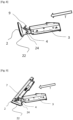
- the facade element 2 comprises a flap 22 of substantially flat shape, which has on its face oriented towards the support device 3 two tabs 24. These two tabs 24 extend substantially perpendicular to the flap 22, and has openings for receive the axis of rotation 4.
- This assembly with the axis 4 allows the rotation of the facade element 2 relative to the support device 3 around said axis of rotation 4.
- the facade element 2 is opposite the fixing plate 9 following the direction of translation of the support device 3 illustrated by the arrow T.
- the facade element 2 is folded down by pivoting under the force and contact with the shell 7 equipped with the portable electronic device during its installation on the fixing plate 9.
- the return means 6 of the facade element 2 towards the neutral position is a spring 6, connected on one side to the support device 3 and on the other to the facade element 2.
- the facade element 2 for example the flap 22, has a cavity in its thickness into which one of the ends of the spring 6 is inserted.
- the spring 6 comprises a helical part, used in torsion, disposed between a first end and a second end of the spring 6. The first end is held on the support device 3, while the second end is held on the facade element 2.
- the helical part is threaded onto the axis of rotation 4. The holding of the first end is achieved by example using a projecting stop installed on the support device 3, or by inserting the end of the spring into a slot or even a cavity.
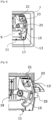
- THE figures 10 and 11 shows a particular embodiment of the return system 6 and its mounting on the support device 3.
- the lugs 24 are arranged so as to be on either side of the support device 3, that is to say that 'a part of the support device 3 is between the two legs 24.
- the axis of rotation 4 passes through the support device 3 and the two legs 24. It connects each of the legs 24 to the support device 3.
- the Figure 10 shows the support device 3 with the spring 6 and the facade element 2 in section along a plane perpendicular to the axis of rotation 4, plane passing between the two legs 24.
- the facade element 2 pivots under the support device 3, that is to say that when the support device 3 is installed in a vehicle passenger compartment, on the side of the support device 3 oriented towards the floor of the vehicle , therefore between the support device 3 and the vehicle floor.
- the support device 3 comprises a hollow 8 opening onto its underside, that is to say on its face disposed below, oriented towards the floor of the vehicle.
- the axis of rotation 4 opens into the hollow 8.
- the hollow 8 has on either side lateral faces, located substantially opposite the lugs 24 of the facade element 2, and which are crossed by the axis of rotation 4.
- the axis of rotation 4 can be made by two aligned sections crossing the lateral faces and each connected to one of the legs 24, or be a single element crossing right through the hollow 8 and s extending from one leg 24 to the other.
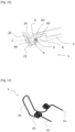
- the spring 6 comprises, as illustrated in Figure 11 , two helical parts 60, an intermediate part 64 located between the two helical parts 60, and two ends 62. That is to say that each helical part 60 has an end forming one of the ends 62 of the spring 6, and the two helical parts 60 are connected to each other by the intermediate part 64.
- the intermediate part 64 is linked to the facade element 2, the two ends 62 are connected to the support device 3, and each of the helical parts 60 is crossed by the axis of rotation. These two helical parts 60 therefore follow a helix of the same axis.
- the intermediate part 64 has a U shape, the branches of which are curved near the helical parts 60.
- This shape of the intermediate part 64 makes it possible to insert said intermediate part 64 into the cavity 20 of the flap 22, said cavity 20 opening onto face of the shutter 22 oriented towards the support device 3 when the facade element 2 is in the neutral position.
- the spring 6 therefore applies the restoring force on the facade element via its intermediate part 64, a force resulting in particular from the tensioning of the two helical parts 60.
- the spring 6 is produced for example, as illustrated in Figure 11 , by a single metal wire, such as a steel wire, folded and curved so as to produce the helical parts 60, the intermediate part 64 and the ends 62.
- the helical parts 60 are arranged inside the hollow 8, crossed by the axis of rotation 4 which thus maintains the spring 6.
- the ends 62 are also inside the hollow 8.
- the helical parts 60 and the ends 62 are supported against the lateral faces of the hollow 8.
- the width of the spring 6, that is to say its dimension in the direction of the axis of rotation 4, direction parallel to that of the direction of the axis of the parts helical 60, is for example greater than the width of the hollow 8, that is to say the spacing between the lateral faces of said hollow 9.
- These lateral faces may include projecting zones against which the ends 62 rest of the spring 6, in order to tension the spring 6 and thus create a force on the facade element 2 towards the neutral position.
- the projecting zones are for example steps made on the lateral faces of the hollow 9 against which the ends 62 of the spring 6 rest. These projecting zones form an element of the ends 62 of the spring 6.
Landscapes
- Engineering & Computer Science (AREA)
- Mechanical Engineering (AREA)
- Fittings On The Vehicle Exterior For Carrying Loads, And Devices For Holding Or Mounting Articles (AREA)
- Motor Or Generator Frames (AREA)
Claims (6)
- Anordnung (1) zur Befestigung eines tragbaren elektronischen Gerätes in einem Kraftfahrzeug, wobei die Anordnung (1) eine Haltevorrichtung (3) umfasst,- die Haltevorrichtung (3) eine Halteplatte (9) zur reversiblen Befestigung eines tragbaren elektronischen Gerätes umfasst,- und die Anordnung (1) umfasst ein Fassadenelement (2), das an der Trägervorrichtung (3) um eine Drehachse (4) zwischen einer neutralen Position, in der das Fassadenelement (2) der Platine (9) gegenüberliegt, und einer freigegebenen Position, in der das Fassadenelement (2) außerhalb der Platine (9) liegt, schwenkbar angebracht ist, um die Befestigung eines tragbaren elektronischen Gerätes an der Platine (9) zu ermöglichen, und ein Rückstellmittel (6) des Fassadenelements (2) in die neutrale Position, das Mittel Rückstelleinrichtung, bei der es sich um eine Feder (6) handelt, die sich einerseits auf der Tragvorrichtung (3) und andererseits auf dem Fassadenelement (2) abstützt, wobei das Fassadenelement (2) auf beiden Seiten der Tragvorrichtung (3) durch die Drehachse (4) an der Tragvorrichtung (3) gehalten ist, dadurch gekennzeichnet, dass die Feder zwei schraubenförmige Teile (60) und einen zwischen den beiden schraubenförmigen Teilen (60) angeordneten Zwischenabschnitt aufweist, wobei jeder dieser schraubenförmigen Teile (60) von der Drehachse (4) durchsetzt ist und jedes ein Ende (4) aufweist 62) mit der Trägereinrichtung (3) verbunden ist, wobei das Zwischenteil (64) mit dem Fassadenelement (2) verbunden ist.
- Anordnung nach Anspruch 1, bei der das Fassadenelement (2) eine Ausnehmung (20) aufweist, wobei sich der Zwischenabschnitt (64) der Feder (6) in der Ausnehmung (20) des Fassadenelements (2) befindet, wobei die Ausnehmung (20) an der Seite der Klappe (22) mündet, die der Stützvorrichtung (3) zugewandt ist, wenn sich das Fassadenelement (2) in der neutralen Position befindet.
- Anordnung nach einem der Ansprüche 1 bis 2, bei der die Haltevorrichtung (3) ein Halteelement aufweist, an dem sich jedes der Enden (62) der Feder (6) abstützt.
- 4/ Anordnung (1) nach einem der vorhergehenden Ansprüche, mit einer Schale (7) zur Aufnahme des tragbaren elektronischen Geräts, wobei die Schale (7) ein Gehäuse (11) aufweist, das zur Aufnahme der Befestigungsplatte (9) für die reversible Befestigung der Schale (7) an der Haltevorrichtung (3) ausgebildet ist.
- Anordnung (1) nach Anspruch 4, dadurch gekennzeichnet, dass die Befestigungsplatine (9) mindestens eine Kerbe (17) aufweist und dass die Schale (7) eine Befestigungsvorrichtung (13) mit mindestens einem Haken (15) aufweist, der zwischen einer Öffnungsposition und einer Verriegelungsposition bewegbar ist, um die Schale (7) durch Zusammenwirken zwischen dem Haken (15) und der Kerbe (17) an der Haltevorrichtung (3) reversibel zu befestigen; wobei vorzugsweise die Schale (7) mindestens ein Paar Haken (15) aufweist, die eine Backe und die Platine (9) bilden) mindestens ein Paar Kerben (17) aufweist.
- Fahrzeug mit einer Baugruppe (1) nach einem der vorhergehenden Ansprüche.
Applications Claiming Priority (3)
| Application Number | Priority Date | Filing Date | Title |
|---|---|---|---|
| FR2006820A FR3111858A1 (fr) | 2020-06-29 | 2020-06-29 | Ensemble pour la fixation d’un appareil électronique portatif dans un véhicule automobile |
| FR2007729A FR3111860B1 (fr) | 2020-06-29 | 2020-07-23 | Ensemble avec façade mobile pour la fixation d’un appareil électronique portatif dans un véhicule automobile |
| PCT/FR2021/051336 WO2022018367A1 (fr) | 2020-06-29 | 2021-07-16 | Ensemble avec façade mobile pour la fixation d'un appareil électronique portatif dans un véhicule automobile |
Publications (2)
| Publication Number | Publication Date |
|---|---|
| EP4185491A1 EP4185491A1 (de) | 2023-05-31 |
| EP4185491B1 true EP4185491B1 (de) | 2024-06-26 |
Family
ID=73642983
Family Applications (2)
| Application Number | Title | Priority Date | Filing Date |
|---|---|---|---|
| EP21740604.0A Active EP4172000B1 (de) | 2020-06-29 | 2021-06-22 | Anordnung zur befestigung eines tragbaren elektronischen geräts an einem kraftfahrzeug |
| EP21755521.8A Active EP4185491B1 (de) | 2020-06-29 | 2021-07-16 | Einheit mit beweglicher vorderseite zur befestigung einer tragbaren elektronischen vorrichtung in einem kraftfahrzeug |
Family Applications Before (1)
| Application Number | Title | Priority Date | Filing Date |
|---|---|---|---|
| EP21740604.0A Active EP4172000B1 (de) | 2020-06-29 | 2021-06-22 | Anordnung zur befestigung eines tragbaren elektronischen geräts an einem kraftfahrzeug |
Country Status (5)
| Country | Link |
|---|---|
| EP (2) | EP4172000B1 (de) |
| CN (2) | CN115734900A (de) |
| ES (1) | ES2983775T3 (de) |
| FR (2) | FR3111858A1 (de) |
| WO (2) | WO2022003272A1 (de) |
Family Cites Families (10)
| Publication number | Priority date | Publication date | Assignee | Title |
|---|---|---|---|---|
| GB1256705A (de) | 1968-04-24 | 1971-12-15 | ||
| CH498171A (de) | 1968-05-03 | 1970-10-31 | Ciba Geigy | Neue, flexibilisierte, härtbare Mischungen aus Polyepoxiden und Polyepoxid-Polyamin-Addukten |
| JP2008296637A (ja) * | 2007-05-29 | 2008-12-11 | Cellstar Kogyo Kk | 車載受信器用支持具 |
| CN101734204A (zh) * | 2008-11-21 | 2010-06-16 | 昆达电脑科技(昆山)有限公司 | 承载电子设备的装置 |
| DE102014004955A1 (de) * | 2014-04-05 | 2015-10-08 | GM Global Technology Operations LLC (n. d. Gesetzen des Staates Delaware) | Vorrichtung zum Halten eines Smartphones in einem Fahrzeuginnenraum |
| FR3021931B1 (fr) * | 2014-06-04 | 2016-07-01 | Renault Sa | Planche de bord de vehicule automobile comprenant un support de tablette |
| JP6753692B2 (ja) * | 2016-05-13 | 2020-09-09 | 株式会社パイオラックス | フラップ弁装置 |
| FR3056504B1 (fr) | 2016-09-27 | 2019-07-05 | Renault S.A.S | Dispositif de support pour appareil electronique portatif |
| GB2563211B (en) * | 2017-06-05 | 2019-09-04 | Ford Global Tech Llc | A portable electronic device support assembly |
| DE202018103407U1 (de) * | 2018-06-18 | 2018-06-26 | Wen-Feng Tsai | Mobilgerätehalter für die Montage im Fahrzeug |
-
2020
- 2020-06-29 FR FR2006820A patent/FR3111858A1/fr not_active Withdrawn
- 2020-07-23 FR FR2007729A patent/FR3111860B1/fr active Active
-
2021
- 2021-06-22 EP EP21740604.0A patent/EP4172000B1/de active Active
- 2021-06-22 CN CN202180046572.1A patent/CN115734900A/zh active Pending
- 2021-06-22 WO PCT/FR2021/051138 patent/WO2022003272A1/fr not_active Ceased
- 2021-07-16 CN CN202180059903.5A patent/CN116137846A/zh active Pending
- 2021-07-16 WO PCT/FR2021/051336 patent/WO2022018367A1/fr not_active Ceased
- 2021-07-16 ES ES21755521T patent/ES2983775T3/es active Active
- 2021-07-16 EP EP21755521.8A patent/EP4185491B1/de active Active
Also Published As
| Publication number | Publication date |
|---|---|
| FR3111858A1 (fr) | 2021-12-31 |
| WO2022018367A1 (fr) | 2022-01-27 |
| EP4172000A1 (de) | 2023-05-03 |
| FR3111860A1 (fr) | 2021-12-31 |
| ES2983775T3 (es) | 2024-10-24 |
| CN115734900A (zh) | 2023-03-03 |
| CN116137846A (zh) | 2023-05-19 |
| EP4172000B1 (de) | 2024-05-29 |
| EP4185491A1 (de) | 2023-05-31 |
| FR3111860B1 (fr) | 2024-05-10 |
| WO2022003272A1 (fr) | 2022-01-06 |
Similar Documents
| Publication | Publication Date | Title |
|---|---|---|
| FR2548106A1 (fr) | Siege auxiliaire pour vehicules | |
| EP1222090A1 (de) | Auf einem kraftfahrzeug anzubringende kindersicherungseinrichtung | |
| FR2989651A1 (fr) | Tablette de siege formant support d'ecran tactile | |
| FR2811273A1 (fr) | Dispositif de liaison d'un siege amovible et a assise basculante avec le plancher d'un vehicule automobile | |
| FR2946583A1 (fr) | Siege auto pour enfant, destine a equiper un siege de vehicule | |
| EP3381753B1 (de) | Schwenkbare gurtschnalle | |
| EP4185491B1 (de) | Einheit mit beweglicher vorderseite zur befestigung einer tragbaren elektronischen vorrichtung in einem kraftfahrzeug | |
| EP2911913B1 (de) | Vorrichtung zum einstellen der neigung einer bodenklappe des kofferraumbodens bei einem kraftfahrzeug sowie ein kraftfahrzeug mit genannter einstellvorrichtung | |
| FR2810929A1 (fr) | Dispositif d'assise pour vehicule | |
| EP2085266B1 (de) | Innerer Dachgepäckträger | |
| FR2796344A1 (fr) | Mecanisme d'ancrage et d'articulation, notamment pour un siege arriere d'un vehicule automobile | |
| EP0718145A1 (de) | Ruhesitzschale für Kleinkinder | |
| FR2957563A1 (fr) | Siege auto muni d'une jambe de force a semelle a inclinaison reglable | |
| EP0543706A1 (de) | Vorrichtung zum automatischen Kuppeln einer Sicherheitsgurtverankerung mit dem Boden eines Fahrzeuges | |
| EP3210822A1 (de) | Vorrichtung zum einhaken eines fahrzeugsitzes ohne drehmoment in der halterung im falle einer kollision | |
| FR2834943A1 (fr) | Dispositif de fixation d'un siege sur un plancher de vehicule, et siege ainsi que vehicule comprenant un tel dispositif de fixation | |
| FR3160656A1 (fr) | Dispositif d’accrochage de boucle de ceinture de sécurité | |
| EP3532341B1 (de) | Modularer sitz für ein kraftfahrzeug | |
| FR2859953A1 (fr) | Siege de vehicule et vehicule comportant un tel siege. | |
| FR2706409A1 (fr) | Dispositif d'accrochage réversible d'un siège sur un plancher de véhicule automobile. | |
| FR3160143A1 (fr) | Dispositif de séparation pour réaliser une séparation entre la zone de chargement et un habitacle d’un véhicule | |
| FR2804914A1 (fr) | Siege de vehicule dote d'une traverse de securite | |
| FR3064570B1 (fr) | Brin-boucle de ceinture de securite | |
| FR3071785B1 (fr) | Structure de siege de vehicule automobile dotee d’une agrafe de maintien d’un carter de recouvrement. | |
| FR2908702A1 (fr) | Agencement de porte-recipient pour une tablette de vehicule automobile |
Legal Events
| Date | Code | Title | Description |
|---|---|---|---|
| STAA | Information on the status of an ep patent application or granted ep patent |
Free format text: STATUS: UNKNOWN |
|
| STAA | Information on the status of an ep patent application or granted ep patent |
Free format text: STATUS: THE INTERNATIONAL PUBLICATION HAS BEEN MADE |
|
| PUAI | Public reference made under article 153(3) epc to a published international application that has entered the european phase |
Free format text: ORIGINAL CODE: 0009012 |
|
| STAA | Information on the status of an ep patent application or granted ep patent |
Free format text: STATUS: REQUEST FOR EXAMINATION WAS MADE |
|
| 17P | Request for examination filed |
Effective date: 20230112 |
|
| AK | Designated contracting states |
Kind code of ref document: A1 Designated state(s): AL AT BE BG CH CY CZ DE DK EE ES FI FR GB GR HR HU IE IS IT LI LT LU LV MC MK MT NL NO PL PT RO RS SE SI SK SM TR |
|
| DAV | Request for validation of the european patent (deleted) | ||
| DAX | Request for extension of the european patent (deleted) | ||
| STAA | Information on the status of an ep patent application or granted ep patent |
Free format text: STATUS: EXAMINATION IS IN PROGRESS |
|
| 17Q | First examination report despatched |
Effective date: 20231102 |
|
| RAP3 | Party data changed (applicant data changed or rights of an application transferred) |
Owner name: STELLANTIS AUTO SAS |
|
| GRAP | Despatch of communication of intention to grant a patent |
Free format text: ORIGINAL CODE: EPIDOSNIGR1 |
|
| STAA | Information on the status of an ep patent application or granted ep patent |
Free format text: STATUS: GRANT OF PATENT IS INTENDED |
|
| INTG | Intention to grant announced |
Effective date: 20240212 |
|
| GRAS | Grant fee paid |
Free format text: ORIGINAL CODE: EPIDOSNIGR3 |
|
| GRAA | (expected) grant |
Free format text: ORIGINAL CODE: 0009210 |
|
| STAA | Information on the status of an ep patent application or granted ep patent |
Free format text: STATUS: THE PATENT HAS BEEN GRANTED |
|
| AK | Designated contracting states |
Kind code of ref document: B1 Designated state(s): AL AT BE BG CH CY CZ DE DK EE ES FI FR GB GR HR HU IE IS IT LI LT LU LV MC MK MT NL NO PL PT RO RS SE SI SK SM TR |
|
| REG | Reference to a national code |
Ref country code: GB Ref legal event code: FG4D Free format text: NOT ENGLISH |
|
| REG | Reference to a national code |
Ref country code: CH Ref legal event code: EP |
|
| REG | Reference to a national code |
Ref country code: ES Ref legal event code: GC2A Effective date: 20240710 |
|
| REG | Reference to a national code |
Ref country code: DE Ref legal event code: R096 Ref document number: 602021014908 Country of ref document: DE |
|
| REG | Reference to a national code |
Ref country code: GB Ref legal event code: 746 Effective date: 20240724 |
|
| PG25 | Lapsed in a contracting state [announced via postgrant information from national office to epo] |
Ref country code: BG Free format text: LAPSE BECAUSE OF FAILURE TO SUBMIT A TRANSLATION OF THE DESCRIPTION OR TO PAY THE FEE WITHIN THE PRESCRIBED TIME-LIMIT Effective date: 20240626 |
|
| PG25 | Lapsed in a contracting state [announced via postgrant information from national office to epo] |
Ref country code: FI Free format text: LAPSE BECAUSE OF FAILURE TO SUBMIT A TRANSLATION OF THE DESCRIPTION OR TO PAY THE FEE WITHIN THE PRESCRIBED TIME-LIMIT Effective date: 20240626 Ref country code: HR Free format text: LAPSE BECAUSE OF FAILURE TO SUBMIT A TRANSLATION OF THE DESCRIPTION OR TO PAY THE FEE WITHIN THE PRESCRIBED TIME-LIMIT Effective date: 20240626 |
|
| REG | Reference to a national code |
Ref country code: LT Ref legal event code: MG9D |
|
| PG25 | Lapsed in a contracting state [announced via postgrant information from national office to epo] |
Ref country code: GR Free format text: LAPSE BECAUSE OF FAILURE TO SUBMIT A TRANSLATION OF THE DESCRIPTION OR TO PAY THE FEE WITHIN THE PRESCRIBED TIME-LIMIT Effective date: 20240927 |
|
| REG | Reference to a national code |
Ref country code: DE Ref legal event code: R084 Ref document number: 602021014908 Country of ref document: DE |
|
| REG | Reference to a national code |
Ref country code: ES Ref legal event code: FG2A Ref document number: 2983775 Country of ref document: ES Kind code of ref document: T3 Effective date: 20241024 |
|
| PG25 | Lapsed in a contracting state [announced via postgrant information from national office to epo] |
Ref country code: LV Free format text: LAPSE BECAUSE OF FAILURE TO SUBMIT A TRANSLATION OF THE DESCRIPTION OR TO PAY THE FEE WITHIN THE PRESCRIBED TIME-LIMIT Effective date: 20240626 |
|
| REG | Reference to a national code |
Ref country code: NL Ref legal event code: MP Effective date: 20240626 |
|
| PG25 | Lapsed in a contracting state [announced via postgrant information from national office to epo] |
Ref country code: NO Free format text: LAPSE BECAUSE OF FAILURE TO SUBMIT A TRANSLATION OF THE DESCRIPTION OR TO PAY THE FEE WITHIN THE PRESCRIBED TIME-LIMIT Effective date: 20240926 Ref country code: LV Free format text: LAPSE BECAUSE OF FAILURE TO SUBMIT A TRANSLATION OF THE DESCRIPTION OR TO PAY THE FEE WITHIN THE PRESCRIBED TIME-LIMIT Effective date: 20240626 Ref country code: HR Free format text: LAPSE BECAUSE OF FAILURE TO SUBMIT A TRANSLATION OF THE DESCRIPTION OR TO PAY THE FEE WITHIN THE PRESCRIBED TIME-LIMIT Effective date: 20240626 Ref country code: GR Free format text: LAPSE BECAUSE OF FAILURE TO SUBMIT A TRANSLATION OF THE DESCRIPTION OR TO PAY THE FEE WITHIN THE PRESCRIBED TIME-LIMIT Effective date: 20240927 Ref country code: FI Free format text: LAPSE BECAUSE OF FAILURE TO SUBMIT A TRANSLATION OF THE DESCRIPTION OR TO PAY THE FEE WITHIN THE PRESCRIBED TIME-LIMIT Effective date: 20240626 Ref country code: BG Free format text: LAPSE BECAUSE OF FAILURE TO SUBMIT A TRANSLATION OF THE DESCRIPTION OR TO PAY THE FEE WITHIN THE PRESCRIBED TIME-LIMIT Effective date: 20240626 Ref country code: RS Free format text: LAPSE BECAUSE OF FAILURE TO SUBMIT A TRANSLATION OF THE DESCRIPTION OR TO PAY THE FEE WITHIN THE PRESCRIBED TIME-LIMIT Effective date: 20240926 |
|
| PG25 | Lapsed in a contracting state [announced via postgrant information from national office to epo] |
Ref country code: NL Free format text: LAPSE BECAUSE OF FAILURE TO SUBMIT A TRANSLATION OF THE DESCRIPTION OR TO PAY THE FEE WITHIN THE PRESCRIBED TIME-LIMIT Effective date: 20240626 |
|
| REG | Reference to a national code |
Ref country code: AT Ref legal event code: MK05 Ref document number: 1697453 Country of ref document: AT Kind code of ref document: T Effective date: 20240626 |
|
| PG25 | Lapsed in a contracting state [announced via postgrant information from national office to epo] |
Ref country code: NL Free format text: LAPSE BECAUSE OF FAILURE TO SUBMIT A TRANSLATION OF THE DESCRIPTION OR TO PAY THE FEE WITHIN THE PRESCRIBED TIME-LIMIT Effective date: 20240626 |
|
| PG25 | Lapsed in a contracting state [announced via postgrant information from national office to epo] |
Ref country code: PT Free format text: LAPSE BECAUSE OF FAILURE TO SUBMIT A TRANSLATION OF THE DESCRIPTION OR TO PAY THE FEE WITHIN THE PRESCRIBED TIME-LIMIT Effective date: 20241028 |
|
| PG25 | Lapsed in a contracting state [announced via postgrant information from national office to epo] |
Ref country code: PT Free format text: LAPSE BECAUSE OF FAILURE TO SUBMIT A TRANSLATION OF THE DESCRIPTION OR TO PAY THE FEE WITHIN THE PRESCRIBED TIME-LIMIT Effective date: 20241028 |
|
| PG25 | Lapsed in a contracting state [announced via postgrant information from national office to epo] |
Ref country code: PL Free format text: LAPSE BECAUSE OF FAILURE TO SUBMIT A TRANSLATION OF THE DESCRIPTION OR TO PAY THE FEE WITHIN THE PRESCRIBED TIME-LIMIT Effective date: 20240626 |
|
| PG25 | Lapsed in a contracting state [announced via postgrant information from national office to epo] |
Ref country code: EE Free format text: LAPSE BECAUSE OF FAILURE TO SUBMIT A TRANSLATION OF THE DESCRIPTION OR TO PAY THE FEE WITHIN THE PRESCRIBED TIME-LIMIT Effective date: 20240626 |
|
| PG25 | Lapsed in a contracting state [announced via postgrant information from national office to epo] |
Ref country code: IS Free format text: LAPSE BECAUSE OF FAILURE TO SUBMIT A TRANSLATION OF THE DESCRIPTION OR TO PAY THE FEE WITHIN THE PRESCRIBED TIME-LIMIT Effective date: 20241026 Ref country code: AT Free format text: LAPSE BECAUSE OF FAILURE TO SUBMIT A TRANSLATION OF THE DESCRIPTION OR TO PAY THE FEE WITHIN THE PRESCRIBED TIME-LIMIT Effective date: 20240626 |
|
| PG25 | Lapsed in a contracting state [announced via postgrant information from national office to epo] |
Ref country code: CZ Free format text: LAPSE BECAUSE OF FAILURE TO SUBMIT A TRANSLATION OF THE DESCRIPTION OR TO PAY THE FEE WITHIN THE PRESCRIBED TIME-LIMIT Effective date: 20240626 |
|
| PG25 | Lapsed in a contracting state [announced via postgrant information from national office to epo] |
Ref country code: RO Free format text: LAPSE BECAUSE OF FAILURE TO SUBMIT A TRANSLATION OF THE DESCRIPTION OR TO PAY THE FEE WITHIN THE PRESCRIBED TIME-LIMIT Effective date: 20240626 Ref country code: SK Free format text: LAPSE BECAUSE OF FAILURE TO SUBMIT A TRANSLATION OF THE DESCRIPTION OR TO PAY THE FEE WITHIN THE PRESCRIBED TIME-LIMIT Effective date: 20240626 |
|
| PG25 | Lapsed in a contracting state [announced via postgrant information from national office to epo] |
Ref country code: SM Free format text: LAPSE BECAUSE OF FAILURE TO SUBMIT A TRANSLATION OF THE DESCRIPTION OR TO PAY THE FEE WITHIN THE PRESCRIBED TIME-LIMIT Effective date: 20240626 |
|
| PG25 | Lapsed in a contracting state [announced via postgrant information from national office to epo] |
Ref country code: SM Free format text: LAPSE BECAUSE OF FAILURE TO SUBMIT A TRANSLATION OF THE DESCRIPTION OR TO PAY THE FEE WITHIN THE PRESCRIBED TIME-LIMIT Effective date: 20240626 Ref country code: SK Free format text: LAPSE BECAUSE OF FAILURE TO SUBMIT A TRANSLATION OF THE DESCRIPTION OR TO PAY THE FEE WITHIN THE PRESCRIBED TIME-LIMIT Effective date: 20240626 Ref country code: RO Free format text: LAPSE BECAUSE OF FAILURE TO SUBMIT A TRANSLATION OF THE DESCRIPTION OR TO PAY THE FEE WITHIN THE PRESCRIBED TIME-LIMIT Effective date: 20240626 Ref country code: PL Free format text: LAPSE BECAUSE OF FAILURE TO SUBMIT A TRANSLATION OF THE DESCRIPTION OR TO PAY THE FEE WITHIN THE PRESCRIBED TIME-LIMIT Effective date: 20240626 Ref country code: IS Free format text: LAPSE BECAUSE OF FAILURE TO SUBMIT A TRANSLATION OF THE DESCRIPTION OR TO PAY THE FEE WITHIN THE PRESCRIBED TIME-LIMIT Effective date: 20241026 Ref country code: EE Free format text: LAPSE BECAUSE OF FAILURE TO SUBMIT A TRANSLATION OF THE DESCRIPTION OR TO PAY THE FEE WITHIN THE PRESCRIBED TIME-LIMIT Effective date: 20240626 Ref country code: CZ Free format text: LAPSE BECAUSE OF FAILURE TO SUBMIT A TRANSLATION OF THE DESCRIPTION OR TO PAY THE FEE WITHIN THE PRESCRIBED TIME-LIMIT Effective date: 20240626 Ref country code: AT Free format text: LAPSE BECAUSE OF FAILURE TO SUBMIT A TRANSLATION OF THE DESCRIPTION OR TO PAY THE FEE WITHIN THE PRESCRIBED TIME-LIMIT Effective date: 20240626 |
|
| PG25 | Lapsed in a contracting state [announced via postgrant information from national office to epo] |
Ref country code: IT Free format text: LAPSE BECAUSE OF FAILURE TO SUBMIT A TRANSLATION OF THE DESCRIPTION OR TO PAY THE FEE WITHIN THE PRESCRIBED TIME-LIMIT Effective date: 20240626 |
|
| REG | Reference to a national code |
Ref country code: CH Ref legal event code: PL |
|
| PG25 | Lapsed in a contracting state [announced via postgrant information from national office to epo] |
Ref country code: LU Free format text: LAPSE BECAUSE OF NON-PAYMENT OF DUE FEES Effective date: 20240716 |
|
| PG25 | Lapsed in a contracting state [announced via postgrant information from national office to epo] |
Ref country code: MC Free format text: LAPSE BECAUSE OF FAILURE TO SUBMIT A TRANSLATION OF THE DESCRIPTION OR TO PAY THE FEE WITHIN THE PRESCRIBED TIME-LIMIT Effective date: 20240626 |
|
| REG | Reference to a national code |
Ref country code: DE Ref legal event code: R097 Ref document number: 602021014908 Country of ref document: DE |
|
| PG25 | Lapsed in a contracting state [announced via postgrant information from national office to epo] |
Ref country code: MC Free format text: LAPSE BECAUSE OF FAILURE TO SUBMIT A TRANSLATION OF THE DESCRIPTION OR TO PAY THE FEE WITHIN THE PRESCRIBED TIME-LIMIT Effective date: 20240626 Ref country code: LU Free format text: LAPSE BECAUSE OF NON-PAYMENT OF DUE FEES Effective date: 20240716 |
|
| PG25 | Lapsed in a contracting state [announced via postgrant information from national office to epo] |
Ref country code: DK Free format text: LAPSE BECAUSE OF FAILURE TO SUBMIT A TRANSLATION OF THE DESCRIPTION OR TO PAY THE FEE WITHIN THE PRESCRIBED TIME-LIMIT Effective date: 20240626 |
|
| PG25 | Lapsed in a contracting state [announced via postgrant information from national office to epo] |
Ref country code: CH Free format text: LAPSE BECAUSE OF NON-PAYMENT OF DUE FEES Effective date: 20240731 Ref country code: BE Free format text: LAPSE BECAUSE OF NON-PAYMENT OF DUE FEES Effective date: 20240731 |
|
| PLBE | No opposition filed within time limit |
Free format text: ORIGINAL CODE: 0009261 |
|
| STAA | Information on the status of an ep patent application or granted ep patent |
Free format text: STATUS: NO OPPOSITION FILED WITHIN TIME LIMIT |
|
| 26N | No opposition filed |
Effective date: 20250327 |
|
| REG | Reference to a national code |
Ref country code: BE Ref legal event code: MM Effective date: 20240731 |
|
| PGFP | Annual fee paid to national office [announced via postgrant information from national office to epo] |
Ref country code: GB Payment date: 20250619 Year of fee payment: 5 |
|
| PGFP | Annual fee paid to national office [announced via postgrant information from national office to epo] |
Ref country code: FR Payment date: 20250619 Year of fee payment: 5 |
|
| PG25 | Lapsed in a contracting state [announced via postgrant information from national office to epo] |
Ref country code: IE Free format text: LAPSE BECAUSE OF NON-PAYMENT OF DUE FEES Effective date: 20240716 |
|
| PG25 | Lapsed in a contracting state [announced via postgrant information from national office to epo] |
Ref country code: SE Free format text: LAPSE BECAUSE OF FAILURE TO SUBMIT A TRANSLATION OF THE DESCRIPTION OR TO PAY THE FEE WITHIN THE PRESCRIBED TIME-LIMIT Effective date: 20240626 |
|
| PGFP | Annual fee paid to national office [announced via postgrant information from national office to epo] |
Ref country code: ES Payment date: 20250801 Year of fee payment: 5 |
|
| PGFP | Annual fee paid to national office [announced via postgrant information from national office to epo] |
Ref country code: DE Payment date: 20250620 Year of fee payment: 5 |
|
| PG25 | Lapsed in a contracting state [announced via postgrant information from national office to epo] |
Ref country code: CY Free format text: LAPSE BECAUSE OF FAILURE TO SUBMIT A TRANSLATION OF THE DESCRIPTION OR TO PAY THE FEE WITHIN THE PRESCRIBED TIME-LIMIT; INVALID AB INITIO Effective date: 20210716 |
|
| PG25 | Lapsed in a contracting state [announced via postgrant information from national office to epo] |
Ref country code: HU Free format text: LAPSE BECAUSE OF FAILURE TO SUBMIT A TRANSLATION OF THE DESCRIPTION OR TO PAY THE FEE WITHIN THE PRESCRIBED TIME-LIMIT; INVALID AB INITIO Effective date: 20210716 |