EP4186605B1 - Kühlrollenbahn zur verbesserung der kühlgleichmässigkeit einer spinnspule und verfahren dazu - Google Patents
Kühlrollenbahn zur verbesserung der kühlgleichmässigkeit einer spinnspule und verfahren dazu Download PDFInfo
- Publication number
- EP4186605B1 EP4186605B1 EP21938790.9A EP21938790A EP4186605B1 EP 4186605 B1 EP4186605 B1 EP 4186605B1 EP 21938790 A EP21938790 A EP 21938790A EP 4186605 B1 EP4186605 B1 EP 4186605B1
- Authority
- EP
- European Patent Office
- Prior art keywords
- roller way
- coil
- way body
- cooling
- fixed seat
- Prior art date
- Legal status (The legal status is an assumption and is not a legal conclusion. Google has not performed a legal analysis and makes no representation as to the accuracy of the status listed.)
- Active
Links
Images

Classifications
-
- B—PERFORMING OPERATIONS; TRANSPORTING
- B21—MECHANICAL METAL-WORKING WITHOUT ESSENTIALLY REMOVING MATERIAL; PUNCHING METAL
- B21B—ROLLING OF METAL
- B21B45/00—Devices for surface or other treatment of work, specially combined with or arranged in, or specially adapted for use in connection with, metal-rolling mills
- B21B45/02—Devices for surface or other treatment of work, specially combined with or arranged in, or specially adapted for use in connection with, metal-rolling mills for lubricating, cooling, or cleaning
- B21B45/0203—Cooling
-
- C—CHEMISTRY; METALLURGY
- C21—METALLURGY OF IRON
- C21D—MODIFYING THE PHYSICAL STRUCTURE OF FERROUS METALS; GENERAL DEVICES FOR HEAT TREATMENT OF FERROUS OR NON-FERROUS METALS OR ALLOYS; MAKING METAL MALLEABLE, e.g. BY DECARBURISATION OR TEMPERING
- C21D9/00—Heat treatment, e.g. annealing, hardening, quenching or tempering, adapted for particular articles; Furnaces therefor
- C21D9/52—Heat treatment, e.g. annealing, hardening, quenching or tempering, adapted for particular articles; Furnaces therefor for wires; for strips ; for rods of unlimited length
- C21D9/54—Furnaces for treating strips or wire
- C21D9/56—Continuous furnaces for strip or wire
- C21D9/573—Continuous furnaces for strip or wire with cooling
- C21D9/5735—Details
- C21D9/5737—Rolls; Drums; Roll arrangements
-
- B—PERFORMING OPERATIONS; TRANSPORTING
- B21—MECHANICAL METAL-WORKING WITHOUT ESSENTIALLY REMOVING MATERIAL; PUNCHING METAL
- B21C—MANUFACTURE OF METAL SHEETS, WIRE, RODS, TUBES, PROFILES OR LIKE SEMI-MANUFACTURED PRODUCTS OTHERWISE THAN BY ROLLING; AUXILIARY OPERATIONS USED IN CONNECTION WITH METAL-WORKING WITHOUT ESSENTIALLY REMOVING MATERIAL
- B21C47/00—Winding-up, coiling or winding-off metal wire, metal band or other flexible metal material characterised by features relevant to metal processing only
- B21C47/02—Winding-up or coiling
- B21C47/08—Winding-up or coiling without making use of a reel or drum, the first turn being formed by a stationary guide
-
- B—PERFORMING OPERATIONS; TRANSPORTING
- B21—MECHANICAL METAL-WORKING WITHOUT ESSENTIALLY REMOVING MATERIAL; PUNCHING METAL
- B21C—MANUFACTURE OF METAL SHEETS, WIRE, RODS, TUBES, PROFILES OR LIKE SEMI-MANUFACTURED PRODUCTS OTHERWISE THAN BY ROLLING; AUXILIARY OPERATIONS USED IN CONNECTION WITH METAL-WORKING WITHOUT ESSENTIALLY REMOVING MATERIAL
- B21C47/00—Winding-up, coiling or winding-off metal wire, metal band or other flexible metal material characterised by features relevant to metal processing only
- B21C47/02—Winding-up or coiling
- B21C47/10—Winding-up or coiling by means of a moving guide
-
- B—PERFORMING OPERATIONS; TRANSPORTING
- B21—MECHANICAL METAL-WORKING WITHOUT ESSENTIALLY REMOVING MATERIAL; PUNCHING METAL
- B21C—MANUFACTURE OF METAL SHEETS, WIRE, RODS, TUBES, PROFILES OR LIKE SEMI-MANUFACTURED PRODUCTS OTHERWISE THAN BY ROLLING; AUXILIARY OPERATIONS USED IN CONNECTION WITH METAL-WORKING WITHOUT ESSENTIALLY REMOVING MATERIAL
- B21C47/00—Winding-up, coiling or winding-off metal wire, metal band or other flexible metal material characterised by features relevant to metal processing only
- B21C47/02—Winding-up or coiling
- B21C47/10—Winding-up or coiling by means of a moving guide
- B21C47/14—Winding-up or coiling by means of a moving guide by means of a rotating guide, e.g. laying the material around a stationary reel or drum
- B21C47/146—Controlling or influencing the laying pattern of the coils
-
- B—PERFORMING OPERATIONS; TRANSPORTING
- B21—MECHANICAL METAL-WORKING WITHOUT ESSENTIALLY REMOVING MATERIAL; PUNCHING METAL
- B21C—MANUFACTURE OF METAL SHEETS, WIRE, RODS, TUBES, PROFILES OR LIKE SEMI-MANUFACTURED PRODUCTS OTHERWISE THAN BY ROLLING; AUXILIARY OPERATIONS USED IN CONNECTION WITH METAL-WORKING WITHOUT ESSENTIALLY REMOVING MATERIAL
- B21C47/00—Winding-up, coiling or winding-off metal wire, metal band or other flexible metal material characterised by features relevant to metal processing only
- B21C47/26—Special arrangements with regard to simultaneous or subsequent treatment of the material
- B21C47/262—Treatment of a wire, while in the form of overlapping non-concentric rings
-
- C—CHEMISTRY; METALLURGY
- C21—METALLURGY OF IRON
- C21D—MODIFYING THE PHYSICAL STRUCTURE OF FERROUS METALS; GENERAL DEVICES FOR HEAT TREATMENT OF FERROUS OR NON-FERROUS METALS OR ALLOYS; MAKING METAL MALLEABLE, e.g. BY DECARBURISATION OR TEMPERING
- C21D9/00—Heat treatment, e.g. annealing, hardening, quenching or tempering, adapted for particular articles; Furnaces therefor
- C21D9/52—Heat treatment, e.g. annealing, hardening, quenching or tempering, adapted for particular articles; Furnaces therefor for wires; for strips ; for rods of unlimited length
- C21D9/54—Furnaces for treating strips or wire
- C21D9/56—Continuous furnaces for strip or wire
- C21D9/573—Continuous furnaces for strip or wire with cooling
- C21D9/5732—Continuous furnaces for strip or wire with cooling of wires; of rods
-
- B—PERFORMING OPERATIONS; TRANSPORTING
- B21—MECHANICAL METAL-WORKING WITHOUT ESSENTIALLY REMOVING MATERIAL; PUNCHING METAL
- B21B—ROLLING OF METAL
- B21B45/00—Devices for surface or other treatment of work, specially combined with or arranged in, or specially adapted for use in connection with, metal-rolling mills
- B21B45/02—Devices for surface or other treatment of work, specially combined with or arranged in, or specially adapted for use in connection with, metal-rolling mills for lubricating, cooling, or cleaning
- B21B45/0203—Cooling
- B21B45/0209—Cooling devices, e.g. using gaseous coolants
- B21B2045/0212—Cooling devices, e.g. using gaseous coolants using gaseous coolants
Definitions
- the present disclosure relates to the technical field of wire production equipment, in particular to a cooling roller way for improving the cooling uniformity of a spinning coil as specified in any of claims 1-3 and use of the cooling roller way as specified by claim 4.
- the coils are distributed in a continuous circle on the air-cooling roller way body, so that the stacking thickness of overlapping points is large at both sides and the stacking thickness is small in the middle, the stacking thickness of the whole uncoiled circle is non-uniform, and the temperature at the position of the edge overlapping points fluctuates greatly, which will not only lead to non-uniform heating of the overlapping points, but also affect the performance of the finished wire products in the same coil.
- PTL1 ( BE 789 039 A ) describes an apparatus and a method of cooling wire in a wire-forming machine comprises blowing air diagonally from above and below and from the sides laterally to cool the wire.
- PTL2 JP H06 19907 U 15 describes a uniform quenching apparatus and method for a hot rolled wire rod.
- PTL3 ( EP 0 384 010 A1 ) describes a method for transporting hot-rolled wire rod and an apparatus therefore.
- the technical problem to be solved by the present disclosure is as follows.
- the present disclosure provides a cooling roller way for improving the cooling uniformity of a spinning coil as specified in any of claims 1-3and use of the cooling roller way as specified by claim 4in order to overcome the problems in the prior art that the coils are distributed in a continuous circle on the roller way body, so that the stacking thickness of overlapping points is large at both sides and the stacking thickness is small in the middle, the overlapping points are non-uniformly heated, and the performance of the finished coils is degraded.
- a cooling roller way for improving the cooling uniformity of a spinning coil comprises a roller way body and several guiding mechanisms installed at both sides of the roller way body, wherein the guiding mechanisms at both sides of the roller way body are staggered, the roller way body is used to transport a coil, and the guiding mechanisms are used to change the running trajectory of the coil, so that overlapping points of the coil are uniformly distributed.
- the design of the guiding mechanisms on the roller way body can change the running trajectory of the wire, stagger the overlapping points with a larger stacking thickness in order, reduce the cooling non-uniformity, improve the organizational structure of the wire, make the temperature fluctuation of the overlapping points on the edge of the air-cooling roller way body achieve an ideal effect, reduce the performance of the coils in the same circle, and realize the homogenization of the coiling performance of the wire.
- the guiding mechanism comprises a fixed seat and a guide wheel
- the guide wheel is adjustable in position and is installed on the fixed seat
- the position adjustment direction of the guide wheel is staggered with the transmission direction of the roller way body.
- the fixed seat is adjustable in position and is installed on the roller way body, and the adjustment direction of the fixed seat is parallel to the transmission direction of the roller way body.
- a bracket is fixedly connected to the fixed seat, the bracket is erected on the roller way body, a base is fixedly connected to the bracket, and the base is located outside the roller way body.
- the base plays the role of increasing the counterweight, thus improving the stability of the guiding mechanism after being erected.
- the fixed seat is provided with a notch for the guide wheel to move
- the top surface of the fixed seat is provided with a supporting arm and two positioning plates
- the supporting arm and the notch are both located between the two positioning plates
- the positioning plate is provided with an adjusting hole extending to the center line of the roller way body
- a fixed screw is provided in the adjusting hole
- a rod part of the fixed screw is in threaded connection with the supporting arm
- the bottom surface of the supporting arm is provided with an axle
- the guide wheel and the axle are rotatably connected and axially fixed.
- guide plates are provided at both sides of the fixed seat.
- the guide plates additionally provided at both sides can effectively prevent the head and tail of the wire from entering the gap between the guide wheel and the inner side of the roller way body and avoid production accidents such as inverted insertion and a large number of crawling.
- the use comprises the following steps: according to the rolling specifications of a coil, adjusting the distance between two adjacent guide wheels at the same side of the roller way body or/and adjusting the length of the guide wheels extending to the center of the roller way body, so that the guide wheel is in contact with the coil so as to change the running trajectory of the coil, and finally the running trajectory is S-shaped, so that the overlapping points of the coil are staggered in order.
- the present disclosure has the following beneficial effects.
- the present disclosure provides a cooling roller way for improving the cooling uniformity of a spinning coil as specified in any of claims 1-3 and use of the cooling roller wayas specified by claim 4.
- the design of the guiding mechanisms on the roller way body can change the running trajectory of the wire, stagger the overlapping points with a larger stacking thickness in order, reduce the cooling non-uniformity, and improve the organizational structure of the wire.
- the temperature fluctuation of the overlapping points on the edge of the air-cooling roller way body achieves an ideal effect, the performance of the coils in the same circle is reduced, and the homogenization of the coiling performance of the wire is realized.
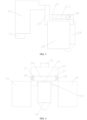
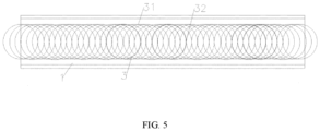
- roller way body 1, roller way body, 2, guiding mechanism, 21, base, 22, bracket, 23, fixed seat, 231, notch, 24, supporting arm, 25, axle, 26, guide wheel, 27, positioning plate, 271, adjusting hole, 28, fixed screw, 29, guide plate, 3, coil, 31, overlapping point, 32, non-overlapping point
- FIG. 1 is a structural schematic diagram of the present disclosure.
- a cooling roller way for improving the cooling uniformity of a spinning coil comprises a roller way body 1 and several guiding mechanisms 2 installed at both sides of the roller way body 1.
- the guiding mechanisms 2 at both sides of the roller way body 1 are staggered.
- the roller way body 1 is used to transport a coil 3.
- the guiding mechanisms 2 are used to change the running trajectory of the coil 3, so that overlapping points 31 of the coil 3 are uniformly distributed.
- the design of the guiding mechanisms 2 on the roller way body 1 can change the running trajectory of the wire, stagger the overlapping points with a larger stacking thickness in order, reduce the cooling non-uniformity, improve the organizational structure of the wire, make the temperature fluctuation of the overlapping points on the edge of the air-cooling roller way body 1 achieve an ideal effect, reduce the performance of the coils 3 in the same circle, and realize the homogenization of the coiling performance of the wire.
- the guiding mechanism 2 comprises a fixed seat 23 and a guide wheel 26.
- the guide wheel 26 is adjustable in position and is installed on the fixed seat 23.
- the position adjustment direction of the guide wheel 26 is staggered with the transmission direction of the roller way body 1.
- the fixed seat 23 is adjustable in position and is installed on the roller way body 1, and the adjustment direction of the fixed seat 23 is parallel to the transmission direction of the roller way body 1.
- the guide wheel 26 and the fixed seat 23 which are adjustable in position can change the running trajectories of coils 3 with different specifications, and the application range is increased.
- the tail end of the guide wheel 26 will be inserted between the rollers in the roller way body 1 to play a role of limiting and fixing, so that the guiding mechanism 2 will not be offset.
- a bracket 22 is fixedly connected to the fixed seat 23.
- the bracket 22 is erected on the roller way body 1.
- a base 21 is fixedly connected to the bracket 22.
- the base 21 is located outside the roller way body 1.
- the base 21 plays the role of increasing the counterweight, thus improving the stability of the guiding mechanism 2 after being erected.
- the fixed seat 23 is provided with a notch 231 for the guide wheel 26 to move.
- the top surface of the fixed seat 23 is provided with a supporting arm 24 and two positioning plates 27.
- the supporting arm 24 and the notch 231 are both located between the two positioning plates 27.
- the positioning plate 27 is provided with an adjusting hole 271 extending to the center line of the roller way body 1.
- a fixed screw 28 is provided in the adjusting hole 271.
- a rod part of the fixed screw 28 is in threaded connection with the supporting arm 24.
- the bottom surface of the supporting arm 24 is provided with an axle 25.
- the guide wheel 26 and the axle 25 are rotatably connected and axially fixed.
- the design of the notch 231 on the fixed seat 23, the supporting arm 24 and the adjusting hole 271 on the positioning plate 27 can make the guide wheel 26 move longitudinally to adjust the distance between the guide wheels 26 at both sides according to the coil size.
- guide plates 29 are provided at both sides of the fixed seat 23.
- the guide plates 29 are fixed by welding, which can effectively prevent the head and tail of the wire from entering the gap between the guide wheel 26 and the inner side of the roller way body 1 and avoid production accidents such as inverted insertion and a large number of crawling.
- the present disclosure relates to a usage method of a cooling roller way.
- the method comprises the following steps: according to the rolling specifications of a coil 3, adjusting the distance between two adjacent guide wheels 26 at the same side of the roller way body 1 or/and adjusting the length of the guide wheels 26 extending to the center of the roller way body 1, so that the guide wheel 26 is in contact with the coil 3 so as to change the running trajectory of the coil 3, and finally the running trajectory is S-shaped, so that the overlapping points 31 of the coil 3 are staggered in order.
- the distribution distance is 2 to 4 meters.
- Guide wheels are additionally installed at both sides of the cooling roller way of the high-speed wire, which can change the running trajectory of the spinning coil 3, stagger the overlapping points of the stacking coil 3 transported on the cooling roller way in order, make the cooling speed uniform, reduce the temperature difference between high and low temperature points of the high-speed wire coil 3, and make the cooling uniform, thus ensuring the uniform performance of the microstructure of the overall length of the high-speed wire.
Landscapes
- Engineering & Computer Science (AREA)
- Mechanical Engineering (AREA)
- Chemical & Material Sciences (AREA)
- Physics & Mathematics (AREA)
- Thermal Sciences (AREA)
- Crystallography & Structural Chemistry (AREA)
- Materials Engineering (AREA)
- Metallurgy (AREA)
- Organic Chemistry (AREA)
- Heat Treatment Of Strip Materials And Filament Materials (AREA)
- Winding, Rewinding, Material Storage Devices (AREA)
- Guides For Winding Or Rewinding, Or Guides For Filamentary Materials (AREA)
Claims (4)
- Kühlrollenweg zur Verbesserung der Kühlgleichmäßigkeit einer Spinnspule, umfassend einen Rollenwegkörper (1) und mehrere Führungsmechanismen (2), die an beiden Seiten des Rollenwegkörpers (1) angebracht sind, wobei die Führungsmechanismen (2) an beiden Seiten des Rollenwegkörpers (1) versetzt angeordnet sind, der Rollenwegkörper (1) zum Transport einer Spule (3) vorgesehen ist und die Führungsmechanismen (2) dazu dienen, die Laufbahn der Spule (3) zu verändern, so dass Überlappungspunkte (31) der Spule (3) gleichmäßig verteilt sind; wobei der Führungsmechanismus (2) einen Festsitz (23) und ein Führungsrad (26) umfasst, das Führungsrad (26) in seiner Position einstellbar ist und am Festsitz (23) angebracht ist, und die Positionseinstellrichtung des Führungsrades (26) versetzt zur Übertragungsrichtung des Rollenwegkörpers (1) ist; und wobei an beiden Seiten des Festsitzs (23) Führungsbleche (29) vorgesehen sind.
- Kühlrollenweg zur Verbesserung der Kühlgleichmäßigkeit einer Spinnspule nach Anspruch 1, wobei eine Halterung (22) fest mit dem Festsitz (23) verbunden ist, die Halterung (22) auf dem Rollenwegkörper (1) aufgestellt ist, eine Basis (21) fest mit der Halterung (22) verbunden ist und die Basis (21) außerhalb des Rollenwegkörpers (1) angeordnet ist.
- Kühlrollenweg zur Verbesserung der Kühlgleichmäßigkeit einer Spinnspule nach Anspruch 1, wobei der Festsitz (23) mit einer Aussparung (231) für die Bewegung des Führungsrades (26) versehen ist, die Oberseite des Festsitzs (23) mit einem Stützarm (24) und zwei Positionierungsplatten (27) versehen ist, der Stützarm (24) und die Aussparung (231) beide zwischen den zwei Positionierungsplatten (27) angeordnet sind, die Positionierungsplatte (27) mit einem Einstellloch (271) versehen ist, das sich zur Mittellinie des Rollenwegkörpers (1) erstreckt, eine Feststellschraube (28) im Einstellloch (271) vorgesehen ist, ein Stangenteil der Feststellschraube (28) in Gewindeverbindung mit dem Stützarm (24) steht, die Unterseite des Stützarms (24) mit einer Achse (25) versehen ist und das Führungsrad (26) und die Achse (25) drehbar verbunden und axial fixiert sind.
- Verwendung des Kühlrollenwegs nach einem der vorhergehenden Ansprüche 1-3, wobei die Verwendung folgende Schritte umfasst: gemäß den Walzspezifikationen einer Spule (3) Einstellen des Abstands zwischen zwei benachbarten Führungsrädern (26) auf derselben Seite des Rollenwegkörpers (1) und/oder Einstellen der Länge der Führungsräder (26), die sich zur Mitte des Rollenwegkörpers (1) erstrecken, so dass das Führungsrad (26) in Kontakt mit der Spule (3) steht, um die Laufbahn der Spule (3) zu verändern, und schließlich die Laufbahn S-förmig ist, so dass die Überlappungspunkte (31) der Spule (3) nacheinander versetzt sind.
Applications Claiming Priority (2)
| Application Number | Priority Date | Filing Date | Title |
|---|---|---|---|
| CN202110466469.4A CN113042552A (zh) | 2021-04-28 | 2021-04-28 | 一种提高吐丝线圈冷却均匀性的散冷辊道及使用方法 |
| PCT/CN2021/110165 WO2022227325A1 (zh) | 2021-04-28 | 2021-08-03 | 一种提高吐丝线圈冷却均匀性的散冷辊道及使用方法 |
Publications (3)
| Publication Number | Publication Date |
|---|---|
| EP4186605A1 EP4186605A1 (de) | 2023-05-31 |
| EP4186605A4 EP4186605A4 (de) | 2024-06-12 |
| EP4186605B1 true EP4186605B1 (de) | 2025-05-07 |
Family
ID=76518091
Family Applications (1)
| Application Number | Title | Priority Date | Filing Date |
|---|---|---|---|
| EP21938790.9A Active EP4186605B1 (de) | 2021-04-28 | 2021-08-03 | Kühlrollenbahn zur verbesserung der kühlgleichmässigkeit einer spinnspule und verfahren dazu |
Country Status (5)
| Country | Link |
|---|---|
| EP (1) | EP4186605B1 (de) |
| JP (1) | JP7497524B2 (de) |
| KR (1) | KR102934283B1 (de) |
| CN (1) | CN113042552A (de) |
| WO (1) | WO2022227325A1 (de) |
Families Citing this family (3)
| Publication number | Priority date | Publication date | Assignee | Title |
|---|---|---|---|---|
| CN113042552A (zh) * | 2021-04-28 | 2021-06-29 | 中天钢铁集团有限公司 | 一种提高吐丝线圈冷却均匀性的散冷辊道及使用方法 |
| CN116060462B (zh) * | 2023-03-28 | 2023-06-13 | 金鼎重工有限公司 | 一种用于高速线材的混合冷却设备 |
| CN117619914A (zh) * | 2023-12-19 | 2024-03-01 | 本溪北营钢铁(集团)股份有限公司 | 一种用于高速线材风冷辊道卷型调整装置 |
Family Cites Families (15)
| Publication number | Priority date | Publication date | Assignee | Title |
|---|---|---|---|---|
| CA961314A (en) * | 1971-10-13 | 1975-01-21 | Takuo Mizoguchi | Method and apparatus for cooling wire rods |
| JPS5222324B2 (de) * | 1972-06-05 | 1977-06-16 | ||
| JPS5121369B2 (de) * | 1972-06-05 | 1976-07-02 | ||
| JPS5698428A (en) * | 1980-01-09 | 1981-08-07 | Sumitomo Metal Ind Ltd | Preparation of high tensile wire material |
| JPS5856063U (ja) * | 1981-10-02 | 1983-04-15 | 住友金属工業株式会社 | 線材の直接熱処理用ロ−ラコンベア |
| JPH02305927A (ja) * | 1989-02-20 | 1990-12-19 | Toa Steel Co Ltd | 熱間圧延線材の蛇行搬送方法およびその装置 |
| JP2566071Y2 (ja) * | 1992-08-07 | 1998-03-25 | トーア・スチール株式会社 | 熱間圧延線材の均一急冷装置 |
| JP2001315928A (ja) * | 2000-05-10 | 2001-11-13 | Toyo Kanetsu Kk | 仕分装置のシュート構造 |
| KR20030054060A (ko) * | 2001-12-24 | 2003-07-02 | 주식회사 포스코 | 선재코일의 집적밀도 분산용 공냉장치 |
| KR100928572B1 (ko) * | 2002-08-09 | 2009-11-25 | 주식회사 포스코 | 코일형 선재의 균일 냉각 장치 |
| KR100797290B1 (ko) * | 2006-12-21 | 2008-01-23 | 주식회사 포스코 | 선재코일의 조밀집적 장치 |
| CN204672701U (zh) * | 2015-04-07 | 2015-09-30 | 冯宗茂 | 一种错动线材搭接点装置 |
| KR20170052723A (ko) * | 2015-11-03 | 2017-05-15 | 주식회사 포스코 | 선재코일 냉각장치 |
| CN113042552A (zh) * | 2021-04-28 | 2021-06-29 | 中天钢铁集团有限公司 | 一种提高吐丝线圈冷却均匀性的散冷辊道及使用方法 |
| CN214813647U (zh) * | 2021-04-28 | 2021-11-23 | 中天钢铁集团有限公司 | 一种提高吐丝线圈冷却均匀性的散冷辊道 |
-
2021
- 2021-04-28 CN CN202110466469.4A patent/CN113042552A/zh active Pending
- 2021-08-03 JP JP2023518333A patent/JP7497524B2/ja active Active
- 2021-08-03 KR KR1020237004180A patent/KR102934283B1/ko active Active
- 2021-08-03 EP EP21938790.9A patent/EP4186605B1/de active Active
- 2021-08-03 WO PCT/CN2021/110165 patent/WO2022227325A1/zh not_active Ceased
Also Published As
| Publication number | Publication date |
|---|---|
| KR20230042589A (ko) | 2023-03-28 |
| WO2022227325A1 (zh) | 2022-11-03 |
| EP4186605A1 (de) | 2023-05-31 |
| JP2023542202A (ja) | 2023-10-05 |
| EP4186605A4 (de) | 2024-06-12 |
| KR102934283B1 (ko) | 2026-03-05 |
| CN113042552A (zh) | 2021-06-29 |
| JP7497524B2 (ja) | 2024-06-10 |
Similar Documents
| Publication | Publication Date | Title |
|---|---|---|
| EP4186605B1 (de) | Kühlrollenbahn zur verbesserung der kühlgleichmässigkeit einer spinnspule und verfahren dazu | |
| RU2429922C1 (ru) | Способ горячей прокатки и термообработки стальной полосы | |
| EP2894232B1 (de) | Schnellheizverfahren für dauerglühvorrichtung | |
| EP0936275B1 (de) | Vorrichtung zur Regelung des Bandzuges in Durchlaufglühanlagen für Stahlband | |
| KR20150119437A (ko) | 주조 및 압연을 통한 금속 스트립 제조 방법 | |
| CN114318127B (zh) | 一种用于特大型发电机超低各向异性的无取向硅钢生产方法 | |
| CN102534172A (zh) | 具有集成的竖直带存储器的冷却段 | |
| CN112139282A (zh) | 带钢卷取系统、高强钢卷取方法以及高强钢生产线 | |
| US6062056A (en) | Method and apparatus for cooling a steel strip | |
| CN102212659B (zh) | 一种具有生产退火板和电工钢功能的复合机组 | |
| CN214813647U (zh) | 一种提高吐丝线圈冷却均匀性的散冷辊道 | |
| CN1090064C (zh) | 板坯的大单位重量轧制方法及其轧制设备 | |
| JPH01210159A (ja) | 巻き上げ可能な連鋳材から熱間圧延された帯材を製造する方法と装置 | |
| CN120243651A (zh) | 一种提高高强热轧钢卷力学性能均匀性的控制方法 | |
| CA2745044A1 (en) | Method of making metal strip and plant for carrying out the method | |
| CN116814922A (zh) | 一种降低稀土热处理钢轨残余应力的方法 | |
| JP3817153B2 (ja) | 熱延鋼板の冷却設備 | |
| CN113787099A (zh) | 一种780MPa级高强度汽车板的酸洗冷轧方法 | |
| KR102751453B1 (ko) | 레잉 헤드 장치 및 이를 포함하는 선재 압연 설비 | |
| JP3695242B2 (ja) | 熱間圧延設備及び圧延方法 | |
| CN222790399U (zh) | 一种带钢拉弯降温装置 | |
| CN219541346U (zh) | 一种可调节式的出钢辊道导向装置 | |
| CN213958668U (zh) | 生产超大规格漆包圆线的卧式漆包机的裸线放线系统 | |
| KR950004711B1 (ko) | 금속스트립의 연속냉각장치 | |
| US20080236235A1 (en) | Heat-Treatment Apparatus for Steel Plate and Manufacturing Line of Steel Plate Having the Heat-Treatment Apparatus |
Legal Events
| Date | Code | Title | Description |
|---|---|---|---|
| STAA | Information on the status of an ep patent application or granted ep patent |
Free format text: STATUS: THE INTERNATIONAL PUBLICATION HAS BEEN MADE |
|
| PUAI | Public reference made under article 153(3) epc to a published international application that has entered the european phase |
Free format text: ORIGINAL CODE: 0009012 |
|
| STAA | Information on the status of an ep patent application or granted ep patent |
Free format text: STATUS: REQUEST FOR EXAMINATION WAS MADE |
|
| 17P | Request for examination filed |
Effective date: 20230224 |
|
| AK | Designated contracting states |
Kind code of ref document: A1 Designated state(s): AL AT BE BG CH CY CZ DE DK EE ES FI FR GB GR HR HU IE IS IT LI LT LU LV MC MK MT NL NO PL PT RO RS SE SI SK SM TR |
|
| A4 | Supplementary search report drawn up and despatched |
Effective date: 20240510 |
|
| RIC1 | Information provided on ipc code assigned before grant |
Ipc: B21C 47/26 20060101ALI20240503BHEP Ipc: B21C 47/14 20060101ALI20240503BHEP Ipc: B21C 47/10 20060101ALI20240503BHEP Ipc: B21C 47/08 20060101ALI20240503BHEP Ipc: B21B 45/02 20060101AFI20240503BHEP |
|
| DAV | Request for validation of the european patent (deleted) | ||
| DAX | Request for extension of the european patent (deleted) | ||
| GRAP | Despatch of communication of intention to grant a patent |
Free format text: ORIGINAL CODE: EPIDOSNIGR1 |
|
| STAA | Information on the status of an ep patent application or granted ep patent |
Free format text: STATUS: GRANT OF PATENT IS INTENDED |
|
| RIC1 | Information provided on ipc code assigned before grant |
Ipc: C21D 9/573 20060101ALI20250115BHEP Ipc: B21C 47/26 20060101ALI20250115BHEP Ipc: B21C 47/14 20060101ALI20250115BHEP Ipc: B21C 47/10 20060101ALI20250115BHEP Ipc: B21C 47/08 20060101ALI20250115BHEP Ipc: B21B 45/02 20060101AFI20250115BHEP |
|
| INTG | Intention to grant announced |
Effective date: 20250213 |
|
| GRAS | Grant fee paid |
Free format text: ORIGINAL CODE: EPIDOSNIGR3 |
|
| GRAA | (expected) grant |
Free format text: ORIGINAL CODE: 0009210 |
|
| STAA | Information on the status of an ep patent application or granted ep patent |
Free format text: STATUS: THE PATENT HAS BEEN GRANTED |
|
| AK | Designated contracting states |
Kind code of ref document: B1 Designated state(s): AL AT BE BG CH CY CZ DE DK EE ES FI FR GB GR HR HU IE IS IT LI LT LU LV MC MK MT NL NO PL PT RO RS SE SI SK SM TR |
|
| REG | Reference to a national code |
Ref country code: GB Ref legal event code: FG4D |
|
| REG | Reference to a national code |
Ref country code: CH Ref legal event code: EP |
|
| REG | Reference to a national code |
Ref country code: DE Ref legal event code: R096 Ref document number: 602021030638 Country of ref document: DE |
|
| REG | Reference to a national code |
Ref country code: IE Ref legal event code: FG4D |
|
| REG | Reference to a national code |
Ref country code: NL Ref legal event code: MP Effective date: 20250507 |
|
| PG25 | Lapsed in a contracting state [announced via postgrant information from national office to epo] |
Ref country code: PT Free format text: LAPSE BECAUSE OF FAILURE TO SUBMIT A TRANSLATION OF THE DESCRIPTION OR TO PAY THE FEE WITHIN THE PRESCRIBED TIME-LIMIT Effective date: 20250908 Ref country code: FI Free format text: LAPSE BECAUSE OF FAILURE TO SUBMIT A TRANSLATION OF THE DESCRIPTION OR TO PAY THE FEE WITHIN THE PRESCRIBED TIME-LIMIT Effective date: 20250507 Ref country code: ES Free format text: LAPSE BECAUSE OF FAILURE TO SUBMIT A TRANSLATION OF THE DESCRIPTION OR TO PAY THE FEE WITHIN THE PRESCRIBED TIME-LIMIT Effective date: 20250507 |
|
| PGFP | Annual fee paid to national office [announced via postgrant information from national office to epo] |
Ref country code: DE Payment date: 20250812 Year of fee payment: 5 |
|
| REG | Reference to a national code |
Ref country code: LT Ref legal event code: MG9D |
|
| PG25 | Lapsed in a contracting state [announced via postgrant information from national office to epo] |
Ref country code: GR Free format text: LAPSE BECAUSE OF FAILURE TO SUBMIT A TRANSLATION OF THE DESCRIPTION OR TO PAY THE FEE WITHIN THE PRESCRIBED TIME-LIMIT Effective date: 20250808 Ref country code: NO Free format text: LAPSE BECAUSE OF FAILURE TO SUBMIT A TRANSLATION OF THE DESCRIPTION OR TO PAY THE FEE WITHIN THE PRESCRIBED TIME-LIMIT Effective date: 20250807 |
|
| PG25 | Lapsed in a contracting state [announced via postgrant information from national office to epo] |
Ref country code: NL Free format text: LAPSE BECAUSE OF FAILURE TO SUBMIT A TRANSLATION OF THE DESCRIPTION OR TO PAY THE FEE WITHIN THE PRESCRIBED TIME-LIMIT Effective date: 20250507 Ref country code: PL Free format text: LAPSE BECAUSE OF FAILURE TO SUBMIT A TRANSLATION OF THE DESCRIPTION OR TO PAY THE FEE WITHIN THE PRESCRIBED TIME-LIMIT Effective date: 20250507 |
|
| PG25 | Lapsed in a contracting state [announced via postgrant information from national office to epo] |
Ref country code: BG Free format text: LAPSE BECAUSE OF FAILURE TO SUBMIT A TRANSLATION OF THE DESCRIPTION OR TO PAY THE FEE WITHIN THE PRESCRIBED TIME-LIMIT Effective date: 20250507 |
|
| PG25 | Lapsed in a contracting state [announced via postgrant information from national office to epo] |
Ref country code: HR Free format text: LAPSE BECAUSE OF FAILURE TO SUBMIT A TRANSLATION OF THE DESCRIPTION OR TO PAY THE FEE WITHIN THE PRESCRIBED TIME-LIMIT Effective date: 20250507 |
|
| PGFP | Annual fee paid to national office [announced via postgrant information from national office to epo] |
Ref country code: AT Payment date: 20251020 Year of fee payment: 5 |
|
| PG25 | Lapsed in a contracting state [announced via postgrant information from national office to epo] |
Ref country code: RS Free format text: LAPSE BECAUSE OF FAILURE TO SUBMIT A TRANSLATION OF THE DESCRIPTION OR TO PAY THE FEE WITHIN THE PRESCRIBED TIME-LIMIT Effective date: 20250807 |
|
| PG25 | Lapsed in a contracting state [announced via postgrant information from national office to epo] |
Ref country code: IS Free format text: LAPSE BECAUSE OF FAILURE TO SUBMIT A TRANSLATION OF THE DESCRIPTION OR TO PAY THE FEE WITHIN THE PRESCRIBED TIME-LIMIT Effective date: 20250907 |
|
| PG25 | Lapsed in a contracting state [announced via postgrant information from national office to epo] |
Ref country code: LV Free format text: LAPSE BECAUSE OF FAILURE TO SUBMIT A TRANSLATION OF THE DESCRIPTION OR TO PAY THE FEE WITHIN THE PRESCRIBED TIME-LIMIT Effective date: 20250507 |
|
| PG25 | Lapsed in a contracting state [announced via postgrant information from national office to epo] |
Ref country code: SM Free format text: LAPSE BECAUSE OF FAILURE TO SUBMIT A TRANSLATION OF THE DESCRIPTION OR TO PAY THE FEE WITHIN THE PRESCRIBED TIME-LIMIT Effective date: 20250507 Ref country code: DK Free format text: LAPSE BECAUSE OF FAILURE TO SUBMIT A TRANSLATION OF THE DESCRIPTION OR TO PAY THE FEE WITHIN THE PRESCRIBED TIME-LIMIT Effective date: 20250507 |
|
| PG25 | Lapsed in a contracting state [announced via postgrant information from national office to epo] |
Ref country code: CZ Free format text: LAPSE BECAUSE OF FAILURE TO SUBMIT A TRANSLATION OF THE DESCRIPTION OR TO PAY THE FEE WITHIN THE PRESCRIBED TIME-LIMIT Effective date: 20250507 |
|
| PG25 | Lapsed in a contracting state [announced via postgrant information from national office to epo] |
Ref country code: EE Free format text: LAPSE BECAUSE OF FAILURE TO SUBMIT A TRANSLATION OF THE DESCRIPTION OR TO PAY THE FEE WITHIN THE PRESCRIBED TIME-LIMIT Effective date: 20250507 |
|
| PG25 | Lapsed in a contracting state [announced via postgrant information from national office to epo] |
Ref country code: SK Free format text: LAPSE BECAUSE OF FAILURE TO SUBMIT A TRANSLATION OF THE DESCRIPTION OR TO PAY THE FEE WITHIN THE PRESCRIBED TIME-LIMIT Effective date: 20250507 |
|
| PG25 | Lapsed in a contracting state [announced via postgrant information from national office to epo] |
Ref country code: IT Free format text: LAPSE BECAUSE OF FAILURE TO SUBMIT A TRANSLATION OF THE DESCRIPTION OR TO PAY THE FEE WITHIN THE PRESCRIBED TIME-LIMIT Effective date: 20250507 |
|
| REG | Reference to a national code |
Ref country code: DE Ref legal event code: R097 Ref document number: 602021030638 Country of ref document: DE |
|
| PG25 | Lapsed in a contracting state [announced via postgrant information from national office to epo] |
Ref country code: RO Free format text: LAPSE BECAUSE OF FAILURE TO SUBMIT A TRANSLATION OF THE DESCRIPTION OR TO PAY THE FEE WITHIN THE PRESCRIBED TIME-LIMIT Effective date: 20250507 |
|
| PLBE | No opposition filed within time limit |
Free format text: ORIGINAL CODE: 0009261 |
|
| STAA | Information on the status of an ep patent application or granted ep patent |
Free format text: STATUS: NO OPPOSITION FILED WITHIN TIME LIMIT |
|
| REG | Reference to a national code |
Ref country code: CH Ref legal event code: L10 Free format text: ST27 STATUS EVENT CODE: U-0-0-L10-L00 (AS PROVIDED BY THE NATIONAL OFFICE) Effective date: 20260318 |
|
| REG | Reference to a national code |
Ref country code: CH Ref legal event code: H13 Free format text: ST27 STATUS EVENT CODE: U-0-0-H10-H13 (AS PROVIDED BY THE NATIONAL OFFICE) Effective date: 20260324 |
|
| PG25 | Lapsed in a contracting state [announced via postgrant information from national office to epo] |
Ref country code: MC Free format text: LAPSE BECAUSE OF FAILURE TO SUBMIT A TRANSLATION OF THE DESCRIPTION OR TO PAY THE FEE WITHIN THE PRESCRIBED TIME-LIMIT Effective date: 20250507 |
|
| 26N | No opposition filed |
Effective date: 20260210 |
|
| PG25 | Lapsed in a contracting state [announced via postgrant information from national office to epo] |
Ref country code: LU Free format text: LAPSE BECAUSE OF NON-PAYMENT OF DUE FEES Effective date: 20250803 |
|
| PG25 | Lapsed in a contracting state [announced via postgrant information from national office to epo] |
Ref country code: CH Free format text: LAPSE BECAUSE OF NON-PAYMENT OF DUE FEES Effective date: 20250831 |