EP4194305A1 - Système d'actionnement et procédé de commande pour système d'actionnement - Google Patents
Système d'actionnement et procédé de commande pour système d'actionnement Download PDFInfo
- Publication number
- EP4194305A1 EP4194305A1 EP21855928.4A EP21855928A EP4194305A1 EP 4194305 A1 EP4194305 A1 EP 4194305A1 EP 21855928 A EP21855928 A EP 21855928A EP 4194305 A1 EP4194305 A1 EP 4194305A1
- Authority
- EP
- European Patent Office
- Prior art keywords
- connection point
- lane
- identification information
- magnetic
- magnetic marker
- Prior art date
- Legal status (The legal status is an assumption and is not a legal conclusion. Google has not performed a legal analysis and makes no representation as to the accuracy of the status listed.)
- Granted
Links
Images








Classifications
-
- B—PERFORMING OPERATIONS; TRANSPORTING
- B60—VEHICLES IN GENERAL
- B60W—CONJOINT CONTROL OF VEHICLE SUB-UNITS OF DIFFERENT TYPE OR DIFFERENT FUNCTION; CONTROL SYSTEMS SPECIALLY ADAPTED FOR HYBRID VEHICLES; ROAD VEHICLE DRIVE CONTROL SYSTEMS FOR PURPOSES NOT RELATED TO THE CONTROL OF A PARTICULAR SUB-UNIT
- B60W60/00—Drive control systems specially adapted for autonomous road vehicles
- B60W60/001—Planning or execution of driving tasks
-
- G—PHYSICS
- G08—SIGNALLING
- G08G—TRAFFIC CONTROL SYSTEMS
- G08G1/00—Traffic control systems for road vehicles
- G08G1/09—Arrangements for giving variable traffic instructions
- G08G1/095—Traffic lights
-
- B—PERFORMING OPERATIONS; TRANSPORTING
- B60—VEHICLES IN GENERAL
- B60W—CONJOINT CONTROL OF VEHICLE SUB-UNITS OF DIFFERENT TYPE OR DIFFERENT FUNCTION; CONTROL SYSTEMS SPECIALLY ADAPTED FOR HYBRID VEHICLES; ROAD VEHICLE DRIVE CONTROL SYSTEMS FOR PURPOSES NOT RELATED TO THE CONTROL OF A PARTICULAR SUB-UNIT
- B60W30/00—Purposes of road vehicle drive control systems not related to the control of a particular sub-unit, e.g. of systems using conjoint control of vehicle sub-units
- B60W30/10—Path keeping
- B60W30/12—Lane keeping
-
- E—FIXED CONSTRUCTIONS
- E01—CONSTRUCTION OF ROADS, RAILWAYS, OR BRIDGES
- E01F—ADDITIONAL WORK, SUCH AS EQUIPPING ROADS OR THE CONSTRUCTION OF PLATFORMS, HELICOPTER LANDING STAGES, SIGNS, SNOW FENCES, OR THE LIKE
- E01F9/00—Arrangement of road signs or traffic signals; Arrangements for enforcing caution
- E01F9/30—Arrangements interacting with transmitters or receivers otherwise than by visible means, e.g. using radar reflectors or radio transmitters
-
- G—PHYSICS
- G05—CONTROLLING; REGULATING
- G05D—SYSTEMS FOR CONTROLLING OR REGULATING NON-ELECTRIC VARIABLES
- G05D1/00—Control of position, course, altitude or attitude of land, water, air or space vehicles, e.g. using automatic pilots
- G05D1/02—Control of position or course in two dimensions
- G05D1/021—Control of position or course in two dimensions specially adapted to land vehicles
- G05D1/0259—Control of position or course in two dimensions specially adapted to land vehicles using magnetic or electromagnetic means
- G05D1/0261—Control of position or course in two dimensions specially adapted to land vehicles using magnetic or electromagnetic means using magnetic plots
-
- G—PHYSICS
- G08—SIGNALLING
- G08G—TRAFFIC CONTROL SYSTEMS
- G08G1/00—Traffic control systems for road vehicles
- G08G1/09—Arrangements for giving variable traffic instructions
- G08G1/0962—Arrangements for giving variable traffic instructions having an indicator mounted inside the vehicle, e.g. giving voice messages
- G08G1/0968—Systems involving transmission of navigation instructions to the vehicle
- G08G1/096805—Systems involving transmission of navigation instructions to the vehicle where the transmitted instructions are used to compute a route
- G08G1/096811—Systems involving transmission of navigation instructions to the vehicle where the transmitted instructions are used to compute a route where the route is computed offboard
-
- G—PHYSICS
- G08—SIGNALLING
- G08G—TRAFFIC CONTROL SYSTEMS
- G08G1/00—Traffic control systems for road vehicles
- G08G1/123—Traffic control systems for road vehicles indicating the position of vehicles, e.g. scheduled vehicles; Managing passenger vehicles circulating according to a fixed timetable, e.g. buses, trains, trams
- G08G1/127—Traffic control systems for road vehicles indicating the position of vehicles, e.g. scheduled vehicles; Managing passenger vehicles circulating according to a fixed timetable, e.g. buses, trains, trams to a central station ; Indicators in a central station
-
- B—PERFORMING OPERATIONS; TRANSPORTING
- B60—VEHICLES IN GENERAL
- B60W—CONJOINT CONTROL OF VEHICLE SUB-UNITS OF DIFFERENT TYPE OR DIFFERENT FUNCTION; CONTROL SYSTEMS SPECIALLY ADAPTED FOR HYBRID VEHICLES; ROAD VEHICLE DRIVE CONTROL SYSTEMS FOR PURPOSES NOT RELATED TO THE CONTROL OF A PARTICULAR SUB-UNIT
- B60W2300/00—Indexing codes relating to the type of vehicle
- B60W2300/10—Buses
-
- B—PERFORMING OPERATIONS; TRANSPORTING
- B60—VEHICLES IN GENERAL
- B60W—CONJOINT CONTROL OF VEHICLE SUB-UNITS OF DIFFERENT TYPE OR DIFFERENT FUNCTION; CONTROL SYSTEMS SPECIALLY ADAPTED FOR HYBRID VEHICLES; ROAD VEHICLE DRIVE CONTROL SYSTEMS FOR PURPOSES NOT RELATED TO THE CONTROL OF A PARTICULAR SUB-UNIT
- B60W2552/00—Input parameters relating to infrastructure
- B60W2552/53—Road markings, e.g. lane marker or crosswalk
Definitions
- the present invention relates to an operation system which causes a vehicle to operate along a route defined in advance, and a control method therefor.
- a vehicle operation system which causes a bus to operate along a route defined in advance has been known (for example, refer to Patent Literature 1).
- the vehicle operation system is inexpensive in infrastructure, has high flexibility in route setting, and so forth, compared with railroads.
- a vehicle operation system where a vehicle autonomously travels is expected to be used as means of transportation for elderly people in sparsely-populated areas where aging has proceeded.
- a system As a vehicle operation system where a vehicle autonomously travels, a system has been suggested in which a vehicle is caused to automatically travel along magnetic markers arrayed along a route.
- the system using magnetic markers relatively easily ensures robustness against environmental disturbance such as rain, snow, and direct sunlight, compared with a system which performs image recognition of a lane (vehicle's traveling area).
- Patent Literature 1 Japanese Unexamined Patent Application Publication No. 2010-97253
- the present invention was made in view of the above-described conventional problem, and is an invention to provide a vehicle operation system which causes a vehicle to operate along a route defined in advance, the system having improved flexibility in changing the route.
- One mode of the present invention resides in a operation system for causing a vehicle to automatically travel along a dedicated lane for vehicles, the system having
- One mode of the present invention resides in a method of controlling an operation system for causing a vehicle to automatically travel along a dedicated lane for vehicles, the operation system having:
- the operation system is a system for causing a vehicle to automatically travel along a dedicated lane where a plurality of magnetic markers are arranged.
- This operation system stores identification information of a magnetic marker corresponding to a connection point between the dedicated lane and another lane as the connection point identification information. Also, in this operation system, at a point corresponding to a magnetic marker according to the connection point identification information stored, at least one of branching from the dedicated lane to another lane and merging from another lane to the dedicated lane is allowed.
- connection point identification information In the operation system according to the present invention, by storing or erasing the connection point identification information, the connection point between the dedicated lane and the other lane can be set or canceled, and a route change is relatively easy. Using the operation system and control method of the present invention, an operation system with excellent characteristics with improved flexibility in changing a route can be achieved.
- the present embodiment is an example regarding operation system 1 of bus (one example of a vehicle) 5.
- This operation system 1 is a system where bus 5 automatically travels traveling lane 11 where magnetic markers 10 are laid. Details of this are described with reference to FIG. 1 to FIG. 17 .
- Traveling lane 11 ( FIG. 1 ) has dedicated lane 111 for bus 5, as well as general lane 112 leading to stop 115 which allows users to get on or off.
- connection point 13 to general lane 112 which is one example of another lane, can be set.
- bus 5 can branch from dedicated lane 111 to general lane 112 or can merge from general lane 112 into dedicated lane 111.
- Operation system 1 ( FIG. 1 ) is configured to include control server device 18 which performs remote control of traveling of bus 5, and bus 5 communicable with control server device 18.
- Bus 5 detects magnetic marker 10 during traveling, and measures a lateral shift amount of its vehicle body with respect to magnetic marker 10.
- Control server device 18 uses the lateral shift amount of the vehicle body with respect to magnetic marker 10 to perform remote control of bus 5 so that it travels along magnetic marker 10.
- (1) traveling lane, (2) magnetic marker, (3) bus, and (4) control server device are described, and then (5) system operation is described.
- traveling lane 11 ( FIG. 1 ) is configured of dedicated lane 111 for bus 5 and general lane 112 where stop 115 is provided.
- Dedicated lane 111 is a one-way annular circular path.
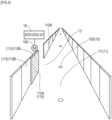
- Dedicated lane 111 is partitioned by fences 110 ( FIG. 3 ) on both sides so that people and general vehicles cannot enter.
- General lane 112 is a lane (vehicle lane) branched from dedicated lane 111 or merging into dedicated lane 111. After branching from dedicated lane 111, bus 5 can travel general lane 112 to arrive at stop 115. Bus 5 departing from stop 115 can travel general lane 112 to merge into dedicated lane 111.
- a major difference between dedicated lane 111 and general lane 112 resides in whether general vehicles other than bus 5 can travel. Because of this difference, the control speed when bus 5 is caused to automatically travel and so forth varies between dedicated lane 111 and general lane 112. While the control speed is on the order of 40 km to 50 km per hour in dedicated lane 111, the control speed is reduced in general lane 112 to be on the order of 0 km to 20 km per hour.
- Fences 110 for partitioning dedicated lane 111 are configured of movable fences 110A of a movable type and fixed fences 110B of a fixed type.
- connection point 13 of dedicated lane 111 to general lane 112 can be set by movement of any movable fence 110A.
- Movable fences 110A are each provided so as to correspond to a specific point that can be set as connection point 13 of general lane 112 with respect to dedicated lane 111, such as a branching point from dedicated lane 111 to general lane 112 or a merging point from general lane 112 to dedicated lane 111.
- Movable fence 110A has a configuration similar to that of a platform door installed in a platform of a train station. Movable fence 110A is provided with drive motor 160 controlled by motor control unit 16. Motor control unit 16 can communicate with control server device 18 via the Internet. Motor control unit 16 causes drive motor 160 to be rotationally driven in response to a control signal from control server device 18.
- Movable fence 110A moves along a lane direction by driving force of drive motor 160 to be displaced to a position overlapping adjacent fixed fence 110B (refer to FIG. 4 ).
- the position where movable fence 110A overlaps fixed fence 110B is an open position where dedicated lane 111 is open to general lane 112.
- a position where movable fence 110A is located between adjacent fixed fences 110B is a closed position where dedicated lane 111 is closed to general lane 112 (refer to FIG. 3 ).
- connection point 13 of dedicated lane 111 with respect to general lane 112 is provided. This allows cross-access between dedicated lane 111 and general lane 112.
- movable fence 110A is at the closed position, accessing from general lane 112 to dedicated lane 111 and branching from dedicated lane 111 to general lane 112 are disabled.
- magnetic markers 10 individually corresponding to respective movable fences 110A are defined in advance.
- the open/closed state of movable fence 110A can be switched depending on whether identification information of magnetic marker 10 (specific marker 10S) positioned so as to correspond to movable fence 110A is stored on a system side as identification information of the connection point. Also, by opening or closing movable fence 110A, setting of connection point 13 of dedicated lane 111 with respect to general lane 112 can be changed.
- General lane 112 for a forward path from dedicated lane 111 toward stop 115 and general lane 112 for a return path from stop 115 toward dedicated lane 111 may be the same or different.
- connection point 13 to dedicated lane 111 may be different.
- the connection point 13 may be a point shared for use in branching and merging, or may be a point only for use in branching or merging.
- Magnetic marker 10 ( FIG. 2 and FIG. 5 ) is a marker with RFID tag 15 (Radio Frequency Identification Tag, wireless tag) integrated with a magnet forming a column having a diameter of 20 mm and a height of 28 mm. Magnetic marker 10 is laid in a state of being accommodated in a hole provided on a road surface 100S ( FIG. 2 ).
- the magnet forming magnetic marker 10 is a ferrite plastic magnet having magnetic powder of iron oxide as a magnetic material dispersed into a polymer material as a base material. This magnet has a maximum energy product (BHmax) of 6.4 kJ/m 3 .
- Magnetic marker 10 acts magnetism with magnetic flux density exceeding 8 ⁇ T (microtesla) at a height of 250 mm as an attachment height of magnetic sensor arrays 21A/B (refer to FIG. 2 ).
- RFID tag 15 which wirelessly outputs tag information is disposed on an end face of the columnar magnet.
- a coating layer made of a resin material may be provided on the surface.
- the coating layer a layer formed of a composite material with fiber impregnated with a resin material may be used.
- sheet-shaped RFID tag 15 may be disposed on the end face of the magnet where the coating layer is formed.
- the coating layer may be provided on the entire or a part of the outer surfaces of the magnet except the end surface where RFID tag 15 is arranged.
- RFID tag 15 ( FIG. 6 ) is an electronic component having IC chip 157 implemented on a surface of tag sheet 150 cut out from, for example, a PET (Polyethylene terephthalate) film.
- IC chip 157 implemented on a surface of tag sheet 150 cut out from, for example, a PET (Polyethylene terephthalate) film.
- a printed pattern of antenna 153 is provided on the surface of tag sheet 150.
- Antenna 153 has both a power-supply-purpose antenna function of causing exciting current to occur by external electromagnetic induction and a communication-purpose antenna function of wirelessly transmitting information such as position data.
- RFID tag 15 operates by wireless external power supply to externally output tag information such as a tag ID as identification information.
- the tag ID to be externally outputted from RFID tag 15 is one example of identification information of magnetic marker 10.
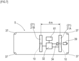
- Bus 5 ( FIG. 2 and FIG. 7 ) is a vehicle capable of automatic driving by remote control.
- Bus 5 includes, as a sensor group for achieving automatic driving, magnetic sensor arrays 21A/B which perform detection of any magnetic marker 10 and so forth, tag reader unit 34 which communicates with RFID tag 15, milli wave radars 37, forward camera 39, and so forth.
- Bus 5 includes, as a configuration for performing traveling control, vehicle onboard ECU (Electronic Control Unit) 61 which controls a steering unit, an engine throttle, a brake actuator, and so forth not depicted.
- ECU Electronic Control Unit
- Milli wave radars 37 are sensors for detecting a three-dimensional target object such as another vehicle, a person, a structure such as a guardrail, a curbstone, or the like. Milli wave radars 37 are arranged at front, rear, left, and right corner portions of the vehicle body so as to be able to monitor the surroundings of bus 5. The detection result of each milli wave radar 37 is inputted to control unit 32.
- Forward camera 39 is a camera which takes an image of forward environments.
- Forward camera 39 is configured to include a processing circuit (omitted in the drawings) which performs image processing. By performing image processing on a taken image, forward camera 39 can detect a road sign, traffic signal, person, bicycle, preceding vehicle, oncoming vehicle, and so forth. The detection result of forward camera 39 is inputted to control unit 32.
- Vehicle onboard ECU 61 can perform control of causing bus 5 to automatically travel based on control information (control values) outputted from control server device 18.
- the control information transmitted from control server device 18 is received by control unit 32, and is transferred to vehicle onboard ECU 61.
- magnetic sensor arrays 21A/B are disposed at two locations four meters apart from each other in a longitudinal direction of bus 5.
- Magnetic sensor arrays 21A/B which are one example of a magnetic detecting part, are bar-shaped units elongated in a vehicle-width direction, and are attached onto the bottom surface of bus 5 in a state of facing road surface 100S.
- Magnetic sensor arrays 21A/B each include fifteen magnetic sensors Cn (n is an integer of 1 to 15) arrayed on a straight line along the vehicle-width direction and detection processing circuit 212 having incorporated therein a CPU not depicted and so forth. In each of magnetic sensor arrays 21A/B, fifteen magnetic sensors Cn are arranged equidistantly with ten-centimeter pitches.
- Magnetic sensors Cn are sensors which detect magnetism by using the known MI effect (Magneto Impedance Effect) in which the impedance of a magneto-sensitive body such as an amorphous wire sensitively changes in response to the external magnetic field.
- MI effect Magnetic Impedance Effect
- magneto-sensitive bodies are arranged along orthogonal biaxial directions, thereby allowing detection of magnetism acting in orthogonal biaxial directions.
- magnetic sensors Cn are incorporated in magnetic sensor arrays 21A/B so as to be able to detect magnetic components in a forwarding direction and the vehicle-width direction.
- Magnetic sensors Cn are highly-sensitive sensors with a measurement range of magnetic flux density of ⁇ 0.6 mT and a magnetic flux resolution of 0.02 ⁇ T in the measurement range.
- magnetic marker 10 can act magnetism with magnetic flux density exceeding 8 ⁇ T at the attachment height of magnetic sensors Cn of 250 mm. With magnetic marker 10 acting magnetism with magnetic flux density exceeding 8 ⁇ T, detection can be made with high reliability by using magnetic sensors Cn with a magnetic flux resolution of 0.02 ⁇ T.
- Detection processing circuit 212 ( FIG. 8 ) of each of magnetic sensor arrays 21A/B is an arithmetic circuit which performs marker detection process for detecting any magnetic marker 10, and so forth.
- This detection processing circuit 212 is configured by using a CPU which performs various arithmetic operations as well as memory elements such as a ROM and RAM, and so forth, which are not depicted.
- Detection processing circuit 212 acquires a sensor signal outputted from each of magnetic sensors Cn at a frequency of 3 kHz to perform marker detection process, and then inputs the detection result of the marker detection process to control unit 32.
- measurement of a lateral shift amount (one example of a relative position in a width direction) with respect to magnetic marker 10 is performed.
- the lateral shift amount with respect to magnetic marker 10 is, for example, a shift amount of the central position (center position) of magnetic sensor array 21 with respect to magnetic marker 10 in the vehicle-width direction.
- the center position of magnetic sensor array 21 is positioned approximately at the center of bus 5 in the vehicle-width direction. Therefore, the shift amount of the center position of magnetic sensor array 21 with respect to magnetic marker 10 can be handled as a lateral shift amount of bus 5 with respect to magnetic marker 10.
- the orientation of bus 5 with respect to the lane direction can be identified. As will be described further below, this identification of the orientation of bus 5 can be performed by control server device 18 which acquires vehicle status information including the lateral shift amounts by the front and rear magnetic sensor arrays 21A/B (two lateral shift amounts).
- Tag reader unit 34 ( FIG. 7 ) is a communication unit which wirelessly communicates with RFID tag 15 retained by magnetic marker 10 ( FIG. 5 ). Tag reader unit 34 wirelessly feeds power required for operation of RFID tag 15 to cause RFID tag 15 to operate, and reads tag ID (tag information) as identification information of RFID tag 15. While magnetic sensor array 21A and tag reader unit 34 are depicted as separately provided in FIG. 7 , a unit with these integrated together may be adopted.
- Control unit 32 ( FIG. 7 ) is a unit which controls magnetic sensor arrays 21A/B, tag reader unit 34, milli wave radar 37, forward camera 39, and so forth and transmits and receives various information and data between control server device 18 (refer to FIG. 1 ).
- Control unit 32 transmits vehicle status information to control server device 18 at a sufficiently fast frequency. To this vehicle status information, a vehicle ID is linked so that bus 5 as a transmission source can be identified on a control server device 18 side. In exchange for transmission of the vehicle status information, control unit 32 acquires control information for automatic traveling from control server device 18. The control information (control values) acquired by control unit 32 is inputted to vehicle onboard ECU 61 and applied to traveling control of bus 5, thereby achieving remote control of bus 5 by control server device 18.
- the vehicle status information includes information acquired from the outside of the vehicle and information indicating a traveling state of bus 5.
- the information acquired from the outside of the vehicle includes the tag ID (tag information) acquired from RFID tag 15 retained in magnetic marker 10, the lateral shift amount with respect to magnetic marker 10, the detection result by milli wave radar 37, the detection result by forward camera 39, and so forth.
- the information indicating the traveling state of bus 5 includes a vehicle speed, steering angle, yaw rate, and so forth.
- the lateral shift amount with respect to magnetic marker 10 and the tag ID are included in the above-described vehicle status information only when any magnetic marker 10 is detected.
- Control server device 18 ( FIG. 9 ) is a computer device configured mainly of electronic substrate 180 having implemented thereon electronic components such as CPU (Central Processing Unit) 181, ROM (Read Only Memory) 182, and RAM (Random Access Memory) 183.
- CPU Central Processing Unit
- ROM Read Only Memory
- RAM Random Access Memory
- I/O Input/Output
- marker database (marker DB) 185M storing marker information regarding each magnetic marker
- map database (map DB) 185T storing map data representing a three-dimensional structure of traveling lane 11
- connection point database (connection point DB) 185C storing identification information of magnetic marker 10 positioned so as to correspond to connection point 13 between dedicated lane 111 and general lane 112 as connection point identification information
- the position of each movable fence 110A is managed. For example, in the storage area of storage device 185, flag data is stored for each movable fence 110A, representing whether it is at an open position or a closed position. By referring to the flag data, control server device 18 can grasp the state of corresponding movable fence 110A.
- the tag ID (tag information), which is identification information of RFID tag 15 provided is linked (associated).
- the marker information includes information representing the laying position, information representing an attribute of that laying position, regulation information such as a speed limit, and so forth.
- the marker information of magnetic marker 10 positioned so as to correspond to movable fence 110A includes identification information for identifying movable fence 110A.
- the map data stored in map DB 185T is configured of vector data representing the structure of traveling lane 11, surrounding environments, and so forth.
- this map data the laying position of magnetic marker 10 and so forth are mapped on traveling lane 11. For example, when bus 5 detects any magnetic marker 10, a lane shape ahead of bus 5 can be acquired by referring to this map data.
- Connection point DB 185C forms one example of a storage part which stores the tag ID, which is identification information of magnetic marker 10 positioned so as to correspond to connection point 13 set by a setting part described further below, as identification information of the connection point.
- the tag ID is linked to the marker information stored in marker DB 185M.
- the marker information of magnetic marker 10 corresponding to movable fence 110A further includes identification information for identifying movable fence 110A. Therefore, based on the tag ID stored in connection point DB 185C as connection point identification information, movable fence 110A forming connection point 13, that is, movable fence 110A as a target controlled to be at an open position, can be identified.
- connection point 13 To the tag ID stored in connection point DB 185C as connection point identification information, attribute information of connection point 13 is linked. There are two types of attribution information, branching and merging.
- the attribution information of branching represents that connection point 13 is for a branch from dedicated lane 111 to general lane 112.
- the attribute information of merging represents that connection point 13 is for a merge from general lane 112 to dedicated lane 111.
- control server device 18 achieves functions as the following respective configurations.
- the marker detection process is a process to be performed by magnetic sensor arrays 21A/B (refer to FIG. 8 ). Magnetic sensor arrays 21A/B performs the marker detection process by using magnetic sensors Cn at a frequency of 3 kHz.
- magnetic sensors Cn are configured to measure magnetic components in the forwarding direction and the vehicle-width direction of bus 5. For example, when these magnetic sensors Cn move in the forward direction and pass over directly above any magnetic marker 10, the sign of a magnetic measurement value in the forwarding direction is reversed before and after magnetic marker 10 as in FIG. 10 , and the value changes so as to cross zero at a position directly above magnetic marker 10. Therefore, during traveling of bus 5, when zero-cross Zc occurs where the sign of magnetism in the forwarding direction detected by any magnetic sensor Cn is reversed, it can be determined that magnetic sensor arrays 21A/B are positioned directly above magnetic marker 10. Detection processing circuit 212 determines that magnetic marker 10 is detected when magnetic sensor arrays 21A/B are positioned directly above magnetic marker 10 and zero-cross Zc of the magnetic measurement value in the forwarding direction occurs.
- magnetic sensors with specifications same as those of magnetic sensors Cn
- the sign of the magnetic measurement value in the vehicle-width direction is reversed on both sides of magnetic marker 11, and the value changes so as to cross zero at a position directly above magnetic marker 10.
- the sign of magnetism in the vehicle-width direction to be detected by magnetic sensor Cn differs depending on which side the magnetic sensor is present with respect to magnetic marker 10 ( FIG. 11 ).
- FIG. 11 exemplarily depicting magnetic measurement values in the vehicle-width direction of each magnetic sensor Cn belonging to magnetic sensor arrays 21A/B, an intermediate position between adjacent two magnetic sensors Cn across zero-cross Zc where the sign of magnetism in the vehicle-width direction is reversed or a position directly below magnetic sensor Cn where magnetism in the vehicle-width direction to be detected is zero and with the signs of magnetic sensors Cn on both outer sides being reversed is a position of magnetic marker 10 in the vehicle-width direction.
- Detection processing circuit 212 measures a positional deviation (deviation with respect to magnetic marker 10) in the vehicle-width direction of the center position (for example, the position of magnetic sensor C8) in magnetic sensor arrays 21A/B as the above-described lateral shift amount.
- the position of zero-cross Zc is a position corresponding to C9.5, which is approximately a midpoint between C9 and C10.
- the lateral shift amount with respect to magnetic marker 10 is (9.5-8) ⁇ 10 centimeters with reference to C8 positioned at the center of magnetic sensor arrays 21A/B in the vehicle-width direction.
- FIG. 12 is a flow diagram depicting a flow of operation from a time when the bus follows a branch from dedicated lane 111 (refer to FIG. 1 ) to general lane 112 until it stops at stop 115.
- FIG. 13 is a flow diagram depicting a flow of operation from a time when the bus departs from stop 115 until it merges into dedicated lane 111.
- magnetic marker 10 positioned so as to corresponding to connection point 13 for merging or branching is referred to as specific marker 10S.
- bus 5 transmits the above-described vehicle status information to control server device 18 at a sufficiently fast frequency.
- the vehicle status information when any magnetic marker 10 is detected includes the lateral shift amounts with respect to two front and rear magnetic markers 10 detected by magnetic sensor arrays 21A/B, the tag ID of RFID tag 15 provided to front magnetic marker 10 detected by magnetic sensor array 21A, and so forth.
- control server device 18 On receiving the vehicle status information including the lateral shift amounts and the tag ID, control server device 18 calculates control values for bus 5 to follow magnetic marker 10, and transmits the control values to bus 5 as control information.
- Control unit 32 of bus 5 inputs the received control information to vehicle onboard ECU 61 to cause bus 5 to automatically travel by remote control.
- control information including an interrupt instruction such as emergency brake is transmitted, thereby allowing bus 5 to stop.
- control server device 18 refers to the storage area of connection point DB 185C. From the storage area of connection point DB 185C, control server device 18 reads the tag ID (connection point identification information) to which the attribute information for branching is linked. Then, control server device 18 refers to marker DB 185M by using the tag ID read from connection point DB 185C, and identifies specific marker 10S, which is magnetic marker 10 positioned so as to correspond to connection point 13. With this, control server device 18 identifies the position of connection point 13 for branching ahead. Also, control server device 18 refers to map DB 185T, and identifies tenth magnetic marker 10 positioned before specific marker 10S.
- Control server device 18 causes bus 5 to continue to automatically travel along dedicated lane 111 (S102: NO ⁇ S101) until tenth magnetic marker 10 before specific marker 10S is detected (S102). Then, when tenth magnetic marker 10 before specific marker 10S is detected (S102: YES), control server device 18 switches the traveling state of bus 5 to slow traveling (S103).
- control server device 18 causes slow traveling of bus 5 to continue until specific marker 10S is detected (S104: NO ⁇ S103).
- control server device 18 applies branching control to bus 5 (S105).
- Control server device 18 then remotely controls bus 5 so that it travels general lane 112 in accordance with the end of branching control (S106).
- Control server device 18 causes bus 5 to travel along general lane 112 until it arrives at stop 115 (S107: NO ⁇ S106).
- control server device 18 causes bus 5 to stop at stop 115 so as to allow users to get off or get on (S108).
- control server device 18 causes bus 5 to branch from dedicated lane 111 and enter general lane 112 provided with stop 115. As with the case of dedicated lane 111, control server device 18 remotely controls bus 5 so that it travels general lane 112 by following magnetic markers 10. However, in dedicated lane 111 and general lane 112, remote control mode by control server device 18 is different. For example, one difference in control between dedicated lane 111 and general lane 112 resides in control speed. As described above, compared with the control speed on dedicated lane 111, the control speed on general lane 112 is set slow. This is because there is a possibility of encountering a person, another vehicle, and so forth on general lane 112 and the bus is required to immediately stop when the possibility of contact occurs.
- control server device 18 After users get on and off (S201 in FIG. 13 : YES), control server device 18 causes bus 5 to start.
- control server device 18 refers to the storage area of connection point DB 185C.
- control server device 18 reads the tag ID (connection point identification information) to which attribute information for merging is linked from the storage area of connection point DB 185C, and identifies specific marker 10S according to the tag ID.
- This specific marker 10S is magnetic marker 10 positioned so as to correspond to connection point 13 merging from general lane 112 to dedicated lane 111.
- control server device 18 identifies magnetic marker 10 adjacent to specific marker 10S, that is, last magnetic marker 10 before merging.
- Control server device 18 remotely controls bus 5 to cause it to travel general lane 112 (S202). Thereafter when last magnetic marker 10 before merging is detected (S203: YES), control server device 18 applies merging control to bus 5 (S204). Then, when specific marker 10S positioned so as to correspond to connection point 13 merging from general lane 112 into dedicated lane 111 is detected (S205: YES), control server device 18 remotely controls bus 5 so that it can travel dedicated lane 111 (S206).
- bus 5 on general lane 112 or dedicated lane 111 may be caused to reduce speed or wait at a position before connection point 13 for merging. In this case, the possibility of interference between bus merging into dedicated lane 111 and bus 5 traveling dedicated lane 111 can be avoided in advance.
- connection point 13 between dedicated lane 111 and general lane 112 can be changed whenever necessary by remote control by control server device 18.
- control server device 18 When movable fence 110A is displaced to the open position, connection point 13 between dedicated lane 111 and general lane 112 is set.
- connection point 13 between dedicated lane 111 and general lane 112 is canceled.
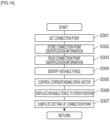
- connection point identification information for identifying that connection point 13 is stored in connection point DB 185C (S302).
- the connection point identification information of the present embodiment is a tag ID, which is identification information of magnetic marker 10 positioned so as to correspond to connection point 13.
- Control server device 18 refers to the storage area of connection point DB 185C whenever necessary to read the tag ID stored as connection point identification information (S303). Then, control server device 18 identifies connection point 13 based on the read tag ID (connection point identification information), and also identifies corresponding movable fence 110A (S304).
- control server device 18 controls corresponding drive motor 160 (S305) to displace movable fence 110A to the open position (S306).
- connection point 13 is set by the process as described above (S307).
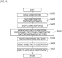
- connection point identification information which can identify that connection point 13 is erased from connection point DB 185C (S402).
- the connection point identification information is the tag ID, which is identification information of magnetic marker 10 positioned so as to correspond to connection point 13.
- Control server device 18 refers to the storage area of connection point DB 185C whenever necessary (S403) to identify, among movable fences 110A controlled at the open position, a fence the tag ID of which as connection point identification information is not stored (S404). Then, control server device 18 controls drive motor 160 corresponding to movable fence 110A identified at step S404 (S405) to displace that movable fence 110A from the open position to the closed position (S406). In operation system 1, connection point 13 is cancelled by the process as described above (S407).
- connection point 13 can be set. Furthermore, by erasing the tag ID as connection point identification information, movable fence 110A corresponding to magnetic marker 10 according to that tag ID can be displaced from the open position to the closed position. Then, in operation system 1, with movable fence 110A displaced to the closed position, connection point 13 can be cancelled.
- connection point 13 between dedicated lane 111 and general lane 112 can be set or cancelled.
- the tag ID of magnetic marker 10 positioned correspondingly may be stored and registered in connection point DB 185C as connection point identification information.
- bus 5 can be selectively caused to head only toward stop 115 where the user desiring to get on or off waits.
- connection point 13 can be set to dedicated lane 111 as appropriate.
- a position where vehicle should temporarily stop and positions at the start and the end of a deceleration section may be able to be set as appropriate.
- these points can also be set/cancelled by storing/erasing identification information of the corresponding magnetic marker.
- general lane 112 leading to stop 115 is exemplarily described as another lane.
- this another lane may be sub-lane 111S for dedicated lane 111.
- Stop 115 may be set in sub-lane 111S.
- a destination in general lane 112 may be a place other than stop 115.
- general lane 112 may simply be used as a detour. By providing general lane 112 as a detour, for example, it is possible to flexibly address, for example, a route change due to road construction work or the like, and so forth.
- the separating zone may be eliminated as in FIG. 17 and dedicated lane 111 and sub-lane 111S may be provided in one lane.
- the lane width of the point provided with stop 115 is widened.
- dedicated lane 111 forming a main route of the bus passing through the stop without stopping and another lane 111T forming a subroute of the bus to stop at the stop are provided in parallel.
- bus 5 automatically travels also general lane 112.
- bus 5 may travel by manual operation (manually travel) by the driver.
- switching may be made between automatic traveling and manual traveling.
- the configuration is exemplarily described in which bus 5 automatically travels by remote control by control server device 18.
- control unit 32 of bus 5 may calculate control values for automatic driving. In this case, bus 5 can autonomously travel.
- the configuration is exemplarily described in which sheet-like RFID tag 15 is attached to the upper surface of magnetic marker 10.
- the configuration in which magnetic marker 10 and RFID tag 15 are integrated is not a requisite. It is only required that magnetic marker 10 and RFID tag 15 be arrange at the same position, and RFID tag 15 may be arranged above or below magnetic marker 10 in a vertical direction.
- Magnetic marker 10 of the present embodiment is a marker integrated with RFID tag 15.
- a magnetic marker not provided with RFID tag 15 may be included.
- magnetic marker 10 integrated with RFID tag 15 is adopted as a magnetic marker positioned so as to correspond to movable fence 110A, a magnetic marker not provided with RFID tag 15 may be adopted as another magnetic marker.
- setting/cancelling connection point 13 is controlled depending on whether identification information (tag ID in the present embodiment) of magnetic marker 10 corresponding to connection point 13 is stored in connection point DB 185C as connection point identification information.
- identification information of all magnetic markers 10 corresponding to positions as candidates for connection point 13 may be stored in connection point DB 185C, each as being provided with a flag.
- the flag is a flag indicating whether the position is set as connection point 13.
- the identification information of magnetic marker 10 with the flag ON is connection point identification information.
- the identification information of magnetic marker 10 with the flag OFF is not connection point identification information.
- switching the flag to OFF corresponds to erasing the connection point identification information.
- switching the flag to ON corresponds to newly storing the connection point identification information.
- connection point 13 magnetic marker 10 positioned so as to correspond to connection point 13 is exemplarily described.
- "Positioned so as to correspond to connection point 13" means that a position relation between connection point 13 and magnetic marker 10 is substantially constant and, if the position of corresponding magnetic marker 10 can be identified, the position of connection point 13 can be identified.
- Magnetic marker 10 corresponding to connection point 13 may be one that can identify corresponding connection point 13 when any magnetic marker 10 is identified. In the forwarding direction of bus 5, connection point 13 may be positioned downstream of corresponding magnetic marker 10, or vice versa.
- map DB 185T magnetic marker 10 positioned on an upstream side with respect to corresponding magnetic marker 10 can be grasped. In accordance with detection of magnetic marker 10 positioned on the upstream side, an approach of bus 5 to connection point 13 may be recognized.
Landscapes
- Engineering & Computer Science (AREA)
- Physics & Mathematics (AREA)
- General Physics & Mathematics (AREA)
- Automation & Control Theory (AREA)
- Radar, Positioning & Navigation (AREA)
- Remote Sensing (AREA)
- Mechanical Engineering (AREA)
- Transportation (AREA)
- Human Computer Interaction (AREA)
- Aviation & Aerospace Engineering (AREA)
- Electromagnetism (AREA)
- Architecture (AREA)
- Civil Engineering (AREA)
- Structural Engineering (AREA)
- Traffic Control Systems (AREA)
- Platform Screen Doors And Railroad Systems (AREA)
- Control Of Position, Course, Altitude, Or Attitude Of Moving Bodies (AREA)
Applications Claiming Priority (2)
| Application Number | Priority Date | Filing Date | Title |
|---|---|---|---|
| JP2020135444A JP7437601B2 (ja) | 2020-08-08 | 2020-08-08 | 運行システム及び運行システムの制御方法 |
| PCT/JP2021/029093 WO2022034849A1 (fr) | 2020-08-08 | 2021-08-05 | Système d'actionnement et procédé de commande pour système d'actionnement |
Publications (3)
| Publication Number | Publication Date |
|---|---|
| EP4194305A1 true EP4194305A1 (fr) | 2023-06-14 |
| EP4194305A4 EP4194305A4 (fr) | 2024-06-19 |
| EP4194305B1 EP4194305B1 (fr) | 2025-06-25 |
Family
ID=80247852
Family Applications (1)
| Application Number | Title | Priority Date | Filing Date |
|---|---|---|---|
| EP21855928.4A Active EP4194305B1 (fr) | 2020-08-08 | 2021-08-05 | Système d'actionnement et procédé de commande pour système d'actionnement |
Country Status (5)
| Country | Link |
|---|---|
| US (1) | US12246746B2 (fr) |
| EP (1) | EP4194305B1 (fr) |
| JP (1) | JP7437601B2 (fr) |
| CN (1) | CN116034070B (fr) |
| WO (1) | WO2022034849A1 (fr) |
Families Citing this family (3)
| Publication number | Priority date | Publication date | Assignee | Title |
|---|---|---|---|---|
| US11604476B1 (en) * | 2018-10-05 | 2023-03-14 | Glydways Inc. | Road-based vehicle guidance system |
| JP7653809B2 (ja) * | 2021-03-12 | 2025-03-31 | 三菱電機株式会社 | 車両運用支援装置、端末装置、車両運用支援システム、車両設置端末、車両制御装置、車両、車両運用支援方法および車両運用支援プログラム |
| WO2023058344A1 (fr) * | 2021-10-04 | 2023-04-13 | 日立Astemo株式会社 | Dispositif de commande de véhicule |
Family Cites Families (25)
| Publication number | Priority date | Publication date | Assignee | Title |
|---|---|---|---|---|
| US4361202A (en) * | 1979-06-15 | 1982-11-30 | Michael Minovitch | Automated road transportation system |
| JPS6384608U (fr) * | 1986-11-19 | 1988-06-03 | ||
| JP2784253B2 (ja) * | 1990-09-04 | 1998-08-06 | 株式会社ダイフク | 移動車の走行制御装置 |
| JP3407950B2 (ja) * | 1993-10-14 | 2003-05-19 | 東日本旅客鉄道株式会社 | ホームドア装置の可動柵給電装置 |
| JP3024963B1 (ja) * | 1998-11-17 | 2000-03-27 | 川崎重工業株式会社 | プラットホーム保護柵装置 |
| JP2000259987A (ja) * | 1999-03-11 | 2000-09-22 | Toyota Motor Corp | 車両運行支援装置およびその装置を有する交通システム |
| JP2000264196A (ja) * | 1999-03-12 | 2000-09-26 | Toyota Motor Corp | ガイドウエイ交通システムに用いられる自動運転車両 |
| JP2001233200A (ja) * | 2000-02-25 | 2001-08-28 | Mitsubishi Electric Corp | プラットホームドア装置 |
| JP2010097253A (ja) | 2008-10-14 | 2010-04-30 | Ihi Corp | バス運行システム |
| CN102787538A (zh) * | 2012-08-17 | 2012-11-21 | 上海市城市建设设计研究总院 | 可变公交专用道系统 |
| CN103850204A (zh) * | 2012-12-06 | 2014-06-11 | 都快通(北京)交通疏导设备有限公司 | 一种活动隔离栏和应用该装置的交通疏导系统 |
| US20150294566A1 (en) * | 2014-04-15 | 2015-10-15 | Tomorrow's Transportation Today | Trip planning and management methods for an intelligent transit system with electronic guided buses |
| US10025990B2 (en) * | 2014-05-21 | 2018-07-17 | Universal City Studios Llc | System and method for tracking vehicles in parking structures and intersections |
| US10878249B2 (en) * | 2015-10-07 | 2020-12-29 | Accenture Global Solutions Limited | Border inspection with aerial cameras |
| JP6544486B2 (ja) * | 2016-04-28 | 2019-07-17 | 愛知製鋼株式会社 | 磁気マーカ及び運転支援システム |
| JP7012421B2 (ja) | 2016-06-17 | 2022-01-28 | 愛知製鋼株式会社 | 磁気マーカ及びマーカシステム |
| DE102016010414A1 (de) * | 2016-08-30 | 2018-03-01 | Engin Kasli | Vorrichtung zur Spurführung autonom fahrender Kraftfahrzeuge |
| CN206292974U (zh) * | 2016-12-26 | 2017-06-30 | 上海工程技术大学 | 一种潮汐可变车道控制装置 |
| CN107178051B (zh) * | 2017-06-22 | 2022-08-26 | 南京蓝泰交通设施有限责任公司 | 一种适合潮汐车道的智能可移动隔离护栏系统及其控制方法 |
| JP6828643B2 (ja) * | 2017-09-12 | 2021-02-10 | 愛知製鋼株式会社 | 位置捕捉システム及び位置捕捉方法 |
| JP6641583B2 (ja) * | 2018-01-31 | 2020-02-05 | 本田技研工業株式会社 | 車両制御装置、車両制御方法、およびプログラム |
| JP7098366B2 (ja) * | 2018-03-15 | 2022-07-11 | 本田技研工業株式会社 | 車両制御装置、車両制御方法、およびプログラム |
| US12539889B2 (en) * | 2019-08-27 | 2026-02-03 | Universal City Studios Llc | Gate systems and methods for rotating loading platform |
| CN111137294B (zh) * | 2019-12-30 | 2022-04-05 | 潍柴动力股份有限公司 | 智能汽车及其控制方法 |
| CN111243284B (zh) * | 2019-12-31 | 2021-08-06 | 宁波宁工交通工程设计咨询有限公司 | 智能隔离护栏的控制方法、存储介质、终端及隔离护栏 |
-
2020
- 2020-08-08 JP JP2020135444A patent/JP7437601B2/ja active Active
-
2021
- 2021-08-05 WO PCT/JP2021/029093 patent/WO2022034849A1/fr not_active Ceased
- 2021-08-05 EP EP21855928.4A patent/EP4194305B1/fr active Active
- 2021-08-05 CN CN202180056939.8A patent/CN116034070B/zh active Active
- 2021-08-05 US US18/020,268 patent/US12246746B2/en active Active
Also Published As
| Publication number | Publication date |
|---|---|
| CN116034070B (zh) | 2025-11-21 |
| US12246746B2 (en) | 2025-03-11 |
| EP4194305B1 (fr) | 2025-06-25 |
| JP2022031596A (ja) | 2022-02-21 |
| CN116034070A (zh) | 2023-04-28 |
| JP7437601B2 (ja) | 2024-02-26 |
| US20230271630A1 (en) | 2023-08-31 |
| WO2022034849A1 (fr) | 2022-02-17 |
| EP4194305A4 (fr) | 2024-06-19 |
Similar Documents
| Publication | Publication Date | Title |
|---|---|---|
| JP7464870B2 (ja) | 自動駐車システム | |
| EP4194305B1 (fr) | Système d'actionnement et procédé de commande pour système d'actionnement | |
| EP3828659B1 (fr) | Système pour véhicule | |
| EP3605487A1 (fr) | Système de marqueur | |
| US11127287B2 (en) | System, method, and computer-readable storage medium for determining road type | |
| US20220306099A1 (en) | Method and track guidance system for controlling an autonomous motor vehicle in an urban area | |
| CN113993762B (zh) | 车辆用的控制方法 | |
| WO2019156194A1 (fr) | Système de véhicule | |
| EP3690848B1 (fr) | Système de véhicule et procédé de communication d'étiquette | |
| Yoshioka et al. | Bus corridor operational improvement with intelligent transportation system based on autonomous guidance and precision docking | |
| CN111095376A (zh) | 车辆用系统以及标签通信方法 | |
| US20240400046A1 (en) | Control method and control system | |
| US12322285B2 (en) | Information acquisition method and vehicular system | |
| US12602055B2 (en) | Vehicular system | |
| US20020169528A1 (en) | Electronically tracked road-map system | |
| WO2020175439A1 (fr) | Procédé d'estimation d'emplacement, et système d'estimation d'emplacement | |
| BR102014021691B1 (pt) | Sistema de transporte autônomo rodoviário por ferrovias virtuais | |
| SK50782016U1 (sk) | Identifikátor pre i-vozovku, i-vozovka, i-vozidlo automatického transportného systému a spôsob navigácie i-vozidla po i-vozovke |
Legal Events
| Date | Code | Title | Description |
|---|---|---|---|
| STAA | Information on the status of an ep patent application or granted ep patent |
Free format text: STATUS: THE INTERNATIONAL PUBLICATION HAS BEEN MADE |
|
| PUAI | Public reference made under article 153(3) epc to a published international application that has entered the european phase |
Free format text: ORIGINAL CODE: 0009012 |
|
| STAA | Information on the status of an ep patent application or granted ep patent |
Free format text: STATUS: REQUEST FOR EXAMINATION WAS MADE |
|
| 17P | Request for examination filed |
Effective date: 20230126 |
|
| AK | Designated contracting states |
Kind code of ref document: A1 Designated state(s): AL AT BE BG CH CY CZ DE DK EE ES FI FR GB GR HR HU IE IS IT LI LT LU LV MC MK MT NL NO PL PT RO RS SE SI SK SM TR |
|
| DAV | Request for validation of the european patent (deleted) | ||
| DAX | Request for extension of the european patent (deleted) | ||
| REG | Reference to a national code |
Ref country code: DE Ref legal event code: R079 Free format text: PREVIOUS MAIN CLASS: B61B0013000000 Ipc: G05D0001000000 Ref country code: DE Ref legal event code: R079 Ref document number: 602021033048 Country of ref document: DE Free format text: PREVIOUS MAIN CLASS: B61B0013000000 Ipc: G05D0001000000 |
|
| A4 | Supplementary search report drawn up and despatched |
Effective date: 20240517 |
|
| RIC1 | Information provided on ipc code assigned before grant |
Ipc: G08G 1/00 20060101ALI20240513BHEP Ipc: B61B 13/00 20060101ALI20240513BHEP Ipc: G05D 1/00 20060101AFI20240513BHEP |
|
| RIC1 | Information provided on ipc code assigned before grant |
Ipc: G08G 1/127 20060101ALI20241223BHEP Ipc: G08G 1/0968 20060101ALI20241223BHEP Ipc: G08G 1/095 20060101ALI20241223BHEP Ipc: E01F 9/30 20160101ALI20241223BHEP Ipc: G05D 1/00 20060101AFI20241223BHEP |
|
| GRAP | Despatch of communication of intention to grant a patent |
Free format text: ORIGINAL CODE: EPIDOSNIGR1 |
|
| STAA | Information on the status of an ep patent application or granted ep patent |
Free format text: STATUS: GRANT OF PATENT IS INTENDED |
|
| INTG | Intention to grant announced |
Effective date: 20250207 |
|
| P01 | Opt-out of the competence of the unified patent court (upc) registered |
Free format text: CASE NUMBER: APP_14167/2025 Effective date: 20250321 |
|
| GRAS | Grant fee paid |
Free format text: ORIGINAL CODE: EPIDOSNIGR3 |
|
| GRAA | (expected) grant |
Free format text: ORIGINAL CODE: 0009210 |
|
| STAA | Information on the status of an ep patent application or granted ep patent |
Free format text: STATUS: THE PATENT HAS BEEN GRANTED |
|
| AK | Designated contracting states |
Kind code of ref document: B1 Designated state(s): AL AT BE BG CH CY CZ DE DK EE ES FI FR GB GR HR HU IE IS IT LI LT LU LV MC MK MT NL NO PL PT RO RS SE SI SK SM TR |
|
| REG | Reference to a national code |
Ref country code: GB Ref legal event code: FG4D |
|
| REG | Reference to a national code |
Ref country code: CH Ref legal event code: EP |
|
| REG | Reference to a national code |
Ref country code: CH Ref legal event code: EP |
|
| REG | Reference to a national code |
Ref country code: IE Ref legal event code: FG4D |
|
| REG | Reference to a national code |
Ref country code: DE Ref legal event code: R096 Ref document number: 602021033048 Country of ref document: DE |
|
| PG25 | Lapsed in a contracting state [announced via postgrant information from national office to epo] |
Ref country code: FI Free format text: LAPSE BECAUSE OF FAILURE TO SUBMIT A TRANSLATION OF THE DESCRIPTION OR TO PAY THE FEE WITHIN THE PRESCRIBED TIME-LIMIT Effective date: 20250625 |
|
| PGFP | Annual fee paid to national office [announced via postgrant information from national office to epo] |
Ref country code: DE Payment date: 20250820 Year of fee payment: 5 |
|
| REG | Reference to a national code |
Ref country code: LT Ref legal event code: MG9D |
|
| PG25 | Lapsed in a contracting state [announced via postgrant information from national office to epo] |
Ref country code: NO Free format text: LAPSE BECAUSE OF FAILURE TO SUBMIT A TRANSLATION OF THE DESCRIPTION OR TO PAY THE FEE WITHIN THE PRESCRIBED TIME-LIMIT Effective date: 20250925 Ref country code: GR Free format text: LAPSE BECAUSE OF FAILURE TO SUBMIT A TRANSLATION OF THE DESCRIPTION OR TO PAY THE FEE WITHIN THE PRESCRIBED TIME-LIMIT Effective date: 20250926 |
|
| PG25 | Lapsed in a contracting state [announced via postgrant information from national office to epo] |
Ref country code: BG Free format text: LAPSE BECAUSE OF FAILURE TO SUBMIT A TRANSLATION OF THE DESCRIPTION OR TO PAY THE FEE WITHIN THE PRESCRIBED TIME-LIMIT Effective date: 20250625 |
|
| PGFP | Annual fee paid to national office [announced via postgrant information from national office to epo] |
Ref country code: GB Payment date: 20250820 Year of fee payment: 5 |
|
| PG25 | Lapsed in a contracting state [announced via postgrant information from national office to epo] |
Ref country code: HR Free format text: LAPSE BECAUSE OF FAILURE TO SUBMIT A TRANSLATION OF THE DESCRIPTION OR TO PAY THE FEE WITHIN THE PRESCRIBED TIME-LIMIT Effective date: 20250625 |
|
| PGFP | Annual fee paid to national office [announced via postgrant information from national office to epo] |
Ref country code: AT Payment date: 20251020 Year of fee payment: 5 Ref country code: FR Payment date: 20250828 Year of fee payment: 5 |
|
| PG25 | Lapsed in a contracting state [announced via postgrant information from national office to epo] |
Ref country code: RS Free format text: LAPSE BECAUSE OF FAILURE TO SUBMIT A TRANSLATION OF THE DESCRIPTION OR TO PAY THE FEE WITHIN THE PRESCRIBED TIME-LIMIT Effective date: 20250925 |
|
| PG25 | Lapsed in a contracting state [announced via postgrant information from national office to epo] |
Ref country code: LV Free format text: LAPSE BECAUSE OF FAILURE TO SUBMIT A TRANSLATION OF THE DESCRIPTION OR TO PAY THE FEE WITHIN THE PRESCRIBED TIME-LIMIT Effective date: 20250625 |
|
| REG | Reference to a national code |
Ref country code: NL Ref legal event code: MP Effective date: 20250625 |
|
| PG25 | Lapsed in a contracting state [announced via postgrant information from national office to epo] |
Ref country code: NL Free format text: LAPSE BECAUSE OF FAILURE TO SUBMIT A TRANSLATION OF THE DESCRIPTION OR TO PAY THE FEE WITHIN THE PRESCRIBED TIME-LIMIT Effective date: 20250625 |
|
| PG25 | Lapsed in a contracting state [announced via postgrant information from national office to epo] |
Ref country code: PT Free format text: LAPSE BECAUSE OF FAILURE TO SUBMIT A TRANSLATION OF THE DESCRIPTION OR TO PAY THE FEE WITHIN THE PRESCRIBED TIME-LIMIT Effective date: 20251027 |
|
| REG | Reference to a national code |
Ref country code: AT Ref legal event code: MK05 Ref document number: 1807105 Country of ref document: AT Kind code of ref document: T Effective date: 20250625 |
|
| PG25 | Lapsed in a contracting state [announced via postgrant information from national office to epo] |
Ref country code: IS Free format text: LAPSE BECAUSE OF FAILURE TO SUBMIT A TRANSLATION OF THE DESCRIPTION OR TO PAY THE FEE WITHIN THE PRESCRIBED TIME-LIMIT Effective date: 20251025 |
|
| PG25 | Lapsed in a contracting state [announced via postgrant information from national office to epo] |
Ref country code: AT Free format text: LAPSE BECAUSE OF FAILURE TO SUBMIT A TRANSLATION OF THE DESCRIPTION OR TO PAY THE FEE WITHIN THE PRESCRIBED TIME-LIMIT Effective date: 20250625 Ref country code: SM Free format text: LAPSE BECAUSE OF FAILURE TO SUBMIT A TRANSLATION OF THE DESCRIPTION OR TO PAY THE FEE WITHIN THE PRESCRIBED TIME-LIMIT Effective date: 20250625 |
|
| PG25 | Lapsed in a contracting state [announced via postgrant information from national office to epo] |
Ref country code: CZ Free format text: LAPSE BECAUSE OF FAILURE TO SUBMIT A TRANSLATION OF THE DESCRIPTION OR TO PAY THE FEE WITHIN THE PRESCRIBED TIME-LIMIT Effective date: 20250625 |
|
| PG25 | Lapsed in a contracting state [announced via postgrant information from national office to epo] |
Ref country code: PL Free format text: LAPSE BECAUSE OF FAILURE TO SUBMIT A TRANSLATION OF THE DESCRIPTION OR TO PAY THE FEE WITHIN THE PRESCRIBED TIME-LIMIT Effective date: 20250625 |
|
| PG25 | Lapsed in a contracting state [announced via postgrant information from national office to epo] |
Ref country code: EE Free format text: LAPSE BECAUSE OF FAILURE TO SUBMIT A TRANSLATION OF THE DESCRIPTION OR TO PAY THE FEE WITHIN THE PRESCRIBED TIME-LIMIT Effective date: 20250625 |
|
| PG25 | Lapsed in a contracting state [announced via postgrant information from national office to epo] |
Ref country code: SK Free format text: LAPSE BECAUSE OF FAILURE TO SUBMIT A TRANSLATION OF THE DESCRIPTION OR TO PAY THE FEE WITHIN THE PRESCRIBED TIME-LIMIT Effective date: 20250625 |
|
| PG25 | Lapsed in a contracting state [announced via postgrant information from national office to epo] |
Ref country code: ES Free format text: LAPSE BECAUSE OF FAILURE TO SUBMIT A TRANSLATION OF THE DESCRIPTION OR TO PAY THE FEE WITHIN THE PRESCRIBED TIME-LIMIT Effective date: 20250625 |
|
| PG25 | Lapsed in a contracting state [announced via postgrant information from national office to epo] |
Ref country code: RO Free format text: LAPSE BECAUSE OF FAILURE TO SUBMIT A TRANSLATION OF THE DESCRIPTION OR TO PAY THE FEE WITHIN THE PRESCRIBED TIME-LIMIT Effective date: 20250625 |
|
| REG | Reference to a national code |
Ref country code: CH Ref legal event code: H13 Free format text: ST27 STATUS EVENT CODE: U-0-0-H10-H13 (AS PROVIDED BY THE NATIONAL OFFICE) Effective date: 20260324 |
|
| PG25 | Lapsed in a contracting state [announced via postgrant information from national office to epo] |
Ref country code: MC Free format text: LAPSE BECAUSE OF FAILURE TO SUBMIT A TRANSLATION OF THE DESCRIPTION OR TO PAY THE FEE WITHIN THE PRESCRIBED TIME-LIMIT Effective date: 20250625 |
|
| PG25 | Lapsed in a contracting state [announced via postgrant information from national office to epo] |
Ref country code: DK Free format text: LAPSE BECAUSE OF FAILURE TO SUBMIT A TRANSLATION OF THE DESCRIPTION OR TO PAY THE FEE WITHIN THE PRESCRIBED TIME-LIMIT Effective date: 20250625 |
|
| PG25 | Lapsed in a contracting state [announced via postgrant information from national office to epo] |
Ref country code: LU Free format text: LAPSE BECAUSE OF NON-PAYMENT OF DUE FEES Effective date: 20250805 Ref country code: IT Free format text: LAPSE BECAUSE OF FAILURE TO SUBMIT A TRANSLATION OF THE DESCRIPTION OR TO PAY THE FEE WITHIN THE PRESCRIBED TIME-LIMIT Effective date: 20250625 |