EP4194309B1 - Coupleur de véhicule ferroviaire et véhicule ferroviaire doté d'un coupleur - Google Patents
Coupleur de véhicule ferroviaire et véhicule ferroviaire doté d'un coupleur Download PDFInfo
- Publication number
- EP4194309B1 EP4194309B1 EP21213243.5A EP21213243A EP4194309B1 EP 4194309 B1 EP4194309 B1 EP 4194309B1 EP 21213243 A EP21213243 A EP 21213243A EP 4194309 B1 EP4194309 B1 EP 4194309B1
- Authority
- EP
- European Patent Office
- Prior art keywords
- crash plate
- joint
- rear portion
- coupler
- pivot
- Prior art date
- Legal status (The legal status is an assumption and is not a legal conclusion. Google has not performed a legal analysis and makes no representation as to the accuracy of the status listed.)
- Active
Links
Images




Classifications
-
- B—PERFORMING OPERATIONS; TRANSPORTING
- B61—RAILWAYS
- B61F—RAIL VEHICLE SUSPENSIONS, e.g. UNDERFRAMES, BOGIES OR ARRANGEMENTS OF WHEEL AXLES; RAIL VEHICLES FOR USE ON TRACKS OF DIFFERENT WIDTH; PREVENTING DERAILING OF RAIL VEHICLES; WHEEL GUARDS, OBSTRUCTION REMOVERS OR THE LIKE FOR RAIL VEHICLES
- B61F19/00—Wheel guards; Bumpers; Obstruction removers or the like
- B61F19/04—Bumpers or like collision guards
-
- B—PERFORMING OPERATIONS; TRANSPORTING
- B61—RAILWAYS
- B61G—COUPLINGS; DRAUGHT AND BUFFING APPLIANCES
- B61G7/00—Details or accessories
- B61G7/08—Adjustable coupling heads
Definitions
- the invention pertains to a coupler for a rail vehicle.
- the invention also pertains to a rail vehicle with a coupler.
- Such coupler comprises:
- the front portion does not protrude from the front of a rail vehicle to save space and to avoid collision with other parts.
- the front portion In order to retract the coupler and to place it in close proximity to the underframe of the rail vehicle, the front portion is pivotable in relation to the rear portion.
- a damage of the coupler due to accidental collision with mating couplers might occur.
- at least one of the mating couplers is not in a position ready for coupling while the coupling process is running, severe damage might occur to the couplers.
- the forward portion of one coupler rams the joint of the other coupler and damages or destroys it.
- a reason for the circumstance that a coupler is not in a position ready for coupling while coupling is carried out might be a malfunction of the coupler not allowing a pivoting of the forward portion in relation to the rear portion. Another reason might be that activating such pivoting has been forgotten by the operator.
- the problem to be solved is to provide a coupler with a pivotable front portion that is better protected for crash scenarios.
- This problem is solved by the coupler according to claim 1 and the rail vehicle according to claim 11. Preferred embodiments are provided in the subordinate claims and the description that follows hereafter.
- the basic idea of the invention is to provide a protective device which is arranged and designed to prevent or reduce damage to the mounting arm (front portion) and/or the coupling arm (rear portion) and/or the joint caused by impact forces.
- a protective device can be a crash plate attached to the forward end of the rear portion by way of a crash plate joint, the crash plate joint being configured to allow the crash plate to pivot in relation to the rear portion about an pivot axis from an operational position in which the crash plate is arranged in front of the rear portion to a pivoted position in which the crash plate is pivoted about the pivot axis to a side position.
- the crash plate protects the coupler - in particular the front portion, rear portion and the joint - from being damaged by a crash caused by a collision with a mating coupler, when the coupler is not in a position ready for coupling.
- the crash plate has a substantially vertical front surface.
- the surface is preferably even. It is advantageous that the surface is substantially perpendicular to the longitudinal axis of the rear portion.
- the term "substantially perpendicular" also comprise a deviation from 90° of at most 5°, 10° or 20°.
- the surface might have a different shape, for example a curved one.
- anti-climbing features may be arranged on the front surface of the crash plate.
- the crash plate is arranged in front of the front portion (also designated as forward portion), the rear portion and the joint when the front portion is in the pivoted position.
- the crash plate is the part of the coupler protruding at most from the rail vehicle, when the front portion is in the pivoted position.
- the crash plate can act as a protective shield avoiding damage to the front portion, rear portion and the joint.
- the rear portion is non-pivotably attached to the pivot anchor.
- the attachment of the rear portion allows for a first attachment condition, in which the rear portion is non-pivotably attached to the pivot anchor and a second attachment condition, in which the rear portion is pivotably attached to the pivot anchor.
- This can be provided by a joint and a pin, the joint allowing for the pivotable arrangement and the pin, when inserted into appropriate holes in the parts that would otherwise pivot allowing for a non-pivotable attachment.
- the crash plate can be attached to the rear portion by way of a crash plate holder that is mounted on the forward end of the rear portion.
- the crash plate holder and the rear portion are two different parts. This has the advantage that the crash plate holder might be replaced by a new crash plate holder if it was impaired by a collision with a mating coupler. The same applies to the crash plate which in a preferred embodiment might be replaceable together with the holder. A complete reparation or replacement of the whole coupler is not necessary when the damage is limited to these parts.
- the crash plate holder and the rear portion might be detachably (e.g. by screws) or permanently (e.g. by welding) connected to each other.
- the holder might be a part of the rear portion, preferably forming a single piece with the rear portion.
- the joint and/or the crash plate joint are parts of the crash plate holder.
- the joint has a rear joint portion that is non-pivotably arranged on the rear portion.
- the joint can have a pin that is held in the rear joint portion.
- the joint is rotatably held in the rear joint portion.
- the front portion is attached to the pin.
- the front portion is fixedly attached to the pin such that pin and front portion rotate in unison.
- the crash plate joint can have a pin that is held in the rear joint portion.
- the joint is rotatably held in the rear joint portion.
- the crash plate is attached to the pin.
- the crash plate is fixedly attached to the pin such that pin and crash plate rotate in unison.
- the joint is arranged on one side of a plane that contains the longitudinal axis of the rear portion and the crash plate joint is arranged on the opposite side of the plane.
- the plane is a vertical plane.
- the crash plate holder can be permanently fixed to the joint.
- the crash plate holder is releasably fixed to the joint and/or releasably fixed to the rear portion.
- the crash plate holder can have sliding rails that cooperate with sliding rails on the rear portion that allow the crash plate holder to be slid onto the rear portion.
- the crash plate has an anti-climbing surface.
- the anti-climbing surface has the function of preventing mating couplers climbing over each other and continuing movement until colliding with parts of the other vehicle.
- the anti-climbing surface might be for example a surface with a high static friction and sliding friction. Thereby, a relative sliding of mating crash plates being in contact due to a crash is reduced or inhibited; thus the risk of climbing being reduced.
- the anti-climbing properties can be established by a stop element.
- At least a part of the crash plate comprises a horizontal alignment device for preventing movement in a horizontal direction of a mating coupler.
- the forward portion In the pivoted position, the forward portion is pivoted about the pivot axis so that the forward portion extends at an angle from the rear portion.
- the angle is less than 90 °. This has the advantage that the forward portion is behind a plane involving the crash plate and do not protrude into the half of a mating coupler. This leads to a better protection of the forward portion and also of the mating coupler since the risk of being damaged by a crash with the forward portion is decreased.
- the angle is less than 45 °.
- the rear portion and/or the pivot anchor comprises an energy dissipating element that will be destructed, if a force of a certain force level is applied to the energy dissipating element.
- the energy dissipating element might be a deformation tube.
- the deformation tube is a part of the pivot anchor.
- pivot axis of the crash plate joint is parallel to the pivot axis of the joint.
- the pivot movement of the crash plate about the pivot axis of the crash plate joint is synchronized to the pivot movement of the front portion about the pivot axis of the joint.
- the crash plate joint has a pin with an endsurface, which endsurface is arranged perpendicular to the pivot axis and the joint has a pin with an endsurface, which endsurface is arranged perpendicular to the pivot axis and whereby a bar is provided and
- the rotatable attachment of the end of the bar to the endsurfaces can be provided by a rivet that is attached to the endsurfaces and passes through a hole in the end of the bar. Also a screw with a cylindrical portion might pass through a hole in the end of the bar and may be screwed with its threaded end into the pin.
- the pivot axis dissects the endsurface and the attachment of the end of the bar is provided away from the point where the pivot axis dissects the endsurface hence leading to an attachment off center.
- a tube is provided on the back of the crash plate, whereby an end of the tube rests against the forward end of the rear portion when the crash plate is in the operational position.
- the crash plate covers the forward end of the rear portion when the crash plate is in the operational state when viewed along the longitudinal axis towards the pivot anchor.
- the coupler has a drive, for example a pneumatic or hydraulic cylinder that is attached with one end to the rear portion and attached with its other end to a lever, said lever being connected to the pin of the joint. Expansion or retraction of the cylinder will lead to the end that is attached to the lever and will lead to the lever to rotate about the pivot axis thereby turning the pin of the joint about the pivot axis. This rotation will move the front portion from the operational position to the pivoted position. Given the synchronization of the rotation of the pin with the pin as provided in a preferred embodiment, this rotation will also lead to a rotation of the pin and will lead to the crash plate being moved from the operational position to the pivoted position.
- a drive for example a pneumatic or hydraulic cylinder that is attached with one end to the rear portion and attached with its other end to a lever, said lever being connected to the pin of the joint. Expansion or retraction of the cylinder will lead to the end that is attached to the lever and will lead to the lever to rotate about the pivot axis
- the invention further pertains to a rail vehicle having a coupler according to the invention attached to it.
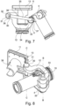
- Fig. 1 to 4 shows a schematic perspective view of a coupler 1 according to the invention.
- the coupler 1 is for a rail vehicle.
- the coupler 1 will be attached to an end of one rail vehicle.
- the coupler 1 each comprises
- the couplers 1 further comprise a crash plate 11 attached to the forward end 7 of the rear portion 6 by way of a crash plate joint 30, the crash plate joint 30 being configured to allow the crash plate 11 to pivot in relation to the rear portion 6 about an pivot axis C from an operational position (see e.g. Fig. 1 ) in which the crash plate 11 is arranged in front of the rear portion 6 to a pivoted position (see e.g. Fig. 2 ) in which the crash plate 11 is pivoted about the pivot axis C to a side position.
- the pivot axis C of the crash plate joint 30 is parallel to the pivot axis B of the joint 10, both pivot axis B and pivot axis C are each orientated spaced apart from and perpendicular to the longitudinal axis A.
- the pivot movement of the crash plate 11 about the pivot axis C is synchronized to the pivot movement of the front portion 2 about the pivot axis B.
- the crash plate joint 30 has a pin 31 with an endsurface 32, which endsurface 32 is arranged perpendicular to the pivot axis C and the joint 10 has a pin 33 with an endsurface 34, which endsurface 34 is arranged perpendicular to the pivot axis B and whereby a bar 35 is provided and
- a rotation of the pin 33 about the pivot axis B leads to the further end 37 to rotate around the pivot axis B along a arc-shaped path.
- This movement of the further end 37 will translate into a movement of the end 36, which will rotate around the pivot axis C along an arc-shaped path leading to a rotation of the pin 31 about the pivot axis C.
- a rotation of the pin 33 can be translated into a rotation of the pin 31.
- a tube 38 is provided on the back of the crash plate 11, whereby an end of the tube 38 rests against a crash plate holder 12 when the crash plate 11 is in the operational position.
- the crash plate 11 is attached to the rear portion 6 by way of a crash plate holder 12 that is mounted on the forward end 7 of the rear portion 6.
- the joint 10 and the crash plate joint 30 are parts of the crash plate holder 12.
- crash plate 11 arranged on a crash plate holder 12, said crash plate 11 having a substantially vertical front surface 13 that is arranged in front of the front portion 2, the rear portion 6 and the joint 10 when the front portion 2 is in the pivoted position (see e. g. Fig. 4 ).
- the crash plate 11 has an anti-climbing surface arranged on the vertical front surface 13.
- the vertical front surface 13 of the crash plate is flat.
- the angle is less than 90 °, preferably less than 45 °.
- the pivot anchor 9 comprises an energy dissipating element in form of shear out bolts 17.
- the shear out bolt 17 connects a plate 18 of the pivot anchor 9 with a frame plate 19.
- the frame plate 19 is intended for being connected to the underframe of a car of a rail vehicle.
- the shear out bolts 17 will be destructed, if a force of a certain force level is applied to them. Destruction of the shear out bolts 17 also destroys the connection between the plate 18 and the frame plate 19 and sets the frame plate 19 free to move relative to the plate 18.
- Fig. 1 and 2 show a guide rail 39 that forms part of the underframe of the vehicle.
- the front portion 2 can have a guide wheel 40 that is picked up by the guide rail 39 when the front portion 2 is in the pivoted position (see e.g. Fig. 1 ).
- the coupler 1 can have a drive, for example a pneumatic or hydraulic cylinder 41 that is attached with one end to the rear portion 6 and attached with its other end to a lever 42, said lever 42 being connected to the pin 33 of the joint 10. Expansion or retraction of the cylinder 41 will lead to the end that is attached to the lever 42 and will lead to the lever 42 to rotate about the pivot axis B thereby turning the pin 33 of the joint 10 about the pivot axis B. This rotation will move the front portion 2 from the operational position ( Fig. 2 ) to the pivoted position ( Fig. 1 ). Given the synchronization of the rotation of the pin 33 with the pin 31, this rotation will also lead to a rotation of the pin 31 and will lead to the crash plate 11 being moved from the operational position ( Fig. 1 ) to the pivoted position ( Fig. 2 ).
- a drive for example a pneumatic or hydraulic cylinder 41 that is attached with one end to the rear portion 6 and attached with its other end to a lever 42, said lever 42 being connected to the
Landscapes
- Engineering & Computer Science (AREA)
- Mechanical Engineering (AREA)
- Vibration Dampers (AREA)
- Body Structure For Vehicles (AREA)
Claims (11)
- Attelage (1) pour véhicule ferroviaire, l'attelage comprenant :- une portion avant (2) présentant une extrémité avant (3) et une extrémité arrière (4), et une tête d'attelage (5) agencée sur l'extrémité avant (3) de la portion avant (2) ;- une portion arrière (6) présentant une extrémité avant (7) et une extrémité arrière (8) et s'étendant le long d'un axe longitudinal (A) allant de l'extrémité arrière (8) à l'extrémité avant (7) ;- un ancrage pivotant (9) agencé sur une extrémité arrière (8) de la portion arrière (6), l'ancrage pivotant (9) étant configuré pour être attaché sur une voiture d'un véhicule ferroviaire, et- un joint (10) pour raccorder une extrémité arrière (4) de la portion avant (2) à l'extrémité avant (7) de la portion arrière (6), le joint (10) étant configuré pour permettre à la portion avant (2) de pivoter par rapport à la portion arrière (6) autour d'un axe de pivotement (B), lequel est perpendiculaire à l'axe longitudinal (A) d'une position de fonctionnement, où la portion avant (2) et la portion arrière (6) sont alignées de sorte que la portion avant (2) s'étend dans une direction vers l'avant à partir de la portion arrière (6), vers une position pivotée, où la portion avant (2) est pivotée autour de l'axe de pivotement (B), de sorte que la portion vers l'avant (2) s'étend suivant un angle à partir de la portion arrière (6),
caractérisé en ce que
l'attelage (1) comprend en outre une plaque tampon (11) attachée sur l'extrémité avant (7) de la portion arrière (6) par le biais d'un joint de plaque tampon (30), le joint de plaque tampon (30) étant configuré pour permettre à la plaque tampon (11) de pivoter par rapport à la portion arrière (6) autour d'un axe de pivotement (C) d'une position de fonctionnement, où la plaque tampon (11) est agencée devant la portion arrière (6), vers une position pivotée, où la plaque tampon (11) est pivotée autour de l'axe de pivotement (C) vers une position latérale. - Attelage selon la revendication 1, dans lequel la portion arrière (6) est attachée d'une manière ne permettant pas le pivotement sur l'ancrage de pivotement (9).
- Attelage selon la revendication 1 ou 2, dans lequel l'axe de pivotement (C) du joint de plaque tampon (30) est parallèle à l'axe de pivotement (B) du joint (10).
- Attelage selon l'une quelconque des revendications 1 à 3, dans lequel le mouvement pivotant de la plaque tampon (11) autour de l'axe de pivotement (C) est synchronisé sur le mouvement pivotant de la portion avant (2) autour de l'axe de pivotement (B).
- Attelage selon la revendication 4, dans lequel le joint de plaque tampon (30) présente une broche (31) présentant une surface d'extrémité (32), laquelle surface d'extrémité (32) est agencée perpendiculairement à l'axe de pivotement (C), et le joint (10) présente une broche (33) avec une surface d'extrémité (34), laquelle surface d'extrémité (34) est agencée perpendiculairement à l'axe de pivotement (B), et en sachant qu'une barre (35) est prévue, et que- une extrémité (36) de la barre (35) est attachée d'une manière permettant la rotation à la surface d'extrémité (32) de la broche (31) du joint de plaque tampon (30), en sachant que l'attache est excentrée sur la surface d'extrémité (32), et- une extrémité supplémentaire (37) de la barre (35) est attachée d'une manière permettant la rotation sur la surface d'extrémité (34) de la broche (33) du joint (10), en sachant que l'attache est excentrée sur la surface d'extrémité (34).
- Attelage selon l'une quelconque des revendications 1 à 5, dans lequel un tube (38) est prévu sur le dos de la plaque tampon (11), en sachant qu'une extrémité du tube (38) repose contre l'extrémité avant (7) de la portion arrière (6) lorsque la plaque tampon (11) est dans la position de fonctionnement.
- Attelage selon l'une quelconque des revendications précédentes, dans lequel la plaque tampon (11) présente une surface anti-montée.
- Attelage selon l'une quelconque des revendications précédentes, dans lequel au moins une partie de la plaque tampon (11) comprend un dispositif d'alignement horizontal pour empêcher le déplacement dans une direction horizontale d'un attelage homologue.
- Attelage selon l'une quelconque des revendications précédentes, dans lequel l'angle est inférieur à 90 °, et est de préférence inférieur à 45 °.
- Attelage selon l'une quelconque des revendications précédentes, dans lequel la portion arrière et/ou l'ancrage de pivotement comprend un élément de dissipation d'énergie (17), lequel sera détruit, si une force d'un certain niveau de force est appliquée à l'élément de dissipation d'énergie (17).
- Véhicule ferroviaire doté d'un attelage selon l'une quelconque des revendications 1 à 10 attaché sur celui-ci.
Priority Applications (3)
| Application Number | Priority Date | Filing Date | Title |
|---|---|---|---|
| EP21213243.5A EP4194309B1 (fr) | 2021-12-08 | 2021-12-08 | Coupleur de véhicule ferroviaire et véhicule ferroviaire doté d'un coupleur |
| US18/076,973 US12623699B2 (en) | 2021-12-08 | 2022-12-07 | Coupler for a rail vehicle and rail vehicle with a coupler |
| CN202211572934.3A CN116238557A (zh) | 2021-12-08 | 2022-12-08 | 用于轨道车辆的联接器和具有联接器的轨道车辆 |
Applications Claiming Priority (1)
| Application Number | Priority Date | Filing Date | Title |
|---|---|---|---|
| EP21213243.5A EP4194309B1 (fr) | 2021-12-08 | 2021-12-08 | Coupleur de véhicule ferroviaire et véhicule ferroviaire doté d'un coupleur |
Publications (3)
| Publication Number | Publication Date |
|---|---|
| EP4194309A1 EP4194309A1 (fr) | 2023-06-14 |
| EP4194309C0 EP4194309C0 (fr) | 2024-02-28 |
| EP4194309B1 true EP4194309B1 (fr) | 2024-02-28 |
Family
ID=78827831
Family Applications (1)
| Application Number | Title | Priority Date | Filing Date |
|---|---|---|---|
| EP21213243.5A Active EP4194309B1 (fr) | 2021-12-08 | 2021-12-08 | Coupleur de véhicule ferroviaire et véhicule ferroviaire doté d'un coupleur |
Country Status (3)
| Country | Link |
|---|---|
| US (1) | US12623699B2 (fr) |
| EP (1) | EP4194309B1 (fr) |
| CN (1) | CN116238557A (fr) |
Families Citing this family (2)
| Publication number | Priority date | Publication date | Assignee | Title |
|---|---|---|---|---|
| CN115697811A (zh) * | 2020-06-08 | 2023-02-03 | 德尔纳库普勒斯股份公司 | 用于轨道车辆的联接器和具有联接器的轨道车辆 |
| EP4194309B1 (fr) | 2021-12-08 | 2024-02-28 | Dellner Couplers AB | Coupleur de véhicule ferroviaire et véhicule ferroviaire doté d'un coupleur |
Family Cites Families (23)
| Publication number | Priority date | Publication date | Assignee | Title |
|---|---|---|---|---|
| BE386322A (fr) | 1931-05-01 | |||
| US2287954A (en) * | 1940-03-15 | 1942-06-30 | Buckeye Steel Castings Co | Locomotive pilot coupler structure |
| US2381603A (en) | 1943-07-24 | 1945-08-07 | Ohio Brass Co | Car coupling equipment |
| CH376956A (de) * | 1960-02-19 | 1964-04-30 | Inventio Ag | Kupplung für Eisenbahnwagen |
| US3871529A (en) | 1974-03-22 | 1975-03-18 | Halliburton Co | Integral coupler centering device |
| JP2585385B2 (ja) * | 1988-08-05 | 1997-02-26 | 株式会社日立製作所 | 車両用連結装置 |
| DE4006811A1 (de) | 1990-03-05 | 1991-09-12 | Bergische Stahlindustrie | Mittelpufferkupplung mit sicherheitseinrichtung |
| DE19921510B4 (de) | 1999-05-10 | 2009-07-23 | Knorr-Bremse Systeme für Schienenfahrzeuge GmbH | Abstützvorrichtung für eine automatische Zugkupplung |
| US6499613B1 (en) | 1999-12-30 | 2002-12-31 | Westinghouse Air Brake Company | Coupler with extended emergency release and towing feature |
| ES2300829T3 (es) * | 2003-09-19 | 2008-06-16 | Siemens Transportation Systems Inc. | Sistema de proteccion de impacto integrado. |
| ES2334170T3 (es) | 2007-04-25 | 2010-03-05 | Voith Patent Gmbh | Acoplamiento automatico articulado. |
| US8960464B2 (en) | 2011-04-08 | 2015-02-24 | Wabtec Holding Corp. | Coupler support mechanism |
| US9758182B2 (en) | 2013-03-22 | 2017-09-12 | Wabtec Holding Corp. | Automated coupler positioning device |
| GB2565504B (en) | 2016-10-21 | 2019-08-07 | Crrc Qingdao Sifang Co Ltd | Coupling assembly and rail vehicle having same |
| DE102016125087A1 (de) | 2016-12-21 | 2018-06-21 | Voith Patent Gmbh | Kupplungsanordnung, insbesondere für ein Schienenfahrzeug |
| CN210391159U (zh) | 2019-09-09 | 2020-04-24 | 中车青岛四方车辆研究所有限公司 | 折叠车钩和车辆 |
| EP3992054B1 (fr) * | 2019-09-09 | 2023-07-19 | Crrc Qingdao Sifang Rolling Stock Research Institute Co., Ltd. | Coupleur de véhicule pliable et véhicule |
| CN212047325U (zh) | 2019-12-06 | 2020-12-01 | 株洲春华实业有限责任公司 | 一种空中轨道车辆自动连接车钩的自动追踪导向装置 |
| US11691468B2 (en) | 2020-05-05 | 2023-07-04 | Deere & Company | Equal angle hitch |
| CN115697811A (zh) | 2020-06-08 | 2023-02-03 | 德尔纳库普勒斯股份公司 | 用于轨道车辆的联接器和具有联接器的轨道车辆 |
| GB2600408B (en) | 2020-10-27 | 2024-04-03 | Ritchie Kinghorn John | Extendable coupler |
| EP4194309B1 (fr) | 2021-12-08 | 2024-02-28 | Dellner Couplers AB | Coupleur de véhicule ferroviaire et véhicule ferroviaire doté d'un coupleur |
| SE545564C2 (en) | 2022-03-03 | 2023-10-24 | Dellner Couplers Ab | Coupler for a railway vehicle with a biasing device, and method for overhauling a coupler |
-
2021
- 2021-12-08 EP EP21213243.5A patent/EP4194309B1/fr active Active
-
2022
- 2022-12-07 US US18/076,973 patent/US12623699B2/en active Active
- 2022-12-08 CN CN202211572934.3A patent/CN116238557A/zh active Pending
Also Published As
| Publication number | Publication date |
|---|---|
| EP4194309A1 (fr) | 2023-06-14 |
| US20230202537A1 (en) | 2023-06-29 |
| EP4194309C0 (fr) | 2024-02-28 |
| US12623699B2 (en) | 2026-05-12 |
| CN116238557A (zh) | 2023-06-09 |
Similar Documents
| Publication | Publication Date | Title |
|---|---|---|
| US12623699B2 (en) | Coupler for a rail vehicle and rail vehicle with a coupler | |
| US6470626B2 (en) | Gate release mechanism with detent and plunger, and gate incorporating same | |
| US8240618B1 (en) | Multiple direction railroad gate release mechanism | |
| US20230211815A1 (en) | Coupler for a rail vehicle and rail vehicle with a coupler | |
| US7963054B2 (en) | Coupling configuration with a device for connecting energy transmission lines | |
| EP3437962B1 (fr) | Appareil de positionnement et de direction de roue de véhicule | |
| US7913865B2 (en) | Support device | |
| US20110147331A1 (en) | Jib stowing device for jib crane vehicle | |
| EP1436465B1 (fr) | Amortisseur de choc monte sur un vehicule | |
| GB2289491A (en) | Retractable post assembly | |
| EP3807140A1 (fr) | Agencement d'attelage de train à module d'expansion axiale | |
| US6068329A (en) | Rear-impact underride protector | |
| US5000499A (en) | Deflectable vehicle bumper | |
| EP3922531B1 (fr) | Accouplement pour véhicule ferroviaire et véhicule ferroviaire avec ledit accouplement | |
| JP3669035B2 (ja) | シールド掘進機のセグメント組立装置 | |
| CN106494451B (zh) | 车钩组件及具有该车钩组件的轨道车辆 | |
| EP3957540B1 (fr) | Véhicule ferroviaire et ensemble freinage de celui-ci | |
| CN210391169U (zh) | 轨道限界检测设备 | |
| US2411735A (en) | Guard for angle cocks for train lines | |
| CN215436162U (zh) | 一种带交通疏导功能的防撞缓冲车 | |
| US5941549A (en) | Fifth wheel kingpin deflector and catcher | |
| CN223459330U (zh) | 一种可变径钻头 | |
| CN224172397U (zh) | 一种电动搬运车的辅助支撑结构 | |
| CN117773444B (zh) | 一种车钩安装座高效焊接装置 | |
| EP1776265B1 (fr) | Attelage a tampon central pour vehicules ferroviaires pivotant entre une position operationnelle et une position inoperationnelle |
Legal Events
| Date | Code | Title | Description |
|---|---|---|---|
| PUAI | Public reference made under article 153(3) epc to a published international application that has entered the european phase |
Free format text: ORIGINAL CODE: 0009012 |
|
| STAA | Information on the status of an ep patent application or granted ep patent |
Free format text: STATUS: THE APPLICATION HAS BEEN PUBLISHED |
|
| AK | Designated contracting states |
Kind code of ref document: A1 Designated state(s): AL AT BE BG CH CY CZ DE DK EE ES FI FR GB GR HR HU IE IS IT LI LT LU LV MC MK MT NL NO PL PT RO RS SE SI SK SM TR |
|
| STAA | Information on the status of an ep patent application or granted ep patent |
Free format text: STATUS: REQUEST FOR EXAMINATION WAS MADE |
|
| 17P | Request for examination filed |
Effective date: 20230706 |
|
| RBV | Designated contracting states (corrected) |
Designated state(s): AL AT BE BG CH CY CZ DE DK EE ES FI FR GB GR HR HU IE IS IT LI LT LU LV MC MK MT NL NO PL PT RO RS SE SI SK SM TR |
|
| GRAP | Despatch of communication of intention to grant a patent |
Free format text: ORIGINAL CODE: EPIDOSNIGR1 |
|
| STAA | Information on the status of an ep patent application or granted ep patent |
Free format text: STATUS: GRANT OF PATENT IS INTENDED |
|
| INTG | Intention to grant announced |
Effective date: 20231114 |
|
| GRAS | Grant fee paid |
Free format text: ORIGINAL CODE: EPIDOSNIGR3 |
|
| GRAA | (expected) grant |
Free format text: ORIGINAL CODE: 0009210 |
|
| STAA | Information on the status of an ep patent application or granted ep patent |
Free format text: STATUS: THE PATENT HAS BEEN GRANTED |
|
| AK | Designated contracting states |
Kind code of ref document: B1 Designated state(s): AL AT BE BG CH CY CZ DE DK EE ES FI FR GB GR HR HU IE IS IT LI LT LU LV MC MK MT NL NO PL PT RO RS SE SI SK SM TR |
|
| REG | Reference to a national code |
Ref country code: GB Ref legal event code: FG4D |
|
| REG | Reference to a national code |
Ref country code: CH Ref legal event code: EP |
|
| REG | Reference to a national code |
Ref country code: DE Ref legal event code: R096 Ref document number: 602021009813 Country of ref document: DE |
|
| REG | Reference to a national code |
Ref country code: IE Ref legal event code: FG4D |
|
| U01 | Request for unitary effect filed |
Effective date: 20240228 |
|
| U07 | Unitary effect registered |
Designated state(s): AT BE BG DE DK EE FI FR IT LT LU LV MT NL PT SE SI Effective date: 20240305 |
|
| REG | Reference to a national code |
Ref country code: LT Ref legal event code: MG9D |
|
| PG25 | Lapsed in a contracting state [announced via postgrant information from national office to epo] |
Ref country code: IS Free format text: LAPSE BECAUSE OF FAILURE TO SUBMIT A TRANSLATION OF THE DESCRIPTION OR TO PAY THE FEE WITHIN THE PRESCRIBED TIME-LIMIT Effective date: 20240628 |
|
| PG25 | Lapsed in a contracting state [announced via postgrant information from national office to epo] |
Ref country code: GR Free format text: LAPSE BECAUSE OF FAILURE TO SUBMIT A TRANSLATION OF THE DESCRIPTION OR TO PAY THE FEE WITHIN THE PRESCRIBED TIME-LIMIT Effective date: 20240529 |
|
| PG25 | Lapsed in a contracting state [announced via postgrant information from national office to epo] |
Ref country code: RS Free format text: LAPSE BECAUSE OF FAILURE TO SUBMIT A TRANSLATION OF THE DESCRIPTION OR TO PAY THE FEE WITHIN THE PRESCRIBED TIME-LIMIT Effective date: 20240528 Ref country code: HR Free format text: LAPSE BECAUSE OF FAILURE TO SUBMIT A TRANSLATION OF THE DESCRIPTION OR TO PAY THE FEE WITHIN THE PRESCRIBED TIME-LIMIT Effective date: 20240228 |
|
| PG25 | Lapsed in a contracting state [announced via postgrant information from national office to epo] |
Ref country code: ES Free format text: LAPSE BECAUSE OF FAILURE TO SUBMIT A TRANSLATION OF THE DESCRIPTION OR TO PAY THE FEE WITHIN THE PRESCRIBED TIME-LIMIT Effective date: 20240228 |
|
| PG25 | Lapsed in a contracting state [announced via postgrant information from national office to epo] |
Ref country code: RS Free format text: LAPSE BECAUSE OF FAILURE TO SUBMIT A TRANSLATION OF THE DESCRIPTION OR TO PAY THE FEE WITHIN THE PRESCRIBED TIME-LIMIT Effective date: 20240528 Ref country code: NO Free format text: LAPSE BECAUSE OF FAILURE TO SUBMIT A TRANSLATION OF THE DESCRIPTION OR TO PAY THE FEE WITHIN THE PRESCRIBED TIME-LIMIT Effective date: 20240528 Ref country code: IS Free format text: LAPSE BECAUSE OF FAILURE TO SUBMIT A TRANSLATION OF THE DESCRIPTION OR TO PAY THE FEE WITHIN THE PRESCRIBED TIME-LIMIT Effective date: 20240628 Ref country code: HR Free format text: LAPSE BECAUSE OF FAILURE TO SUBMIT A TRANSLATION OF THE DESCRIPTION OR TO PAY THE FEE WITHIN THE PRESCRIBED TIME-LIMIT Effective date: 20240228 Ref country code: GR Free format text: LAPSE BECAUSE OF FAILURE TO SUBMIT A TRANSLATION OF THE DESCRIPTION OR TO PAY THE FEE WITHIN THE PRESCRIBED TIME-LIMIT Effective date: 20240529 Ref country code: ES Free format text: LAPSE BECAUSE OF FAILURE TO SUBMIT A TRANSLATION OF THE DESCRIPTION OR TO PAY THE FEE WITHIN THE PRESCRIBED TIME-LIMIT Effective date: 20240228 |
|
| PG25 | Lapsed in a contracting state [announced via postgrant information from national office to epo] |
Ref country code: PL Free format text: LAPSE BECAUSE OF FAILURE TO SUBMIT A TRANSLATION OF THE DESCRIPTION OR TO PAY THE FEE WITHIN THE PRESCRIBED TIME-LIMIT Effective date: 20240228 |
|
| PG25 | Lapsed in a contracting state [announced via postgrant information from national office to epo] |
Ref country code: PL Free format text: LAPSE BECAUSE OF FAILURE TO SUBMIT A TRANSLATION OF THE DESCRIPTION OR TO PAY THE FEE WITHIN THE PRESCRIBED TIME-LIMIT Effective date: 20240228 |
|
| PG25 | Lapsed in a contracting state [announced via postgrant information from national office to epo] |
Ref country code: SM Free format text: LAPSE BECAUSE OF FAILURE TO SUBMIT A TRANSLATION OF THE DESCRIPTION OR TO PAY THE FEE WITHIN THE PRESCRIBED TIME-LIMIT Effective date: 20240228 |
|
| PG25 | Lapsed in a contracting state [announced via postgrant information from national office to epo] |
Ref country code: CZ Free format text: LAPSE BECAUSE OF FAILURE TO SUBMIT A TRANSLATION OF THE DESCRIPTION OR TO PAY THE FEE WITHIN THE PRESCRIBED TIME-LIMIT Effective date: 20240228 |
|
| PG25 | Lapsed in a contracting state [announced via postgrant information from national office to epo] |
Ref country code: SK Free format text: LAPSE BECAUSE OF FAILURE TO SUBMIT A TRANSLATION OF THE DESCRIPTION OR TO PAY THE FEE WITHIN THE PRESCRIBED TIME-LIMIT Effective date: 20240228 |
|
| PG25 | Lapsed in a contracting state [announced via postgrant information from national office to epo] |
Ref country code: SM Free format text: LAPSE BECAUSE OF FAILURE TO SUBMIT A TRANSLATION OF THE DESCRIPTION OR TO PAY THE FEE WITHIN THE PRESCRIBED TIME-LIMIT Effective date: 20240228 Ref country code: SK Free format text: LAPSE BECAUSE OF FAILURE TO SUBMIT A TRANSLATION OF THE DESCRIPTION OR TO PAY THE FEE WITHIN THE PRESCRIBED TIME-LIMIT Effective date: 20240228 Ref country code: RO Free format text: LAPSE BECAUSE OF FAILURE TO SUBMIT A TRANSLATION OF THE DESCRIPTION OR TO PAY THE FEE WITHIN THE PRESCRIBED TIME-LIMIT Effective date: 20240228 Ref country code: CZ Free format text: LAPSE BECAUSE OF FAILURE TO SUBMIT A TRANSLATION OF THE DESCRIPTION OR TO PAY THE FEE WITHIN THE PRESCRIBED TIME-LIMIT Effective date: 20240228 |
|
| REG | Reference to a national code |
Ref country code: DE Ref legal event code: R097 Ref document number: 602021009813 Country of ref document: DE |
|
| U20 | Renewal fee for the european patent with unitary effect paid |
Year of fee payment: 4 Effective date: 20241122 |
|
| PLBE | No opposition filed within time limit |
Free format text: ORIGINAL CODE: 0009261 |
|
| STAA | Information on the status of an ep patent application or granted ep patent |
Free format text: STATUS: NO OPPOSITION FILED WITHIN TIME LIMIT |
|
| 26N | No opposition filed |
Effective date: 20241129 |
|
| PG25 | Lapsed in a contracting state [announced via postgrant information from national office to epo] |
Ref country code: MC Free format text: LAPSE BECAUSE OF FAILURE TO SUBMIT A TRANSLATION OF THE DESCRIPTION OR TO PAY THE FEE WITHIN THE PRESCRIBED TIME-LIMIT Effective date: 20240228 |
|
| REG | Reference to a national code |
Ref country code: CH Ref legal event code: PL |
|
| PG25 | Lapsed in a contracting state [announced via postgrant information from national office to epo] |
Ref country code: CH Free format text: LAPSE BECAUSE OF NON-PAYMENT OF DUE FEES Effective date: 20241231 |
|
| PG25 | Lapsed in a contracting state [announced via postgrant information from national office to epo] |
Ref country code: IE Free format text: LAPSE BECAUSE OF NON-PAYMENT OF DUE FEES Effective date: 20241208 |
|
| PGFP | Annual fee paid to national office [announced via postgrant information from national office to epo] |
Ref country code: GB Payment date: 20251218 Year of fee payment: 5 |
|
| U20 | Renewal fee for the european patent with unitary effect paid |
Year of fee payment: 5 Effective date: 20251218 |
|
| PG25 | Lapsed in a contracting state [announced via postgrant information from national office to epo] |
Ref country code: CY Free format text: LAPSE BECAUSE OF FAILURE TO SUBMIT A TRANSLATION OF THE DESCRIPTION OR TO PAY THE FEE WITHIN THE PRESCRIBED TIME-LIMIT Effective date: 20240228 |