EP4194704A1 - Agencement d'éjecteur de jet, système et utilisation associés et son procédé de fonctionnement - Google Patents
Agencement d'éjecteur de jet, système et utilisation associés et son procédé de fonctionnement Download PDFInfo
- Publication number
- EP4194704A1 EP4194704A1 EP21214101.4A EP21214101A EP4194704A1 EP 4194704 A1 EP4194704 A1 EP 4194704A1 EP 21214101 A EP21214101 A EP 21214101A EP 4194704 A1 EP4194704 A1 EP 4194704A1
- Authority
- EP
- European Patent Office
- Prior art keywords
- fluid
- container
- hollow tube
- jet ejector
- motive fluid
- Prior art date
- Legal status (The legal status is an assumption and is not a legal conclusion. Google has not performed a legal analysis and makes no representation as to the accuracy of the status listed.)
- Withdrawn
Links
Images

Classifications
-
- B—PERFORMING OPERATIONS; TRANSPORTING
- B05—SPRAYING OR ATOMISING IN GENERAL; APPLYING FLUENT MATERIALS TO SURFACES, IN GENERAL
- B05B—SPRAYING APPARATUS; ATOMISING APPARATUS; NOZZLES
- B05B7/00—Spraying apparatus for discharge of liquids or other fluent materials from two or more sources, e.g. of liquid and air, of powder and gas
- B05B7/0081—Apparatus supplied with low pressure gas, e.g. "hvlp"-guns; air supplied by a fan
- B05B7/0087—Atmospheric air being sucked by a gas stream, generally flowing through a venturi, at a location upstream or inside the spraying apparatus
-
- F—MECHANICAL ENGINEERING; LIGHTING; HEATING; WEAPONS; BLASTING
- F04—POSITIVE - DISPLACEMENT MACHINES FOR LIQUIDS; PUMPS FOR LIQUIDS OR ELASTIC FLUIDS
- F04F—PUMPING OF FLUID BY DIRECT CONTACT OF ANOTHER FLUID OR BY USING INERTIA OF FLUID TO BE PUMPED; SIPHONS
- F04F5/00—Jet pumps, i.e. devices in which flow is induced by pressure drop caused by velocity of another fluid flow
- F04F5/44—Component parts, details, or accessories not provided for in, or of interest apart from, groups F04F5/02 - F04F5/42
- F04F5/46—Arrangements of nozzles
- F04F5/463—Arrangements of nozzles with provisions for mixing
-
- F—MECHANICAL ENGINEERING; LIGHTING; HEATING; WEAPONS; BLASTING
- F04—POSITIVE - DISPLACEMENT MACHINES FOR LIQUIDS; PUMPS FOR LIQUIDS OR ELASTIC FLUIDS
- F04F—PUMPING OF FLUID BY DIRECT CONTACT OF ANOTHER FLUID OR BY USING INERTIA OF FLUID TO BE PUMPED; SIPHONS
- F04F5/00—Jet pumps, i.e. devices in which flow is induced by pressure drop caused by velocity of another fluid flow
- F04F5/02—Jet pumps, i.e. devices in which flow is induced by pressure drop caused by velocity of another fluid flow the inducing fluid being liquid
- F04F5/04—Jet pumps, i.e. devices in which flow is induced by pressure drop caused by velocity of another fluid flow the inducing fluid being liquid displacing elastic fluids
-
- F—MECHANICAL ENGINEERING; LIGHTING; HEATING; WEAPONS; BLASTING
- F04—POSITIVE - DISPLACEMENT MACHINES FOR LIQUIDS; PUMPS FOR LIQUIDS OR ELASTIC FLUIDS
- F04F—PUMPING OF FLUID BY DIRECT CONTACT OF ANOTHER FLUID OR BY USING INERTIA OF FLUID TO BE PUMPED; SIPHONS
- F04F5/00—Jet pumps, i.e. devices in which flow is induced by pressure drop caused by velocity of another fluid flow
- F04F5/02—Jet pumps, i.e. devices in which flow is induced by pressure drop caused by velocity of another fluid flow the inducing fluid being liquid
- F04F5/10—Jet pumps, i.e. devices in which flow is induced by pressure drop caused by velocity of another fluid flow the inducing fluid being liquid displacing liquids, e.g. containing solids, or liquids and elastic fluids
-
- F—MECHANICAL ENGINEERING; LIGHTING; HEATING; WEAPONS; BLASTING
- F04—POSITIVE - DISPLACEMENT MACHINES FOR LIQUIDS; PUMPS FOR LIQUIDS OR ELASTIC FLUIDS
- F04F—PUMPING OF FLUID BY DIRECT CONTACT OF ANOTHER FLUID OR BY USING INERTIA OF FLUID TO BE PUMPED; SIPHONS
- F04F5/00—Jet pumps, i.e. devices in which flow is induced by pressure drop caused by velocity of another fluid flow
- F04F5/14—Jet pumps, i.e. devices in which flow is induced by pressure drop caused by velocity of another fluid flow the inducing fluid being elastic fluid
- F04F5/16—Jet pumps, i.e. devices in which flow is induced by pressure drop caused by velocity of another fluid flow the inducing fluid being elastic fluid displacing elastic fluids
-
- F—MECHANICAL ENGINEERING; LIGHTING; HEATING; WEAPONS; BLASTING
- F04—POSITIVE - DISPLACEMENT MACHINES FOR LIQUIDS; PUMPS FOR LIQUIDS OR ELASTIC FLUIDS
- F04F—PUMPING OF FLUID BY DIRECT CONTACT OF ANOTHER FLUID OR BY USING INERTIA OF FLUID TO BE PUMPED; SIPHONS
- F04F5/00—Jet pumps, i.e. devices in which flow is induced by pressure drop caused by velocity of another fluid flow
- F04F5/14—Jet pumps, i.e. devices in which flow is induced by pressure drop caused by velocity of another fluid flow the inducing fluid being elastic fluid
- F04F5/24—Jet pumps, i.e. devices in which flow is induced by pressure drop caused by velocity of another fluid flow the inducing fluid being elastic fluid displacing liquids, e.g. containing solids, or liquids and elastic fluids
-
- F—MECHANICAL ENGINEERING; LIGHTING; HEATING; WEAPONS; BLASTING
- F04—POSITIVE - DISPLACEMENT MACHINES FOR LIQUIDS; PUMPS FOR LIQUIDS OR ELASTIC FLUIDS
- F04F—PUMPING OF FLUID BY DIRECT CONTACT OF ANOTHER FLUID OR BY USING INERTIA OF FLUID TO BE PUMPED; SIPHONS
- F04F5/00—Jet pumps, i.e. devices in which flow is induced by pressure drop caused by velocity of another fluid flow
- F04F5/42—Jet pumps, i.e. devices in which flow is induced by pressure drop caused by velocity of another fluid flow characterised by the input flow of inducing fluid medium being radial or tangential to output flow
-
- F—MECHANICAL ENGINEERING; LIGHTING; HEATING; WEAPONS; BLASTING
- F04—POSITIVE - DISPLACEMENT MACHINES FOR LIQUIDS; PUMPS FOR LIQUIDS OR ELASTIC FLUIDS
- F04F—PUMPING OF FLUID BY DIRECT CONTACT OF ANOTHER FLUID OR BY USING INERTIA OF FLUID TO BE PUMPED; SIPHONS
- F04F5/00—Jet pumps, i.e. devices in which flow is induced by pressure drop caused by velocity of another fluid flow
- F04F5/44—Component parts, details, or accessories not provided for in, or of interest apart from, groups F04F5/02 - F04F5/42
- F04F5/48—Control
Definitions
- the present disclosure relates to the field of jet ejectors, their method of operation and their uses.
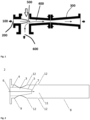
- FIG. 1 showing a conventional ejector and its basic elements.
- An ejector is a type of vacuum pump, which produces vacuum by means of the Venturi effect.
- a working fluid liquid or gaseous
- a jet nozzle 200
- a tube 300
- expands in cross-sectional area 400
- the fluid leaving the jet is flowing at a high velocity which due to Bernoulli's principle results in it having underpressure, thus generating a vacuum.
- the outer tube then elongates into a mixing section (500) where the high velocity working fluid mixes with the fluid that is drawn in by the vacuum (600), imparting enough velocity for it to be ejected, the tube then typically expands in order to decrease the velocity of the ejected stream, allowing the pressure to smoothly increase to the external pressure.
- the strength of the vacuum produced depends on the velocity and shape of the fluid jet and the shape of the constriction and mixing sections, but if a liquid is used as the working fluid the strength of the vacuum produced is limited by the vapor pressure of the liquid (for example in the case of water, 3.2 kPa or 0.46 psi or 32 mbar at 25 °C or 77 °F). If a gas is used, however, this restriction does not exist.
- vacuum ejectors can be significantly more compact than a self-powered vacuum pump of the same capacity.
- a pipe reactor is an example of a jet ejector.
- EP0272974B1 (Grande Paroisse S.A., 1993 ) discloses a reactor allowing an improved reaction between ammonia and acids.
- the improved tubular reactor incorporates a convergent-divergent member or a convergent member at the exit of the zone for introducing reactants and a convergent-divergent member or a convergent member at the exit of the reaction zone just before the exit nozzle for the finished products.
- the size, and hence the footprint, of the reactor is increased.
- the reaction is carried out under pressure and some heat is produced by the reaction of the ammonia with the acid and vaporizes the water in the reactor itself. If the separator at the outlet of the reactor operates at atmospheric pressure, additional moisture content of the product flashes off at the discharge point of the pipe where the pressure is about 1bara. This means that temperature within the reactor is higher than the temperature of the solution at the discharge of the pipe. Considering that, in such systems, a safety temperature is to be maintained within the reactor, the concentration of the acid in the reactor or the temperature at which the acid is fed in the reactor are to be controlled and kept sufficiently low, thereby limiting the amount of heat, and therefore energy, provided by the reaction. Said otherwise, the safety temperature required on the product imposes restrictions on the operating conditions.
- the pressure inside the reactor depends on the flow rate, only within a certain operating pressure range is the temperature in the pipe reactor safe, such that the pressure range at which the reactor can be operated is limited. Moreover as the reaction inside the reactor takes place in a confined space, in order to prevent any pressure build-up, controlling the operating pressure within a defined, safe range is critical.
- GB2026611 discloses an ejector pump to pump liquid out of an enclosed space and simultaneously to maintain a vacuum within this enclosed space.
- a suction connection 2 for removal of gaseous media is disposed adjacent to a propellant nozzle 7 for entry of a propellant jet of liquid so that the gaseous media is drawn into a premixing tube 8, the outlet of the premixing tube 8 communicates with a mixing chamber 4 also in communication with a suction connection 9 for the liquid, whereby the liquid is drawn off at a location well downstream of the suction connection for the gaseous media.
- the controlling factor becomes the partial pressure created by the liquid employed for the propellant jet and this may be chosen accordingly.
- the suction connection 2 is the basis of Koerting nozzles used in Koerting's liquid jet mixing nozzles and tank mixing systems. Those systems, however, are disclosed as mixing systems and involve the mixing of two components only.
- One goal of this disclosure is to provide a reactive jet ejector arrangement, suitable for reacting components and also mixing those components with their products, such that an optimally complete reaction of the reactants is achieved.
- a further goal of this disclosure is that the reactive jet arrangement allows safe reaction of the reactants, such that the temperature and the pressure inside the jet ejector are within safe limits and remain throughout the continuous reaction of the reactants within those safe limits.
- a jet ejector arrangement comprising:
- the arrangement is characterised in that it further comprises a feed line for the additional fluid, external to the jet ejector, of which the feed output end is freely located in the vicinity of the opening.
- the suction in the internal nozzle can be used not only to recirculate the additional fluid, such that it is mixed with the motive fluid: it is also possible to recirculate, through the opening, all of the motive fluid not reacted in the hollow tube, the additional fluid not reacted in the hollow tube, and also any product formed by the reaction of the motive fluid with the additional fluid.
- all that is required is to introduce the additional fluid in the feed line, having its output end in the vicinity of the opening.
- a key advantage of the jet arrangement of the disclosure is that, with the product being recirculated, it is possible to retain control on the temperature in the hollow tube, while improving the degree of reaction of the motive fluid and the additional fluid: said otherwise, the forced recirculation of the products of the motive fluid and the additional fluid acts as a temperature buffer. Moreover, the temperature in the reaction zone of the hollow tube also remains about constant and below the safe operational, that is around the temperature of the expanded fluid at the outlet of the jet ejector, such that there is no hot spot in the jet ejector arrangement, in particular in the reaction zone of the hollow tube.
- the jet arrangement of the disclosure is suitable for reacting components and also mixing those components with their products, such that an optimally complete reaction of the reactants is achieved.
- the reactive jet arrangement allows safe reaction of the reactants, such that the temperature inside the jet ejector is within safe limits and remain, throughout the continuous reaction of the two reactants, within those safe limits.
- the arrangement further comprises flow control means in any one of the inlet for the motive fluid and the feed line.
- the feed line is located from 1 to 15 cm away from the opening.
- the jet ejector comprises two openings that are diametrically opposed in the wall of the hollow tube.
- a system for reacting at least two fluid chemicals with each other comprises:
- the system is characterised in that the at least one jet ejector is entirely located inside the container, the opening being in fluid communication with the content of the mixing container.
- the system comprises four jet ejector arrangements arranged, inside the container ( 16 ), symmetrically with respect to each other and tangentially with respect to the wall of the container ( 16 ).
- the system comprises multiple jet ejector arrangements located in the container and the jet ejectors arrangements are directed such that the flow direction in the jet ejectors is upwards and radially towards the center of the container.
- the container has a volume ranging from 0.5 to 20 m 3 .
- the system comprises:
- the outlet of the recirculation line is in fluid communication with the inlet of the nozzle of a jet ejector, the flow direction in this jet ejector being upwards and tangential with respect to the wall of the container.
- system further comprises temperature adjustment means in the recirculation line.
- the container comprising an outlet for its liquid content in the form of an overflow.
- system further comprises means for recovering heat.
- system further comprises means for separating out steam from the container and means for cleaning the separated steam.
- a method for reacting two fluids in a system according to the system of the disclosure comprises the steps of:
- the fluid fed in step a) is a gas.
- the method further comprises the step of: c) recirculating the content of the container back to the container.
- the method is performed in a system according to a system of the disclosure comprising at least two jet ejectors and, in step c), the content of the mixing container is recirculated to the inlet of the nozzle of the at least second jet ejector.
- the method further comprises the step of: d) operating flow control means in the inlet for the motive fluid and in the feed line of the at least one jet ejector arrangement, such as to control the ratio of the flow of the motive fluid over the flow in the feed line.
- the nozzle of the at least one jet ejector arrangement is operated at about atmospheric pressure.
- the method further comprises the step of: e) adjusting the temperature of the content being recirculated during step c).
- the fluid fed as the motive fluid in step a) is gaseous ammonia and the fluid fed in step b) is nitric acid, such that the method produces ammonium nitrate.
- the method further comprises the step of: f) recovering the heat generated by the combination of steps a) and b).
- the motive fluid in step a) is ammonia gas, at a temperature ranging from 50 to 200 °C and a pressure ranging from 1.5 to 13 bar, and, in step b), from 53 weight% to 63 weight% nitric acid is fed, at a temperature ranging from 20 to 100 °C and a pressure ranging from 1.5 to 3 bar
- the method is performed in a batch manner or continuously.
- a method for designing a jet ejector arrangement comprises the steps of:
- a fluid is a liquid or a gas.
- an acid is a substance having a pKa value or a pH value below 7.
- a base is a substance having a pKa value or a pH value above 7.
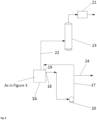
- a jet ejector arrangement 1 comprises a jet ejector 2, comprising an internal nozzle 3 having a base 4 and a tip 5 and, on a common longitudinal axis, an inlet 6 for a motive fluid 10 at the base 4 and an outlet 7 for the accelerated motive fluid at the tip 5; a hollow tube 8 having a base 9 and surrounding the internal nozzle 3, such that the base 9 of the hollow tube 8 surrounds the base 4 of the nozzle 3, and extending downstream the tip 5 such that the chemical components flowing inside the hollow tube 8 reside in the hollow tube 8 for 0.1 to 5 seconds, wherein the flow direction in the hollow tube 8 is defined by the flow direction of the motive fluid 10, for mixing and reacting the motive fluid 10 with an additional fluid feed in a reaction zone 11 in the hollow tube 8, thereby providing a reacted fluid; and an opening 12 in the wall of the hollow tube 8 for entry of the additional fluid feed.
- the arrangement is characterised in that it further comprises a feed line 15 for the additional fluid, external to the jet ejector, of which the feed output end is freely located in the vicinity of the opening 12.
- the motive fluid 10 is delivered into the internal nozzle 3 at a defined pressure.
- the flow section in the nozzle is reduced causing pressure drop and a velocity increase for the motive fluid 10 at the outlet 7 of the nozzle 10.
- the conversion of the static pressure of the motive fluid 10 into velocity generates a corresponding negative pressure at the opening 12 which generates a suction flow.
- the kinetic energy from the motive fluid is transferred to this suction flow. All that is required for this suction flow to be present is that the motive fluid 10 is introduced at the temperature and pressure required to achieve the motive force, typically from 1.5 to 13 bar and from - 600 to 200 °C.
- the suction in the internal nozzle 3 can be used not only to recirculate the additional fluid, such that it is mixed with the motive fluid 10: it is also possible to recirculate, through the opening 12, all of the motive fluid 10 not reacted in the hollow tube 8, the additional fluid not reacted in the hollow tube 8, and also any product formed by the reaction of the motive fluid 10 with the additional fluid. For such recirculation to be possible, all that is required is to introduce the additional fluid in the feed line 15, having its output end in the vicinity of the opening 12.
- a key advantage of the jet arrangement 1 of the disclosure is that, with the product being recirculated, it is possible to retain control on the temperature in the hollow tube 8, while improving the degree of reaction of the motive fluid 10 and the additional fluid: said otherwise, the forced recirculation of the products of the motive fluid 10 and the additional fluid acts as a temperature buffer. Moreover, the temperature in the reaction zone 11 of the hollow tube 8 also remains about constant, that is around the temperature of the expanded fluid at the outlet of the diffusor 13, such that there is no hot spot in the jet ejector arrangement 1, in particular in the reaction zone 11 of the hollow tube 8.
- the jet arrangement of the disclosure is suitable for reacting components and also mixing those components with their products, such that an optimally complete reaction of the reactants is achieved.
- the reactive jet arrangement 1 allows safe reaction of the reactants, such that the temperature inside the jet ejector 2 is within safe limits and remain, throughout the continuous reaction of the two reactants, within those safe limits.
- the outlet 7 for the accelerated motive fluid at the tip 5 of the nozzle 3 extends beyond the opening 12, that is beyond the point of the opening 12 further away from the base 9 of the hollow tube 8. In this manner, any by-pass of the motive fluid 10 through the opening 12 is minimized and entry of any fluid external to the hollow tube 8 inside the hollow tube 8 is maximized. As a result, mixing and reaction in the reaction zone 11 are further improved and proceed faster.
- the arrangement 1 further comprises flow control means in any one of the inlet for the motive fluid 10 and the feed line 15.
- the feed line 15 is located from 1 to 15 cm away from the opening 12.
- the suction at the opening 12 is maximized, such that the recirculation of the motive fluid 10 not reacted in the hollow tube 8, the additional fluid not reacted in the hollow tube 8, and also any product formed by the reaction of the motive fluid 10 with the additional fluid is maximized, thereby maximizing the reaction yield and the temperature buffer effect in the reaction zone 11 of the hollow tube 8.
- the person skilled in the art may optimize the jet ejector arrangement 1 with no difficulty by introducing multiple feed lines 15 for the additional fluid in the vicinity of the opening 12, such that the suction at the opening 12 is optimized.
- the person skilled in the art may also, without any technical difficulty, introduce a shell around the opening 12, such in order to optimize the suction at this opening.
- the jet ejector 2 comprises two openings 12 diametrically opposed in the wall of the hollow tube 8.
- the suction at the hollow tube 8 is increased , thus increasing the recirculation of the motive fluid 10, the additional fluid and their products in the hollow tube 8.
- the reaction of the motive fluid 10 with the additional fluid is improved: it proceeds faster and its yield is increased.
- the openings 12 prevent the reaction zone 11 in the hollow tube 8 from being a closed space, such as is the case in the pipe reactor.
- a system for reacting at least two fluid chemicals with each other comprises:
- the system is characterised in that the at least one jet ejector 2 is entirely located inside the container 16, the opening 12 being in fluid communication with the content of the mixing container 16.
- a jet ejector arrangement 1 When a jet ejector arrangement 1 is arranged entirely inside a container 16, the content of the container is recirculated in the jet ejector arrangement 1, resulting in the benefits mentioned above, namely a safer and more complete reaction of the reactants introduced in the container 16, through the nozzle 2 and the feed line 15 of the jet ejector arrangement 1.
- the jet ejector 2 can also be located outside the container 16.
- the jet ejector 2 can also be partially inside the container 16, such that at least the outlet 7 of the nozzle 3, the opening 12, the reaction zone 11 of the hollow tube 8 and the feed line 15 are inside the container 16. In this manner, it is not necessary to have piping connecting the opening 12 to the container 16.
- jet ejector 2 located outside the container 16, in which case it is necessary to have piping connecting the opening 12 to the container 16.
- the location of the jet ejector 2 outside the container 16 can be beneficial in the case the reaction of the motive fluid 10 and the additional results in the formation of solids clogging the jet ejector 2: when the jet ejector 2 is located outside the container 16, it can be more easily maintained and, in the presence of multiple jet ejector arrangements 1 in the system, it is not necessary to shutdown the system and thereby stop the production processes as only the clogged jet ejectors 2 can be separated from the system and maintained, while production proceeds through other jet ejector arrangements 1 in the system.
- the system comprises four jet ejector arrangements 1 arranged, inside the container 16, symmetrically with respect to each other and tangentially with respect to the wall of the container 16.
- An advantage of the present system is its flexibility: it is possible to perform the reaction of the motive fluid 10 with the additional fluid in a system using a single jet ejector arrangement 1 of the appropriate size and volume. It is also possible to perform the reaction of the motive fluid 10 with the additional fluid using multiple single jet ejector arrangement 1, each of a smaller size and volume than the jet ejector arrangement 1 in the system with a jet ejector arrangement 1. It has been found that using four jet ejector arrangements 1 arranged, inside the container 16, symmetrically with respect to each other and tangentially with respect to the wall of the container 16, provides an optimal recirculation to the opening 12 of the jet ejector 2, and thereby an optimal reaction of the motive fluid 10 with the additional fluid. The presence of multiple jet ejector arrangements 1 has a positive impact on the turndown ratio for the process: it is possible to reduce the production volume by operating only one or some of, and not all the multiple jet ejector arrangements 1.
- the system comprises multiple jet ejector arrangements 1 located in the container 16 and the jet ejectors arrangements 1 are directed such that the flow direction in the jet ejectors 2 is upwards and radially towards the center of the container 16.
- a maximum of the fluid inside the container 16 is recirculated to the openings 12 of the jet ejectors 2.
- a more complete reaction of the motive fluid 10 with the additional fluid is achieved.
- a system with an arrangement of jet ejector arrangements 1 in series can provide optimal recirculation of a maximum volume of the fluid in the container 16.
- the container 16 has a volume ranging from 0.5 to20 m 3 .
- the reaction of the motive fluid 10 with the additional fluid is improved. Consequently, the size and volume of the jet ejector 2 can be minimized.
- less volume of the container 16 has to be accounted for recycling to the opening of the jet ejectors 2 when they are located inside the container 16.
- a large hold-up volume in the container 16 is not necessary to ensure temperature control in the mixing zone 11 of the hollow tube 8. This means that the volume of the container 16 can be minimized when a jet ejector arrangement 1 according to the disclosure is used. Consequently, the system of the disclosure offers the advantage of a reduced footprint.
- the system comprises:
- Dead zones in the container 16 are typically minimized by placing an active mixing device, such as an agitator, and by having a continuous recirculation flow inside the container 16, through the means 20.
- the means 20 are a pump, downstream the tank reactor, in order to supply the content of the container 16 according to the demand.
- the recirculation line 17 usually to the top of the container 16 or through a so-called dip pipe.
- the recirculation line 17 not only preserved the means 20, it also ensures mixing in the container 16.
- an additional jet ejector 2 is used as the active device minimizing, and even eliminating the dead zones inside the container 16. As long as a motive fluid 10 is forced through the nozzle 3 of the additional jet ejector 2, a suction at the opening of the additional jet ejector 2 results in the mixing of the fluid in the container 16, thereby minimizing and even eliminating the dead zones inside the container 16.
- the outlet 19 of the recirculation line 17 is in fluid communication with the inlet of the nozzle of a jet ejector 2, the flow direction in this jet ejector 2 being upwards and tangential with respect to the wall of the container 16.
- the motive fluid 10 in the nozzle 3 of the additional jet ejector 2 can be the fluid from the outlet 19 of the recirculation line 17.
- the mixing effect of the recirculation line 17, combined with the suction effect at the opening 12 of the nozzle 3 of the additional jet ejector 2 provides an optimal mixing and reaction of the fluids in the container 16.
- the motive flow 10 from the outlet 19 of the recirculation 17, in the additional jet ejector 2 can be directed to the bottom of the container 16, the additional jet ejector 2 being located at the center of the container 16.
- system further comprises temperature adjustment means in the recirculation line 17.
- the temperature of the fluid recirculated to the container is controlled, such that, in turn, the temperature of the liquid inside the container 16, and thereby inside the jet ejector 2 to which the fluids inside the container 16 are recirculated through the opening 12 of the jet ejector 2, is also controlled. This offers additional safety and reaction control.
- the container 16 comprising an outlet 18 for its liquid content in the form of an overflow.
- the outlet 18 of the container can correspond to the inlet 18 of the recirculation line 17. It is preferred that the fluids in the container 16, once they have been sufficiently reacted through the jet ejector 2, that is after the motive fluid 10 and the additional fluid have been recirculated a sufficient number of times in the jet ejector 2 through the opening 12 of the ejector 2 such that the fluids in the container 16 contain the desired percentage of the liquid product formed by the reaction of the motive fluid 10 and the additional fluid, leave the container 16 in the form of an overflow. In this manner, no additional power, such as the power required to power a pump, is required to extract the fluids from the container 16.
- system further comprises means for recovering heat 21.
- reaction of the motive fluid 10 with the additional fluid is an exothermic reaction and produces heat
- the system of the disclosure allows for the integration of such means for recovering heat.
- system further comprises means for separating out steam from the container and means for cleaning the separated steam 23.
- the system of the disclosure can further comprise means for separating out steam (not shown), such as a steam separator or a demister which can be located inside the container (16).
- the system can also comprise means for cleaning the separated steam 23, such as a washing column.
- the amount of aerosols and droplets of the product leaving the container 16 with the steam depends on the production rate.
- the system of the disclosure offers better steam separation from the fluids in the container 16, that is a better separation of gases from liquids, than a system comprising a pipe reactor.
- the fluids in the container 16 act as an internal buffer, such that the steam leaving the container 16 requires less separation, in the means for separating out steam 22 such as a steam separator, from droplets of the fluids in the container 16. Also, the steam leaving the container 16 requires less cleaning, in the means for cleaning 23 such as a washing column, from vapours of the fluids in the container 16.
- a method for reacting two fluids in a system according to the system of the disclosure comprises the steps of:
- the motive fluid 10 is delivered into the internal nozzle 3 at a defined pressure.
- the flow section in the nozzle is reduced causing pressure drop and a velocity increase for the motive fluid 10 at the outlet 7 of the nozzle 10.
- the conversion of the static pressure of the motive fluid 10 into velocity generates a corresponding negative pressure at the opening 12 which generates a suction flow.
- the kinetic energy from the motive fluid is transferred to this suction flow. All that is required for this suction flow to be present is that the motive fluid 10 is introduced at the pressure required to achieve the motive force, typically from 3 to 6 bar.
- the suction in the internal nozzle 3 can be used not only to recirculate the additional fluid, such that it is mixed with the motive fluid 10: it is also possible to recirculate, through the opening 12, all of the motive fluid 10 not reacted in the hollow tube 8, the additional fluid not reacted in the hollow tube 8, and also any product formed by the reaction of the motive fluid 10 with the additional fluid. For such recirculation to be possible, all that is required is to introduce the additional fluid in the feed line 15, having its output end in the vicinity of the opening 12.
- a key advantage of the jet arrangement 1 of the disclosure is that, with the product being recirculated, it is possible to retain control on the temperature and pressure in the hollow tube 8, while improving the degree of reaction of the motive fluid 10 and the additional fluid: said otherwise, the forced recirculation of the products of the motive fluid 10 and the additional fluid acts as a temperature buffer. Moreover, the temperature in the reaction zone 11 of the hollow tube 8 also remains about constant, that is about the temperature of the expanded fluid at the outlet of the diffusor 13, such that there is no hot spot in the jet ejector arrangement 1, in particular in the reaction zone 11 of the hollow tube 8.
- the jet arrangement of the disclosure is suitable for reacting components and also mixing those components with their products, such that an optimally complete reaction of the reactants is achieved.
- the reactive jet arrangement 1 allows safe reaction of the reactants, such that the temperature and the pressure inside the jet ejector 2 are within safe limits and remain, throughout the continuous reaction of the reactants, within those safe limits.
- the fluid fed in step a) is a gas. It is particularly advantageous to use a gas as the motive fluid 10, as the velocity of the gas at the outlet 7 of the nozzle 3 is further expanded compared to when the motive fluid 10. Consequently, the velocity of the motive fluid 10 at the outlet 7 of the nozzle 3 is further increased compared to when the motive fluid 10. As a result, the suction flow to the opening 12 of the jet ejector 2 is increased. Thereby, the mixing and the reacting of the motive fluid 10 and of the additional fluid are increased and improved.
- the method further comprises the step of: c) recirculating the content of the container 16 back to the container 16.
- Dead zones in the container 16 are typically minimized by placing an active mixing device, such as an agitator, and by having a continuous recirculation flow inside the container 16, through the means 20.
- the means 20 are a pump, downstream the tank reactor, in order to supply the content of the container 16 according to the demand.
- the recirculation line 17 usually to the top of the container 16 or through a so-called dip pipe.
- the recirculation line 17 not only preserved the means 20, it also ensures mixing in the container 16.
- an additional jet ejector 2 is used as the active device minimizing, and even eliminating the dead zones inside the container 16. As long as a motive fluid 10 is forced through the nozzle 3 of the additional jet ejector 2, a suction at the opening of the additional jet ejector 2 results in the mixing of the fluid in the container 16, thereby minimizing and even eliminating the dead zones inside the container 16.
- the method is performed in a system according to a system of the disclosure comprising at least two jet ejectors 2 and, in step c), the content of the mixing container 16 is recirculated to the inlet of the nozzle 3 of the at least second jet ejector 2.
- the motive fluid 10 in the nozzle 3 of the additional jet ejector 2 can be the fluid from the outlet 19 of the recirculation line 17.
- the mixing effect of the recirculation line 17, combined with the suction effect at the opening 12 of the nozzle 3 of the additional jet ejector 2, provides an optimal mixing and reaction of the fluids in the container 16.
- the method further comprises the step of: d) operating flow control means in the inlet (6) for the motive fluid (10) and in the feed line (15) of the at least one jet ejector arrangement (1), such as to control the ratio of the flow of the motive fluid (10) over the flow in the feed line (15).
- the nozzle 3 of the at least one jet ejector arrangement 1 is operated at atmospheric pressure.
- the operating pressure is a measure, added to that of the system of the disclosure itself ensuring stability of the pressure and temperature in the hollow tube 8 of the at least one ejector 2, for safely operating the system of the disclosure.
- the method further comprises the step of: e) adjusting the temperature of the content being recirculated during step c).
- the temperature of the fluid recirculated to the container is controlled, such that, in turn, the temperature of the liquid inside the container 16, and thereby inside the jet ejector 2 to which the fluids inside the container 16 are recirculated through the opening 12 of the jet ejector 2, is also controlled. This offers additional safety and reaction control.
- the fluid fed as the motive fluid 10 in step a) is gaseous ammonia and the fluid fed in step b) is nitric acid, such that the method produces ammonium nitrate.
- ammonium nitrate involves the reaction as ammonia gas.
- ammonia gas is the motive fluid 10
- the suction flow to the opening 12 of the jet ejector 2 is increased.
- the mixing and the reacting of ammonia gas and nitric acid are increased and improved.
- the pH is controlled such that the reaction between ammonia and nitric acid is optimized.
- the method further comprises the step of: f) recovering the heat generated by the combination of steps a) and b).
- reaction of the motive fluid 10 with the additional fluid is an exothermic reaction and produces heat
- the system of the disclosure allows for the integration of such means for recovering heat. For example, the heat generated in the production of ammonium nitrate can be recovered.
- the system of the disclosure can further comprise means for separating out steam 22, such as a steam separator.
- the system can also comprise means for cleaning the separated steam 23, such as a washing column.
- the amount of aerosols and droplets of the product leaving the container 16 with the steam depends on the production rate.
- the system of the disclosure offers better steam separation from the fluids in the container 16, that is a better separation of gases from liquids, than a system comprising a pipe reactor.
- the fluids in the container 16 act as an internal buffer, such that the steam leaving the container 16 requires less separation, in the means for separating out steam 22 such as a steam separator, from droplets of the fluids in the container 16. Also, the steam leaving the container 16 requires less cleaning, in the means for cleaning 23 such as a washing column, from vapours of the fluids in the container 16.
- the motive fluid 10 in step a) is ammonia gas, at a temperature ranging from 50 to 200 °C and a pressure ranging from 1.5 to 13 bar, and, in step b), from 53 weight% to 63 weight% nitric acid is fed, at a temperature ranging from 20 to 100 °C and a pressure ranging from 1.5 to 3 bar.
- a 92 to 99 weight% ammonium nitrate solution can be produced and requires no subsequent evaporation step.
- the temperature inside the system is kept at safe levels, that is below or at about 180 °C, at all times during the reaction. Furthermore, the power consumption associated to pressurizing and heating the reactants is minimized. Also, not only is the power consumption for practicing the process reduced, heat is also produced and can be, as described above, recovered.
- the method is performed in a batch manner or continuously.
- the use of the system for the disclosure for reacting an acid with a base, or as a bleacher or a stripper, or as a fertilizer slurry container, or as reactor in which emergency water can be introduced, is disclosed.
- the reaction of an acid with a base is known as a neutralization reaction and is known to produce heat. It is essential that that the acid and the base are sufficiently brought into contact with each other to be fully reacted. It is further important to retain control on the temperature of the neutralization reaction and to have the appropriate elements in the system for recovering heat.
- the system of the disclosure is especially suitable for reacting and acid with a base.
- the acid is nitric acid, sulfuric acid, phosphoric acid, hydrofluoric acid, hexafluorosilicic acid, metasilicilic acid or a mixture thereof.
- the base is ammonia, more in particular, ammonia gas, sodium hydroxide, potassium hydroxide, calcium hydroxide, magnesium carbonate, sodium carbonate and sodium bicarbonate.
- a bleaching or a stripping system involves both a bleaching or a gaseous stripping medium respectively and a liquid medium to be bleached or stripped respectively.
- the gaseous bleaching or stripping medium must be effectively mixed with the liquid medium to be bleached or stripped. Therefore, the gaseous bleaching or stripping medium can be introduced in the system of the disclosure as the motive fluid 10 and the liquid medium to be bleached can be introduced in the system of the disclosure as the additional fluid through the feed line 15.
- the production of fertilizer slurries also involves the mixing and reaction of salt solutions such as ammonium salts suspensions or solutions and urea suspensions or solutions.
- salt solutions such as ammonium salts suspensions or solutions and urea suspensions or solutions.
- one of the salt solution to be mixed and reacted is ammonium nitrate, ammonium sulphate, mono ammonium phosphate diammonium phosphate or a mixture thereof.
- the ammonium salt solution can be produced in a first stage from the reaction of an acid with a base, as described above, and subsequently further reacted with another component, such as urea in a urea solution.
- Temperature, pressure and pH control in the production of such fertilizer slurries is critical. Therefore, the system of the disclosure is especially suitable for use in the production of fertilizer slurries.
- the system of the disclosure is particularly suited.
- water is introduced in a medium for the purpose of cooling and maintaining temperature, if introduced at the top of the medium requiring cooling the mixing may not be sufficient to achieve the target safety temperature range.
- Deep pipes have tried to remediate to this issue by enabling water to be flown to the bottom of a container, the temperature inside which requires to be lowered.
- this has been observed that water tends to settle at the bottom of the container and does not properly mix with the content in the upper part of the container.
- the system of the disclosure having the potential to both recirculate the entire content of the container 16 to the opening 12 of the jet ejector 2, and to mix the motive fluid 10 and the additional fluid inside the jet ejector 2, the efficient mixing of water of an entire defined volume requiring cooling, can be achieved with the system of the disclosure. Therefore, the system of the disclosure provides additional safety potential.
- a method for designing a jet ejector arrangement 1 comprises the steps of:
- the suction in the internal nozzle 3 can be used not only to recirculate the additional fluid, such that it is mixed with the motive fluid 10: it is also possible to recirculate, through the opening 12, all of the motive fluid 10 not reacted in the hollow tube 8, the additional fluid not reacted in the hollow tube 8, and also any product formed by the reaction of the motive fluid 10 with the additional fluid.
- all that is required is to introduce the additional fluid in the feed line 15, having its output end in the vicinity of the opening 12.
- the inventors have further realized that it is possible to determine the optimal dimensions and location in the hollow tube (8) and with respect to the internal nozzle (3) through computational fluid modeling (CFD): by simulating through CFD the design of the jet ejector arrangement (1) and the mixing and the reaction of the motive fluid (10) with the additional fluid in the jet ejector arrangement (1), it is possible to determine the optimal dimensions and location in the hollow tube (8) and with respect to the internal nozzle (3), in order for the mixing and the reaction of the motive fluid (10) with the additional fluid in the jet ejector arrangement (1) to be optimal.
- CFD computational fluid modeling
- a system comprising a jet ejector arrangement (1), comprising a jet ejector (2), comprising an internal nozzle (3) having a base (4) and a tip (5) and, on a common longitudinal axis, an inlet (6) for a motive fluid (10) at the base (4) and an outlet (7) for the accelerated motive fluid at the tip (5); a hollow tube (8) having a base (9) and surrounding the internal nozzle (3), such that the base (9) of the hollow tube (8) surrounded the base (4) of the nozzle (3), and extended downstream the tip (5) such that the components inside the hollow tube (8) resided in the hollow tube (8) for 0.1 to 5 seconds, wherein the flow direction in the hollow tube (8) was defined by the flow direction of the motive fluid (10), for mixing and reacting the motive fluid (10) with an additional fluid feed in a reaction zone (11) in the hollow tube (8), thereby providing a reacted fluid; an opening (12) in the wall of the hollow tube (8) for
- the outlet (7) of the tip (5) of the nozzle (3) was located downstream to the opening (12).
- Ammonia gas was fed as the motive fluid (10) at a temperature ranging from 50 to 200 °C and a pressure ranging from 1.5 to 13 bar, and from 53 weight% to 63 weight% nitric acid was fed as the additional fluid, at a temperature ranging from 20 to 100 °C and a pressure ranging from 1.5 to 3 bar.
- the temperature in the hollow tube (8) was controlled to about 180 °C during the reaction of ammonia and nitric acid. A 92 weight% solution of ammonium nitrate was obtained (24). Furthermore, the steam (22) from the container (16) naturally disengaged from the container (16).
Landscapes
- Engineering & Computer Science (AREA)
- Physics & Mathematics (AREA)
- Fluid Mechanics (AREA)
- Mechanical Engineering (AREA)
- General Engineering & Computer Science (AREA)
- Physical Or Chemical Processes And Apparatus (AREA)
- Accessories For Mixers (AREA)
Priority Applications (6)
| Application Number | Priority Date | Filing Date | Title |
|---|---|---|---|
| EP21214101.4A EP4194704A1 (fr) | 2021-12-13 | 2021-12-13 | Agencement d'éjecteur de jet, système et utilisation associés et son procédé de fonctionnement |
| AU2022413339A AU2022413339A1 (en) | 2021-12-13 | 2022-12-13 | Jet ejector arrangement, system and use thereof and method for operating the same |
| PCT/EP2022/085508 WO2023110808A1 (fr) | 2021-12-13 | 2022-12-13 | Agencement d'éjecteur à jet, système et son utilisation et procédé pour l'exploiter |
| US18/712,803 US20250276337A1 (en) | 2021-12-13 | 2022-12-13 | Jet ejector arrangement, system and use thereof and method for operating the same |
| CN202280061215.7A CN117916472A (zh) | 2021-12-13 | 2022-12-13 | 射流喷射器布置、系统和其用途以及其操作方法 |
| EP22835728.1A EP4448973B1 (fr) | 2021-12-13 | 2022-12-13 | Agencement d'éjecteur de jet, système et utilisation associés et son procédé de fonctionnement |
Applications Claiming Priority (1)
| Application Number | Priority Date | Filing Date | Title |
|---|---|---|---|
| EP21214101.4A EP4194704A1 (fr) | 2021-12-13 | 2021-12-13 | Agencement d'éjecteur de jet, système et utilisation associés et son procédé de fonctionnement |
Publications (1)
| Publication Number | Publication Date |
|---|---|
| EP4194704A1 true EP4194704A1 (fr) | 2023-06-14 |
Family
ID=78844779
Family Applications (2)
| Application Number | Title | Priority Date | Filing Date |
|---|---|---|---|
| EP21214101.4A Withdrawn EP4194704A1 (fr) | 2021-12-13 | 2021-12-13 | Agencement d'éjecteur de jet, système et utilisation associés et son procédé de fonctionnement |
| EP22835728.1A Active EP4448973B1 (fr) | 2021-12-13 | 2022-12-13 | Agencement d'éjecteur de jet, système et utilisation associés et son procédé de fonctionnement |
Family Applications After (1)
| Application Number | Title | Priority Date | Filing Date |
|---|---|---|---|
| EP22835728.1A Active EP4448973B1 (fr) | 2021-12-13 | 2022-12-13 | Agencement d'éjecteur de jet, système et utilisation associés et son procédé de fonctionnement |
Country Status (5)
| Country | Link |
|---|---|
| US (1) | US20250276337A1 (fr) |
| EP (2) | EP4194704A1 (fr) |
| CN (1) | CN117916472A (fr) |
| AU (1) | AU2022413339A1 (fr) |
| WO (1) | WO2023110808A1 (fr) |
Citations (6)
| Publication number | Priority date | Publication date | Assignee | Title |
|---|---|---|---|---|
| US3938738A (en) * | 1974-03-06 | 1976-02-17 | Basf Aktiengesellschaft | Process for drawing in and compressing gases and mixing the same with liquid material |
| GB2026611A (en) | 1977-11-01 | 1980-02-06 | Koerting Ag | Ejector for simultaneously pumping from separate gas and liquid inlets |
| EP0272974B1 (fr) | 1986-12-18 | 1993-09-15 | Grande Paroisse S.A. | Procédé de neutralisation d'acides par l'ammoniac |
| US20050119515A1 (en) * | 2002-03-13 | 2005-06-02 | Basf Aktiengesellschaft | Partial dehydrogenation method using continuous heterogeneous catalysis |
| US20080073444A1 (en) * | 2006-09-21 | 2008-03-27 | Basf Aktiengesellschaft | Process for mixing a liquid or mixture of a liquid and a fine solid present in an essentially self-containing vessel |
| US20140064017A1 (en) * | 2006-09-21 | 2014-03-06 | Basf Aktiengesellschaft | Process for mixing a liquid or mixture of a liquid and a fine solid present in an essentially self-containing vessel |
-
2021
- 2021-12-13 EP EP21214101.4A patent/EP4194704A1/fr not_active Withdrawn
-
2022
- 2022-12-13 AU AU2022413339A patent/AU2022413339A1/en active Pending
- 2022-12-13 WO PCT/EP2022/085508 patent/WO2023110808A1/fr not_active Ceased
- 2022-12-13 US US18/712,803 patent/US20250276337A1/en active Pending
- 2022-12-13 CN CN202280061215.7A patent/CN117916472A/zh active Pending
- 2022-12-13 EP EP22835728.1A patent/EP4448973B1/fr active Active
Patent Citations (6)
| Publication number | Priority date | Publication date | Assignee | Title |
|---|---|---|---|---|
| US3938738A (en) * | 1974-03-06 | 1976-02-17 | Basf Aktiengesellschaft | Process for drawing in and compressing gases and mixing the same with liquid material |
| GB2026611A (en) | 1977-11-01 | 1980-02-06 | Koerting Ag | Ejector for simultaneously pumping from separate gas and liquid inlets |
| EP0272974B1 (fr) | 1986-12-18 | 1993-09-15 | Grande Paroisse S.A. | Procédé de neutralisation d'acides par l'ammoniac |
| US20050119515A1 (en) * | 2002-03-13 | 2005-06-02 | Basf Aktiengesellschaft | Partial dehydrogenation method using continuous heterogeneous catalysis |
| US20080073444A1 (en) * | 2006-09-21 | 2008-03-27 | Basf Aktiengesellschaft | Process for mixing a liquid or mixture of a liquid and a fine solid present in an essentially self-containing vessel |
| US20140064017A1 (en) * | 2006-09-21 | 2014-03-06 | Basf Aktiengesellschaft | Process for mixing a liquid or mixture of a liquid and a fine solid present in an essentially self-containing vessel |
Also Published As
| Publication number | Publication date |
|---|---|
| EP4448973A1 (fr) | 2024-10-23 |
| EP4448973B1 (fr) | 2025-08-27 |
| US20250276337A1 (en) | 2025-09-04 |
| EP4448973C0 (fr) | 2025-08-27 |
| CN117916472A (zh) | 2024-04-19 |
| AU2022413339A1 (en) | 2024-03-28 |
| WO2023110808A1 (fr) | 2023-06-22 |
Similar Documents
| Publication | Publication Date | Title |
|---|---|---|
| CN101918357B (zh) | 尿素制备方法及设备 | |
| US10501407B2 (en) | Urea manufacturing method and urea manufacturing apparatus | |
| KR20010110300A (ko) | 기-액, 액-액 또는 기-액-고 화학 반응 수행용 반응기 | |
| CN101304944A (zh) | 二氧化氯的制备方法 | |
| CN113372192A (zh) | 一种低碳醇钠的合成方法 | |
| CN109161401B (zh) | 一种氯化石蜡副产盐酸的生产系统 | |
| JPS602242B2 (ja) | 二酸化塩素の製造法 | |
| CN112723996A (zh) | 一种环氧乙烷法制备乙二醇的强化微界面反应系统及方法 | |
| EP4448973B1 (fr) | Agencement d'éjecteur de jet, système et utilisation associés et son procédé de fonctionnement | |
| CN112456450A (zh) | 一种含有机物废硫酸资源化利用的系统和方法 | |
| KR870001236B1 (ko) | 우레아 제조방법 | |
| JPS6117821B2 (fr) | ||
| US20050281731A1 (en) | Concurrent low-pressure manufacture of hypochlorite | |
| EP4347485B1 (fr) | Système d'évacuation de gaz nox à partir d'un réservoir de stockage d'acide nitrique | |
| CN206715898U (zh) | 环流喷雾连续气液反应器 | |
| CN115337893B (zh) | 高速喷流撞击管式反应器制备碳酸乙烯酯的装置及方法 | |
| CN111892479B (zh) | 一种提高合成氯甲烷中甲醇一次转化率的方法及装置 | |
| JP2003236594A (ja) | 汚泥の処理装置 | |
| CN109293512A (zh) | 丙烯酸酯类产品生产装置 | |
| CN114618418B (zh) | 一种用于Saucy-Marbet反应的装置和烯酮的制备方法 | |
| CN111138267A (zh) | 一种利用低碳醛通过空气氧化制备低碳酸的方法 | |
| WO2005075347A2 (fr) | Fabrication par tour a garnissage concurrent d'hypochlorite | |
| CN215506702U (zh) | 一种用液氯生产次氯酸钠的装置 | |
| JPH02279508A (ja) | 高濃度NO↓xガスの製造方法およびその装置 | |
| CN101357752A (zh) | 氯酸盐法制备二氧化氯 |
Legal Events
| Date | Code | Title | Description |
|---|---|---|---|
| PUAI | Public reference made under article 153(3) epc to a published international application that has entered the european phase |
Free format text: ORIGINAL CODE: 0009012 |
|
| STAA | Information on the status of an ep patent application or granted ep patent |
Free format text: STATUS: THE APPLICATION HAS BEEN PUBLISHED |
|
| AK | Designated contracting states |
Kind code of ref document: A1 Designated state(s): AL AT BE BG CH CY CZ DE DK EE ES FI FR GB GR HR HU IE IS IT LI LT LU LV MC MK MT NL NO PL PT RO RS SE SI SK SM TR |
|
| STAA | Information on the status of an ep patent application or granted ep patent |
Free format text: STATUS: THE APPLICATION IS DEEMED TO BE WITHDRAWN |
|
| 18D | Application deemed to be withdrawn |
Effective date: 20231215 |