EP4197074B1 - Dichtung für ein elektrisches kabel - Google Patents
Dichtung für ein elektrisches kabel Download PDFInfo
- Publication number
- EP4197074B1 EP4197074B1 EP21743104.8A EP21743104A EP4197074B1 EP 4197074 B1 EP4197074 B1 EP 4197074B1 EP 21743104 A EP21743104 A EP 21743104A EP 4197074 B1 EP4197074 B1 EP 4197074B1
- Authority
- EP
- European Patent Office
- Prior art keywords
- sealing
- grommet
- sealing lips
- face
- cable
- Prior art date
- Legal status (The legal status is an assumption and is not a legal conclusion. Google has not performed a legal analysis and makes no representation as to the accuracy of the status listed.)
- Active
Links
Images



Classifications
-
- H—ELECTRICITY
- H01—ELECTRIC ELEMENTS
- H01B—CABLES; CONDUCTORS; INSULATORS; SELECTION OF MATERIALS FOR THEIR CONDUCTIVE, INSULATING OR DIELECTRIC PROPERTIES
- H01B17/00—Insulators or insulating bodies characterised by their form
- H01B17/56—Insulating bodies
- H01B17/58—Tubes, sleeves, beads, or bobbins through which the conductor passes
- H01B17/583—Grommets; Bushings
-
- H—ELECTRICITY
- H02—GENERATION; CONVERSION OR DISTRIBUTION OF ELECTRIC POWER
- H02G—INSTALLATION OF ELECTRIC CABLES OR LINES, OR OF COMBINED OPTICAL AND ELECTRIC CABLES OR LINES
- H02G3/00—Installations of electric cables or lines or protective tubing therefor in or on buildings, equivalent structures or vehicles
- H02G3/22—Installations of cables or lines through walls, floors or ceilings, e.g. into buildings
-
- B—PERFORMING OPERATIONS; TRANSPORTING
- B60—VEHICLES IN GENERAL
- B60R—VEHICLES, VEHICLE FITTINGS, OR VEHICLE PARTS, NOT OTHERWISE PROVIDED FOR
- B60R16/00—Electric or fluid circuits specially adapted for vehicles and not otherwise provided for; Arrangement of elements of electric or fluid circuits specially adapted for vehicles and not otherwise provided for
- B60R16/02—Electric or fluid circuits specially adapted for vehicles and not otherwise provided for; Arrangement of elements of electric or fluid circuits specially adapted for vehicles and not otherwise provided for electric constitutive elements
- B60R16/0207—Wire harnesses
- B60R16/0215—Protecting, fastening and routing means therefor
- B60R16/0222—Grommets
-
- H—ELECTRICITY
- H02—GENERATION; CONVERSION OR DISTRIBUTION OF ELECTRIC POWER
- H02G—INSTALLATION OF ELECTRIC CABLES OR LINES, OR OF COMBINED OPTICAL AND ELECTRIC CABLES OR LINES
- H02G15/00—Cable fittings
- H02G15/013—Sealing means for cable inlets
Definitions
- the subject matter relates to a seal for an electrical cable and a housing with such a seal.
- the sealing of electrical cables is extremely relevant to the durability of the electrical installation.
- high demands are placed on the sealing of cable entries in housings. This is due, on the one hand, to the dynamic load situation of the cable entry into the housing and, on the other hand, to the high load caused by corrosive substances, such as salty water. It must be prevented that moisture along the cable gets through the seal into a housing and attacks the electrical connection(s) located there.
- the publication EP 3 279 537 A1 shows a sealing element that compensates for a deviation in the orientation or arrangement of elements, for example a treatment device for electrolytic or wet chemical treatment.
- the publication EP 0 823 763 A1 relates to a grommet for sealing an opening in a plate through which at least one cable passes, and in particular to a grommet which in used in the automotive industry to seal an opening in a panel that separates the engine compartment from the passenger compartment against water, heat and dirt and through which at least one cable or wiring passes.
- the publication US 5,155,303 A relates to a cable closure that includes at least one grommet with improved sealing ability.
- the publication US 6,438,828 B1 relates to an arrangement and method for sealing a wire harness passing through a grommet installed in a through hole in a panel of a motor vehicle.
- the publication JP H 08 107620 A relates to a grommet inserted into a hole in a body panel of an automobile or the like to hold electrical wires.
- the publication CN 210 830 473 U belongs to the technical field of engine shaft seals, especially an engine shaft seal.
- the object of the object was to provide a seal which enables a secure seal against the ingress of longitudinal water in a wide variety of cable geometries.
- Automotive electrical systems are in particular the electrical systems of motor vehicles, especially cars or trucks, but also two-wheelers and other motor vehicles.
- the electrical cable usually has a metallic cable core, which is made of solid material or strands and an insulator surrounding this core.
- An electrical cable is usually stripped from the front in order to make contact with other cables or electrical components.
- the then bare metal of the cable core is connected to the other component, in particular in a form-fitting and/or cohesive manner, for example by screwing, soldering, welding or the like.
- the transition between the two metallic components must be protected from corrosion.
- Such a transition is often within a housing that is inherently waterproof.
- inserting the cable into the housing presents a challenge in terms of waterproofing.
- An electrical cable with its insulator is usually inserted into a housing through a grommet.
- the grommet has a passage through which the cable extends.
- the through-channel of a grommet extends from a first end face to a second end face of the grommet. This through-channel is circumscribed by an inner lateral surface of the grommet. This inner surface usually serves to seal the cable.
- a grommet In order to achieve an improved sealing effect compared to a shrink tube, a grommet generally has at least two inwardly facing sealing lips which are spaced apart from one another in the longitudinal direction and are arranged on the inner lateral surface of the grommet.
- the sealing lips are preferably completely circumferential and lie closely against the cable.
- the sealing lips enable the inner clear width of the grommet to be adapted to different cable cross sections.
- the sealing lips have approximately the same material thickness as the rest of the lateral surface and are elastically deformable.
- the sealing lips point radially inwards.
- the sealing lips can do better elastically deform radially outwards than the outer surface of the grommet itself. As a result, the sealing lips lie closer to the cable than just an ordinary grommet. This applies in particular to irregularities on the outer circumference of the cable, where the sealing lips still provide a sealing effect.
- the grommet in question has at least two sealing areas arranged next to one another in the longitudinal direction and spaced apart from one another by a circumferential separating area. These two sealing areas are arranged on the respective end faces of the grommet, with a first sealing area of the sealing areas facing the first end face and a second sealing area of the sealing areas facing the second end face.
- the separation area which has a smaller wall thickness of the lateral surface of the grommet than the lateral surface of the grommet in the sealing areas, ensures that the sealing areas can move relative to one another under dynamic loads without any movement in the first sealing area causing a significant impairment of the Sealing effect leads to the second sealing area and/or vice versa.
- the wall thickness refers to the grommet, in particular the wall thickness of the lateral surface of the grommet, in particular the distance between the inner and outer lateral surface of the grommet.
- the smaller wall thickness means that the grommet has increased elasticity in the separation area. This increased elasticity enables the areas to be movable relative to one another both in the longitudinal direction and radially to the longitudinal direction.
- the separating region is formed by a circumferential, radially inwardly pointing groove.
- This groove is attached to the outer surface of the grommet and delimits the first from the second sealing area.
- the groove reduces the wall thickness of the grommet in the area of the groove base compared to at least parts of the rest of the grommet, so that the grommet is more flexible in the area of the groove than in the area away from the groove. It is suggested that the groove is a groove.
- the groove is formed from the first sealing region by a radially inwardly extending first flank to the second sealing region by a radially outwardly extending flank.
- the flanks form the groove walls.
- the outer lateral surface initially extends essentially parallel to the longitudinal axis of the grommet in the first sealing area.
- the outer lateral surface then runs at least partially radially inwards along the first flank.
- the outer lateral surface runs along the second flank radially outwards towards the second sealing region, in which the outermost lateral surface extends essentially parallel to the longitudinal axis of the grommet.
- the first flank is inclined at a greater angle to the longitudinal axis than the second flank.
- sealing lips are arranged in each of the sealing areas.
- sealing lips pointing radially inwards are provided on the inner surface of the sleeve.
- Each of the sealing areas has at least one, preferably at least two, such sealing lips.
- the taper in the separating area allows the sealing areas to swing against each other. If at least one sealing lip is arranged in each of the sealing areas, improved sealing against longitudinal water ingress can be achieved.
- the wall thickness of the second sealing area tapers towards the second end face. This then smaller wall thickness leads to a higher elastic flexibility and thus a better fit of the inner lateral surface of the second sealing area to the outer circumference of the cable arranged in the grommet.
- a radially inwardly extending longitudinal axis of the sealing lips is inclined relative to a transverse plane running perpendicular to the longitudinal axis.
- the sealing lips have a radial, inwardly extending longitudinal extent.
- the axis of this longitudinal extension is inclined relative to a radius that runs perpendicular to the longitudinal axis.
- the inclination is in particular such that the sealing lips are inclined in the direction of the second end face. This inclination of the sealing lips relative to the radius enables the sealing lips to rest on the inserted cable with a larger contact surface.
- a particularly high level of sealing against longitudinal water ingress for both flat cables and round cables is achieved according to the invention in that two sealing lips arranged next to one another in the longitudinal direction have cross-sectional profiles that differ from one another.
- two sealing lips arranged next to one another can have cross-sectional profiles that differ from one another.
- the different cross-sectional profiles mean that in a wide variety of, often dynamic, load situations, at least one of the sealing lips always lies closely against the cable and thus ensures a tight seal.
- the cross-sectional profile of the sealing lip can be relevant for its tightness. If two sealing lips arranged next to each other with different cross-sectional profiles are formed, this results in an optimized seal.
- the sealing lips are inclined relative to an axis running perpendicular to the longitudinal axis.
- two sealing lips arranged next to one another in the longitudinal direction of the grommet are inclined differently from one another to the transverse plane.
- the angle of inclination is alternating, so that one of at least two angles of inclination is intermittently realized on the sealing lips.
- the different cross-sectional profiles are such that at least one of the sealing lips has a tapering cross-sectional profile and that at least one of the sealing lips has an arcuate cross-sectional profile.
- Arcuate can also be understood as spherical and pointed can also be understood as arrow-shaped.
- each of the sealing lips has side walls that extend towards an end face.
- the side walls extend along the longitudinal extent of the sealing lip and run essentially parallel to one another.
- the length of the side walls is different from one another, with the side wall facing the first end face preferably being longer than the side wall facing the second end face.
- This different design of the side walls results in an inclination of the sealing lips towards the second end face.
- the sealing lips preferably lie on the cable with their side wall facing the first end face and seal this.
- each of the sealing lips creates a clear opening in the through-channel.
- the sealing lips form the passage channel with a clear opening in the grommet.
- the clear opening is the area that is free in the passage channel for the cable.
- the cable goes into the through channel inserted.
- the clear opening of the through channel in the uninstalled state of the grommet differs from the cross-sectional profile of the cable to be accommodated. If the cable is inserted into the clear opening, the grommet deforms elastically and the sealing lips are pressed against the outer circumference of the cable.
- the circumference of the clear opening of the through channel is preferably smaller than the outer circumference of the cable to be accommodated.
- the clear opening is preferably spanned by two opposing long sides and two opposing transverse sides of the sealing lip. This means that the clear opening is preferably not round or oval, but essentially rectangular, with radii being able to be formed in the respective corners in order to enable a particularly good adaptation of the sealing lips to the cable to be received.
- the clear opening is essentially rectangular, with radii can be formed at the corners.
- a transition between a long side and a transverse side has an inner radius.
- Such an inner radius should generally be smaller than an outer radius of the counterpart/cable to be sealed.
- At least one of the longitudinal sides is curved radially inwards and/or that at least one of the transverse sides is curved radially inwards.
- At least one longitudinal and/or at least one transverse side can be curved radially inwards.
- a sealing lip with inwardly curved sides can alternate with a sealing lip with sides running parallel to one another.
- a bellows can be arranged on the grommet between the first sealing area and the first end face in order to enable movement of the grommet relative to the housing having the grommet.
- a flange extending radially outwards is arranged on the first end face.
- the flange can be arranged on the housing and pressed into the housing wall.
- the flange can be used to seal a receptacle/opening in the housing relative to the grommet.
- FIG. 1 Another aspect is a housing with a seal described above.
- This housing has a receptacle/opening to accommodate a cable.
- a functional grommet can be arranged on this receptacle, which can be arranged on the receptacle protruding outwards from the housing or pointing inwards into the housing.
- the flange of the grommet is clamped between a housing wall and a clamping element. This seals the grommet from the housing.
- the flange can rest against the housing wall on the inside of the housing or preferably on the outside of the housing and be pressed against it. The flange can ensure a seal between the nozzle and the receptacle.
- Another aspect is a system with a previously described housing.
- at least two receptacles are provided and seals are each arranged on one of the receptacles.
- the seals are formed in such a way that a first seal sealingly accommodates a round cable and a second seal seals a flat cable.
- Fig. 1a shows a housing 2.
- the housing 2 can be, for example, a housing of an electrical attachment, a fuse box, a distribution box, in particular for automotive applications or the like.
- the housing 2 can be formed with a seal 4 to accommodate cables.
- the housing 2 has at least one opening 8, at which the seal 4 is arranged.
- the seal 4 can have one or more grommets 6.
- the grommets 6 are arranged directly at a respective opening 8.
- seals 4 with two grommets 6 are shown below, but this is purely an example. Seals 4 with one grommet 6 or more than two grommets 6 are of course included in the subject matter and all exemplary embodiments shown here apply to corresponding numbers of grommets 6.
- the grommets 6 are arranged at the openings 8 pointing outwards, that is, they extend away from the housing 2.
- the seal 4 is arranged on the housing 2 via a clamping receptacle Flange of the seal 4, as will be shown below.
- a cable with its insulation can be inserted through the grommets 6 and thus guided through the opening 8 into the interior of the housing 2.
- Fig. 1b shows a further exemplary embodiment of a housing 2, in which, however, the grommets 6 are arranged facing inwards on the housing 2.
- the grommets 6 of the seal 4 are designed so that they have a particularly good seal against longitudinal water and can sealingly accommodate both flat and round cables.
- Fig. 2 shows a seal 4 in an unloaded state (without cable), so that the grommets 6 of the seal 4 are unloaded and not deformed. It can be seen that the grommets 6 open into a flange 10.
- the flange 10 can have projections 12 or recesses pointing in the direction of the grommets 6 on its surface. Corresponding projections 12 can also be provided on the surface of the flange 10, not shown.
- the grommets 6 extend from the flange 10, into which they open in a first end face (not shown), to a second end face 14.
- the grommets 6 have a circumferential lateral surface. The grommet creates a passage opening with a clear opening into which a cable can be inserted, as will be shown below.
- the seal 4 is placed on a housing 2 so that the grommets 6 are arranged at openings 8.
- the seal 4 is then pressed against the housing 2 using a clamping element (not shown).
- the flange 10 is clamped between the clamping element and the housing 2, so that the flange 10 forms a seal with respect to the opening 8.
- the through opening of the grommets 6 is used to push a cable into the housing 2.
- Fig. 3a shows the seal 4 according to the Fig. 2 , in which a flat cable 16 is inserted into one of the grommets 6. As can be seen, the flat cable 16 leads to deformation the cross section of the grommet 6. The grommet 6 nestles against the flat cable 16 and forms a longitudinal watertight seal on the flat cable 16, in particular its insulation.
- Fig. 3b is a seal 4 according to Fig. 2 shown, in which a round cable 18 is inserted into the grommet 6.
- a round cable 18 is inserted into the grommet 6.
- the grommet 6 nestles against the insulation of the round cable 18 with its inner surface.
- Fig. 3c shows another embodiment of a seal 4 according to Fig. 2 , in which on the one hand a round cable 18 and on the other hand a flat cable 16 are inserted into one of the grommets 6. It can be seen that the grommets 6 are designed to accommodate different types of cables 16, 18, with the construction of the grommets 6 achieving longitudinal watertightness for a wide variety of cable cross sections.
- the grommets 6 extend in a longitudinal direction along a longitudinal axis 20, as in the Fig. 4a is shown.
- Fig. 4a shows a longitudinal section through a grommet 6 along the longitudinal axis 20. It can be seen that the grommet 6 extends from a first end face 22 towards a second end face 24. On the end faces 22, 24, the grommet 6 has an opening which extends through the grommet 6 between the end faces 22, 24. On the first end face 22, the flange 10 can be provided on the grommet 6, pointing radially outwards. Starting from the first end face 22, the grommet 6 extends along the longitudinal axis 20 in an optional bellows 26. Starting from the bellows 26, the grommet 6 extends into a first sealing area 28a and a second sealing area 28b, the sealing areas 28a, b being formed by one Separation area 30 are separated from each other.
- the separation area 30 is characterized by a preferably completely circumferential or only partially circumferential taper in the material thickness of the grommet 6.
- the separation area 30 is formed by an at least partially circumferential groove.
- the first sealing area 28a and the second Sealing area 28b is at least partially mechanically decoupled, so that a relative movement between the sealing areas 28a, b is facilitated.
- This at least partial decoupling of the sealing areas 28a, b allows each sealing area 28a, b to develop its own sealing effect.
- An impairment of the sealing effect of one of the sealing areas 28a, b does not directly lead to an impairment of the sealing effect of the other sealing area 28a, b.
- the extension of the separation area in the longitudinal direction can be selected so that the groove is suitable for receiving a clamping ring, cable tie or the like. This means that further sealing can take place via the groove in the area of the separation area.
- sealing lips 32 pointing in the direction of the longitudinal axis 20 are provided on the inner lateral surface of the grommet 24.
- the sealing lips 32 are arranged next to one another in the direction of the longitudinal axis 20, spaced apart from one another, on the inner lateral surface of the grommet 6.
- the sealing lips 32 are completely circumferential on the inner surface.
- the material thickness of the grommet 6 tapers in the second sealing area towards the second end face, so that it can nestle particularly well against the cable there.
- the design of the sealing lips 30 is in the Fig. 5 shown in more detail.
- the separation area 30 is also shown in more detail.
- Fig. 5 is a detailed representation of the grommet 6 with the sealing areas 28a, b.
- the longitudinal extent of the sealing areas 28a, b can be different from one another, in particular the second sealing area 28b facing the second end face 24 can be shorter than the first sealing area 28a.
- the outer lateral surface of the grommet 6 runs essentially parallel to the longitudinal axis 20, starting from the first end face 22. In the area of the separation area 30, the outer lateral surface tilts radially with a first flank 34a inside. The angle of inclination of the flank 34a is preferably between 45° and 90° to the longitudinal axis 20.
- the outer lateral surface of the grommet 6 extends towards a groove base 36.
- the groove base 36 represents the area of the separation point 30 with the least material -/ wall thickness of the grommet 6.
- a second flank 34b runs radially outwards, the flank 34b being set at a smaller angle to the longitudinal axis 20 than the first flank 34a, for example between 5° and 45°.
- the outer lateral surface of the grommet 6 preferably extends again essentially parallel to the longitudinal axis 20, but can also extend with an inclination of between 5 ° and 15 ° to the longitudinal axis 20 towards the second end face 24.
- the separation area 30 represents a constriction in the wall thickness of the grommet 6, which causes a mechanical partial decoupling of the sealing areas 28a, b.
- Each of the sealing areas 28a, b has sealing lips 32a, b. It can be seen that the sealing lips 32a in the first sealing area 28a have a larger extent both in the longitudinal direction 20 and transversely compared to the sealing lips 32b in the second sealing area 28b.
- the sealing lips 32a, b are spaced apart from one another along the longitudinal axis 20. In the longitudinal section shown, which lies in a plane spanned by the longitudinal axis 20 and a radius of the grommet 6, the sealing lips 32a, b each have alternately different cross-sectional profiles.
- pointed sealing lips 32a alternate with round/ball-shaped sealing lips 32a.
- the sealing lips 32a have a longitudinal extension in an extension direction 38.
- the extension direction 38 can be inclined by 1° to 10° relative to a radius 40 extending to the longitudinal axis 20.
- the inclination is preferably in the direction of the first end face 24. This creates a larger contact surface for the sealing lips 32a on the insulator of the cable 16, 18.
- sealing lips 32a are provided, each with two pointed sealing lips 32a and two round sealing lips 32a.
- sealing lips 32b can be formed with preferably smaller dimensions, but the same orientation and profile shape.
- Fig. 5 It can be seen that there are three sealing lips 32b in the sealing area 38b, with two round sealing lips 32b framing a tapered lip 32b.
- the sealing lips 32b can also be inclined relative to a radius 40.
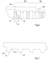
- Fig. 6 shows schematically the inclination of the sealing lips 32. It can be seen that the direction of the longitudinal extension 38 is inclined to the radius 40 by an angle 42.
- the angle 42 is preferably between 1° and 45°.
- inclined sealing lips 32a and non-inclined sealing lips 32a it is possible for inclined sealing lips 32a and non-inclined sealing lips 32a to alternate with one another.
- the inclined sealing lips 32a are preferably tapered, whereas the non-inclined sealing lips 32a are round/spherical.
- At least four sealing lips 32a can be provided in the first sealing area 28a, with inclined sealing lip 32a alternating from the first end face 22 with non-inclined sealing lip 32a. That is, in the longitudinal axis 20, the sealing lips 32a are inclined/not inclined/inclined/not inclined. Such an intermittent sequence is preferred for the first sealing area 28a.
- the number of sealing lips is in particular an even number.
- the order of the sealing lips 32b can be different, in particular a non-inclined sealing lip 32b can be followed by an inclined sealing lip 32b, which in turn is followed by a non-inclined sealing lip 32b.
- the number of sealing lips 32b in the second sealing area 28b can in particular be odd.
- the outer sealing lips 32b can be round/spherical and not inclined.
- Fig. 7 shows an enlargement of the sealing lips 32.
- An inclined sealing lip 32' can be tapered and have a first side wall 32'a that is longer than a second side wall 32'b.
- a second sealing lip 32" can be round/spherical in cross-sectional profile, as in the Fig. 7 is shown.
- the grommet 6 In a cross section, perpendicular to the longitudinal axis 20, the grommet 6 has a continuous opening with a clear opening.
- the 18/16 cable is inserted into this clear opening (clear width).
- the sealing lips form a receiving profile/a clear opening into which the cable 16/18 can be inserted.
- Fig. 8a shows a top view parallel to the longitudinal axis 20 of a sealing lip 32, which has two long sides 44 and two broad sides 46.
- the long sides 44 like the broad sides 46, run parallel to one another and merge into one another in a radius 48. This can be, for example, the sealing lip 32' or the sealing lip 32".
- the other sealing lip 32', 32" is in the Fig. 8b shown.
- the long sides 44 are curved inwards towards each other and the broad sides 46 are also curved inwards towards each other.
- the transitions between the long sides 44 and the broad sides 46 are formed by radii 48 that are smaller than the radii 48 according to FIG Fig. 8a .
Landscapes
- Engineering & Computer Science (AREA)
- Architecture (AREA)
- Civil Engineering (AREA)
- Structural Engineering (AREA)
- Mechanical Engineering (AREA)
- Installation Of Indoor Wiring (AREA)
- Cable Accessories (AREA)
- Gasket Seals (AREA)
Description
- Der Gegenstand betrifft eine Dichtung für ein elektrisches Kabel sowie ein Gehäuse mit einer solchen Dichtung.
- Die Abdichtung elektrischer Kabel, insbesondere in automotiven Anwendungen, hat enorme Relevanz für die Haltbarkeit der elektrischen Installation. Gerade in automotiven Anwendungen, in denen der Verkabelungsaufwand stetig steigt, werden hohe Anforderungen an die Abdichtungen von Kabeleinführungen in Gehäuse gestellt. Dies liegt an der einerseits dynamischen Belastungssituation der Kabeleinführung in die Gehäuse und andererseits an der hohen Belastung durch korrosive Stoffe, wie beispielsweise salzhaltiges Wasser. Es muss verhindert werden, dass längs des Kabels Feuchtigkeit durch die Dichtung in ein Gehäuse gelangt und die dort angeordnete elektrische(n) Verbindung(en) angreift.
- Der zunehmende Verkabelungsaufwand führt dazu, dass unterschiedlichste Kabelgeometrien gleichzeitig in einem Fahrzeug eingebaut werden. So ist es durchaus denkbar, dass in einem Bordnetz eines Kraftfahrzeugs neben Rundleitern gleichzeitig Flachleiter verbaut sind. Rund- und Flachleiter haben unterschiedlichste Querschnittsgeometrien, müssen jedoch gleichsam dicht in ein Gehäuse eingeführt werden können.
- Die Veröffentlichung
EP 3 279 537 A1 zeigt ein Dichtungselement, das eine Abweichung der Ausrichtung oder Anordnung von Elementen, z.B. einer Behandlungsvorrichtung für elektrolytische oder nasschemische Behandlung, ausgleicht. - Die Veröffentlichung
EP 0 823 763 A1 betrifft eine Tülle zum Abdichten einer Öffnung in einer Platte, durch die mindestens ein Kabel verläuft, und insbesondere eine Tülle, die in der Automobilindustrie zum Abdichten einer Öffnung in einer Platte verwendet wird, die den Motorraum vom Fahrgastraum gegen Wasser, Hitze und Schmutz trennt und durch die mindestens ein Kabel oder eine Verkabelung verläuft. - Die Veröffentlichung
US 5 155 303 A betrifft einen Kabelverschluss, der mindestens eine Tülle mit verbesserter Dichtungsfähigkeit umfasst. - Die Veröffentlichung
US 6 438 828 B1 bezieht sich auf eine Anordnung und ein Verfahren zum Abdichten eines Kabelbaums, der durch eine Tülle verläuft, die in einem Durchgangsloch in einer Platte eines Kraftfahrzeugs installiert ist. - Die Veröffentlichung
JP H 08 107620 A - Die Veröffentlichung
CN 210 830 473 U gehört zum technischen Gebiet der Motorwellendichtungen, insbesondere zu einer Motorwellendichtung. - Ausgehend von diesem Stand der Technik lag dem Gegenstand die Aufgabe zugrunde, eine Dichtung zur Verfügung zu stellen, welche bei unterschiedlichsten Kabelgeometrien eine sichere Dichtung gegenüber Eintritt von Längswasser ermöglicht.
- Diese Aufgabe wird durch eine Dichtung nach Anspruch 1 sowie ein Gehäuse nach Anspruch 14 gelöst.
- Die gegenständliche Dichtung als auch das gegenständliche Gehäuse wird insbesondere in automotiven Bordnetzen eingesetzt. Automotive Bordnetze sind insbesondere Bordnetze von Kraftfahrzeugen, insbesondere von Pkw oder Lkw, jedoch auch Zweiräder und andere motorisch betriebene Fahrzeuge.
- Das elektrische Kabel hat in der Regel eine metallische Kabelseele, welche aus Vollmaterial oder aus Litzen gebildet ist und einen diese Seele umgebenden Isolator. Ein elektrisches Kabel wird zur Kontaktierung mit weiteren Kabeln oder elektrischen Bauteilen in der Regel stirnseitig abisoliert. Das dann blanke Metall der Kabelseele wird mit dem anderen Bauteil verbunden, insbesondere formschlüssig und/oder stoffschlüssig durch beispielsweise Verschrauben, Verlöten, Verschweißen oder dergleichen. Der Übergang zwischen den beiden metallischen Bauteilen ist vor Korrosion zu schützen.
- Häufig ist ein solcher Übergang innerhalb eines Gehäuses, welches an sich wasserdicht ist. Jedoch stellt die Einführung des Kabels in das Gehäuse eine Herausforderung hinsichtlich der Wasserdichtigkeit dar. Ein elektrisches Kabel wird mit seinem Isolator in der Regel durch eine Tülle in ein Gehäuse eingeführt. Die Tülle hat einen Durchgangskanal, durch den sich das Kabel erstreckt. Der Durchgangskanal einer Tülle erstreckt sich von einer ersten Stirnseite hin zu einer zweiten Stirnseite der Tülle. Dieser Durchgangskanal ist umschrieben durch eine innere Mantelfläche der Tülle. Diese innere Mantelfläche dient in der Regel zur Abdichtung des Kabels.
- Bekannt ist es beispielsweise, eine Tülle oder einen Schrumpfschlauch so zu dimensionieren, dass diese an den Leitungsquerschnitt des Kabels samt Isolator angepasst sind und das Kabel in einer Presspassung in die Tülle eingeschoben wird. Dies funktioniert natürlich nur für ein Kabel einer bestimmten Querschnittsgeometrie.
- Um gegenüber einem Schrumpfschlauch verbesserte Dichtwirkung zu erreichen, weist eine Tülle in der Regel zumindest zwei in Längsrichtung voneinander beabstandete, an der inneren Mantelfläche der Tülle angeordnete, nach innen weisende Dichtlippen auf. Die Dichtlippen sind bevorzugt vollständig umlaufend und liegen eng an dem Kabel an. Die Dichtlippen ermöglichen es, dass sich die innere lichte Weite der Tülle an verschiedene Kabelquerschnitte anpassen kann. Die Dichtlippen haben in etwa gleiche Materialstärken wie der Rest der Mantelfläche und sind elastisch verformbar. Die Dichtlippen weisen radial nach innen weisen. Die Dichtlippen können sich besser elastisch radial nach außen verformen als die Mantelfläche der Tülle selbst. Dadurch liegen die Dichtlippen enger an dem Kabel an als nur eine gewöhnliche Tülle. Dies gilt insbesondere bei Unregelmäßigkeiten am Außenumfang des Kabels, bei denen die Dichtlippen nach wie vor eine Dichtwirkung ermöglichen.
- Aber auch diese Maßnahmen reichen nicht immer aus, so dass dem Gegenstand die Aufgabe zugrunde lag, ausgehend von bekannten Dichtungen die Dichtwirkung zu verbessern.
- Diese Aufgabe wird unter Berücksichtigung der Merkmale des Oberbegriffs durch eine Dichtung nach Anspruch 1 sowie ein Gehäuse nach Anspruch 14 gelöst.
- Für eine gegenüber herkömmlichen Tüllen optimierte Dichtwirkung, aber auch für eine Anpassung der Dichtung an verschiedenartige Kabelquerschnitte des zu dichtenden Kabels, weist die gegenständliche Tülle zumindest zwei in Längsrichtung nebeneinander angeordnete, durch einen umlaufenden Trennbereich voneinander beabstandete Dichtbereiche auf. Diese beiden Dichtbereiche sind an den jeweiligen Stirnseiten der Tülle angeordnet, wobei ein erster Dichtbereich der Dichtbereiche der ersten Stirnseite zugewandt ist und ein zweiter Dichtbereich der Dichtbereiche der zweiten Stirnseite zugewandt ist. Durch den Trennbereich, der eine geringere Wandstärke der Mantelfläche der Tülle aufweist als die Mantelfläche der Tülle in den Dichtbereichen, wird erreicht, dass sich bei dynamischen Belastungen die Dichtbereiche relativ zueinander bewegen können, ohne dass eine Bewegung in dem ersten Dichtbereich zu einer maßgeblichen Beeinträchtigung der Dichtwirkung in dem zweiten Dichtbereich führt und/oder umgekehrt. Die Wandstärke bezieht sich auf die Tülle, insbesondere die Wandstärke der Mantelfläche der Tülle, insbesondere der Abstand zwischen innerer und äußerer Mantelfläche der Tülle. Die geringere Wandstärke führt dazu, dass im Trennbereich eine erhöhte Elastizität der Tülle gegeben ist. Diese erhöhte Elastizität ermöglicht es, dass die Bereiche sowohl in Längsrichtung als auch radial zur Längsrichtung gegeneinander beweglich sind.
- Gemäß einem Ausführungsbeispiel wird vorgeschlagen, dass der Trennbereich durch eine umlaufende, radial nach innen weisende Nut gebildet ist. Diese Nut ist an der äußeren Mantelfläche der Tülle angebracht und grenzt den ersten von dem zweiten Dichtbereich ab. Durch die Nut wird die Wandstärke der Tülle im Bereich des Nutgrundes gegenüber zumindest Teile das Rests der Tülle verringert, so dass die Tülle im Bereich der Nut flexibler ist, als im Bereich abseits der Nut. Es wird vorgeschlagen, dass die Nut eine Hohlkehle ist.
- Gemäß einem Ausführungsbeispiel wird vorgeschlagen, dass die Nut ausgehend von dem ersten Dichtbereich durch eine radial nach innen verlaufende erste Flanke hin zu dem zweiten Dichtbereich durch eine radial nach außen verlaufenden Flanke gebildet ist. Die Flanken bilden die Nutwände. Die äußere Mantelfläche erstreckt sich im ersten Dichtbereich zunächst im Wesentlichen parallel zur Längsachse der Tülle. Hin zur Nut verläuft die äußere Mantelfläche dann entlang der ersten Flanke zumindest teilweise radial nach innen. Ausgehend vom Nutgrund verläuft die äußere Mantelfläche entlang der zweiten Flanke radial nach außen hin zu dem zweiten Dichtbereich, in dem sich die äußerste Mantelfläche im Wesentlichen wieder parallel zur Längsachse der Tülle erstreckt.
- Für eine besonders gute Elastizität der beiden Dichtbereiche relativ zueinander wird vorgeschlagen, dass die erste Flanke um einen größeren Winkel zur Längsachse geneigt ist als die zweite Flanke.
- Gemäß einem Ausführungsbeispiel wird vorgeschlagen, dass in jedem der Dichtbereiche Dichtlippen angeordnet sind. Wie eingangs bereits erläutert, sind an der inneren Mantelfläche der Tülle radial nach innen weisende Dichtlippen vorgesehen. Jeder der Dichtbereiche hat zumindest eine, bevorzugt zumindest zwei solcher Dichtlippen. Durch die Verjüngung im Trennbereich können die Dichtbereiche gegeneinander schwingen. Ist in jedem der Dichtbereiche jeweils zumindest eine Dichtlippe angeordnet, kann eine verbesserte Dichtigkeit gegenüber Längswassereintritt erzielt werden.
- Um zu gewährleisten, dass sich die Tülle am Kabel an der zweiten Stirnseite besonders eng anschmiegt, wird vorgeschlagen, dass sich die Wandstärke des zweiten Dichtbereichs in Richtung der zweiten Stirnseite verjüngt. Diese dann geringere Wandstärke führt zu einer höheren elastischen Flexibilität und somit einer besseren Anschmiegung der inneren Mantelfläche des zweiten Dichtbereichs an den Außenumgang des in der Tülle angeordneten Kabels.
- Gemäß einem Ausführungsbeispiel wird vorgeschlagen, dass eine radial nach innen verlaufende Längsachse der Dichtlippen gegenüber einer senkrecht zu der Längsachse verlaufenden Querebene geneigt ist. Die Dichtlippen haben eine radiale, nach innen verlaufende Längserstreckung. Die Achse dieser Längserstreckung ist gegenüber einem Radius, der senkrecht zur Längsachse verläuft, geneigt. Dabei ist die Neigung insbesondere derart, dass die Dichtlippen in Richtung der zweiten Stirnseite geneigt sind. Diese Neigung der Dichtlippen gegenüber dem Radius ermöglicht es, dass die Dichtlippen mit einer größeren Auflagefläche an dem eingeschobenen Kabel anliegen. Eine besonders hohe Dichtigkeit gegenüber Längswassereintritt sowohl für Flachkabel als auch für Rundkabel wird erfindungsgemäß dadurch erreicht, dass zwei in Längsrichtung nebeneinander angeordnete Dichtlippen voneinander verschiedene Querschnittsprofile aufweisen. In einem Querschnitt durch die Dichtlippen in einer Ebene, die sich entlang der Längserstreckung der Dichtlippe und der Längsachse der Tülle aufspannt, können zwei nebeneinander angeordnete Dichtlippen voneinander unterschiedliche Querschnittsprofile aufweisen. Die unterschiedlichen Querschnittsprofile führen dazu, dass bei den unterschiedlichsten, häufig dynamischen Belastungssituationen stets zumindest eine der Dichtlippen eng an dem Kabel anliegt und so eine Dichtigkeit gewährleistet. Je nach Belastung des Kabels, sei es durch Biegung, Torsion, Scherung oder dergleichen, kann das Querschnittsprofil der Dichtlippe relevant für die Dichtigkeit dieser sein. Sind zwei nebeneinander angeordnete Dichtlippen mit unterschiedlichen Querschnittsprofilen gebildet, so ergibt sich eine optimierte Dichtigkeit.
- Wie zuvor erläutert, sind die Dichtlippen gegenüber einer senkrecht zu der Längsachse verlaufenden Achse geneigt. Für eine besonders gute Dichtigkeit, insbesondere in Kombination mit unterschiedlichen Kabelquerschnitten, wird auch erfindungsgemäß definiert, dass zwei in Längsrichtung der Tülle nebeneinander angeordnete Dichtlippen voneinander verschieden zu der Querebene geneigt sind. Insbesondere ist der Neigungswinkel abwechselnd, so dass intermittierend jeweils einer von zumindest zwei Neigungswinkeln an den Dichtlippen realisiert ist.
- Die unterschiedlichen Querschnittsprofile sind gemäß einem Ausführungsbeispiel derart, dass zumindest eine der Dichtlippen ein spitzzulaufendes Querschnittsprofil aufweist und dass zumindest eine der Dichtlippen ein bogenförmiges Querschnittsprofil aufweist. Jedes dieser Querschnittsprofile kann jeweils in einer n-ten Dichtlippe (n>=2) realisiert sein. Bogenförmig kann auch als ballig verstanden werden und spitz kann auch als pfeilförmig verstanden werden.
- Gemäß einem Ausführungsbeispiel wird vorgeschlagen, dass sich eine jeweilige der Dichtlippen hin zu einer Stirnfläche erstreckende Seitenwände aufweist. Die Seitenwände erstrecken sich in Längserstreckung der Dichtlippe und verlaufen im Wesentlichen parallel zueinander. Es ist jedoch bevorzugt, dass die Länge der Seitenwände voneinander verschieden ist, wobei bevorzugt die der ersten Stirnseite zugewandte Seitenwand länger ist, als die der zweiten Stirnseite zugewandte Seitenwand. Durch diese unterschiedliche Gestaltung der Seitenwände, wird eine Neigung der Dichtlippen hin zu der zweiten Stirnseite erreicht. Die Dichtlippen liegen so bevorzugt mit ihrer der ersten Stirnseite zugewandten Seitenwand auf dem Kabel auf und dichten dies ab.
- Gemäß einem Ausführungsbeispiel wird vorgeschlagen, dass eine jeweilige der Dichtlippen eine lichte Öffnung in dem Durchgangskanal aufspannt. In einem Querschnitt senkrecht zur Längsachse bilden die Dichtlippen den Durchgangskanal mit einer lichten Öffnung der Tülle. Die lichte Öffnung ist die Fläche, die in dem Durchgangskanal für das Kabel frei ist. Das Kabel wird in den Durchgangskanal eingeschoben. Bevorzugt unterscheidet sich die lichte Öffnung des Durchgangskanals im unverbauten Zustand der Tülle vom Querschnittsprofil des aufzunehmenden Kabels. Wird das Kabel in die lichte Öffnung eingeschoben, so verformt sich die Tülle elastisch und die Dichtlippen werden an den Außenumfang des Kabels angedrückt. Bevorzugt ist der Umfang der lichten Öffnung des Durchgangskanals kleiner als der Außenumfang des aufzunehmenden Kabels.
- Die lichte Öffnung wird bevorzugt durch zwei einander gegenüberliegende Längsseiten und zwei aneinander gegenüberliegende Querseiten der Dichtlippe aufgespannt. D.h. dass die lichte Öffnung bevorzugt nicht rund oder oval ist, sondern im Wesentlichen rechteckig, wobei in dem jeweiligen Ecken Radien gebildet sein können, um eine besonders gute Anpassung der Dichtlippen an das aufzunehmende Kabel zu ermöglichen.
- Wie bereits erläutert, ist die lichte Öffnung im Wesentlichen rechteckig, wobei an den Ecken Radien gebildet sein können. Hierzu wird insbesondere vorgeschlagen, dass ein Übergang zwischen einer Längsseite und einer Querseite einen Innenradius aufweist. Ein solcher Innenradius sollte in der Regel kleiner sein, als ein Außenradius des abzudichtenden Gegenstücks/Kabels.
- Gemäß einem Ausführungsbeispiel wird vorgeschlagen, dass zumindest eine der Längsseiten radial nach innen gewölbt ist und/oder dass zumindest eine der Querseiten radial nach innen gewölbt ist. Zumindest eine Längs- und oder zumindest eine Querseite kann radial nach innen gewölbt sein. Eine Dichtlippe mit nach innen gewölbten Seiten kann sich abwechseln mit einer Dichtlippe mit parallel zueinander verlaufenden Seiten.
- Zwischen dem ersten Dichtbereich und der ersten Stirnseite kann an der Tülle ein Faltenbalg angeordnet sein, um eine Bewegung der Tülle relativ zu dem die Tülle aufweisenden Gehäuse zu ermöglichen.
- Zur Abdichtung der Tülle an einem Gehäuse wird vorgeschlagen, dass an der ersten Stirnseite ein radial nach außen verlaufender Flansch angeordnet ist. Der Flansch kann an dem Gehäuse angeordnet und mit der Gehäusewand verpresst werden. Durch den Flansch kann eine Aufnahme/Öffnung in dem Gehäuse gegenüber der Tülle abgedichtet werden.
- Ein weiterer Aspekt ist ein Gehäuse mit einer zuvor beschriebenen Dichtung. Dieses Gehäuse hat eine Aufnahme/Öffnung zur Aufnahme eines Kabels. An dieser Aufnahme kann eine gegenständliche Tülle angeordnet sein, wobei diese von dem Gehäuse abstehend nach außen oder in das Gehäuse weisend nach innen an der Aufnahme angeordnet sein kann.
- Gemäß einem Ausführungsbeispiel wird vorgeschlagen, dass der Flansch der Tülle zwischen einer Gehäusewand und einem Klemmelement verklemmt ist. Hierdurch wird die Tülle gegenüber dem Gehäuse abgedichtet. Der Flansch kann an der Innenseite des Gehäuses oder bevorzugt an der Außenseite des Gehäuses an der Gehäusewand anliegen und gegen diese gepresst sein. Der Flansch kann eine Abdichtung der Tülle gegenüber der Aufnahme gewährleisten.
- Ein weiterer Aspekt ist ein System mit einem zuvor beschriebenen Gehäuse. Bei diesem System sind zumindest zwei Aufnahmen vorgesehen und jeweils an einer der Aufnahme angeordnete Dichtungen. Die Dichtungen sind so gebildet, dass eine erste Dichtung ein Rundkabel und eine zweite Dichtung ein Flachkabel dichtend aufnimmt.
- Nachfolgend wird der Gegenstand anhand einer Ausführungsbeispiele zeigenden Zeichnung näher erläutert. In der Zeichnung zeigen:
- Fig. 1a, b
- Ein Gehäuse mit einer Dichtungen gemäß Ausführungsbeispielen;
- Fig. 2
- Eine Dichtung mit Tüllen gemäß Ausführungsbeispielen;
- Fig. 3a-c
- Dichtungen mit Tüllen und eingeschobenen Kabeln gemäß Ausführungsbeispielen;
- Fig. 4a, b
- Einen Längsschnitt durch eine Tülle gemäß einem Ausführungsbeispiel;
- Fig. 5
- Eine Detailansicht einer Tülle gemäß einem Ausführungsbeispiel;
- Fig. 6
- Eine schematische Darstellung von Dichtlippen gemäß einem Ausführungsbeispiel;
- Fig. 7
- Eine Detailansicht von Dichtlippen gemäß einem Ausführungsbeispiel;
- Fig. 8a, b
- Eine lichte Öffnung der Dichtlippen in einem Querschnitt gemäß einem Ausführungsbeispiel.
-
Fig. 1a zeigt ein Gehäuse 2. Das Gehäuse 2 kann beispielsweise ein Gehäuse eines elektrischen Anbauteils, ein Sicherungskasten, ein Verteilkasten, insbesondere für automotive Anwendungen oder dergleichen sein. Das Gehäuse 2 kann zur Aufnahme von Kabeln mit einer Dichtung 4 gebildet sein. Zur Aufnahme von Kabeln hat das Gehäuse 2 zumindest eine Öffnung 8, an der die Dichtung 4 angeordnet ist. Die Dichtung 4 kann eine oder mehrere Tüllen 6 aufweisen. Die Tüllen 6 sind unmittelbar an einer jeweiligen Öffnung 8 angeordnet. - In diesem Zusammenhang sei erwähnt, dass nachfolgend überwiegend Dichtungen 4 mit zwei Tüllen 6 gezeigt sind, dies jedoch rein beispielhaft ist. Dichtungen 4 mit einer Tülle 6 oder mehr als zwei Tüllen 6 fallen selbstverständlich unter den Gegenstand und alle hier gezeigten Ausführungsbeispiele gelten für entsprechende Anzahlen von Tüllen 6.
- In der
Fig. 1a ist gezeigt, dass die Tüllen 6 an den Öffnungen 8 nach außen weisend angeordnet sind, d.h., dass sie sich von dem Gehäuse 2 weg erstrecken. Die Anordnung der Dichtung 4 an dem Gehäuse 2 erfolgt über eine klemmende Aufnahme eines Flansches der Dichtung 4, wie nachfolgend noch gezeigt werden wird. Durch die Tüllen 6 kann jeweils ein Kabel mit seiner Isolation gesteckt werden und so durch die Öffnung 8 in das Innere des Gehäuses 2 geführt sein. -
Fig. 1b zeigt ein weiteres Ausführungsbeispiel eines Gehäuses 2, bei dem jedoch die Tüllen 6 nach innen weisend am dem Gehäuse 2 angeordnet sind. Eine Kombination von Tüllen 6, die sowohl nach innen als auch nach außen weisend an verschiedenen Öffnungen 8 eines einzigen Gehäuse 2 angeordnet sind, ist ebenfalls möglich. Die Tüllen 6 der Dichtung 4 sind so konzipiert, dass sie eine besonders gute Dichtigkeit gegenüber Längswasser aufweisen und sowohl Flachkabel aus auch Rundkabel dichtend aufnehmen können. -
Fig. 2 zeigt eine Dichtung 4 in einem unbelasteten Zustand (ohne Kabel), so dass die Tüllen 6 der Dichtung 4 unbelastet und nicht verformt sind. Zu erkennen ist, dass die Tüllen 6 in einem Flansch 10 münden. Der Flansch 10 kann auf seiner Oberfläche in Richtung der Tüllen 6 weisende Vorsprünge 12 oder Rücksprünge aufweisen. Auch können auf der nicht gezeigten Oberfläche des Flansches 10 entsprechende Vorsprünge 12 vorgesehen sein. Die Tüllen 6 erstrecken sich ausgehend vom Flansch 10, in den sie in einer ersten (nicht gezeigten) Stirnseite münden, hin zu einer zweiten Stirnseite 14. Die Tüllen 6 haben dabei eine umlaufende Mantelfläche. Die Tülle spannt eine Durchgangsöffnung mit einer lichten Öffnung auf, in die, wie nachfolgend noch gezeigt werden wird, ein Kabel eingesteckt werden kann. Die Dichtung 4 wird so an einem Gehäuse 2 platziert, dass die Tüllen 6 an Öffnungen 8 angeordnet sind. Anschließend wird die Dichtung 4 mit einem Klemmelement (nicht gezeigt) gegenüber dem Gehäuse 2 verpresst. Der Flansch 10 wird zwischen dem Klemmelement und dem Gehäuse 2 eingeklemmt, so dass der Flansch 10 eine Dichtigkeit gegenüber der Öffnung 8 bildet. Die Durchgangsöffnung der Tüllen 6 wird genutzt, um ein Kabel in das Gehäuse 2 hinein zu schieben. -
Fig. 3a zeigt die Dichtung 4 gemäß derFig. 2 , bei der ein Flachkabel 16 in eine der Tüllen 6 eingeschoben ist. Wie zu erkennen ist, führt das Flachkabel 16 zu einer Verformung des Querschnitts der Tülle 6. Die Tülle 6 schmiegt sich an das Flachkabel 16 an und bildet an dem Flachkabel 16, insbesondere dessen Isolation, eine längswasserdichte Abdichtung. - In der
Fig. 3b ist eine Dichtung 4 gemäß derFig. 2 gezeigt, bei der ein Rundkabel 18 in die Tülle 6 eingeschoben ist. Auch hier ist zu erkennen, dass die Tülle 6 sich mit ihrer inneren Mantelfläche an die Isolation des Rundkabels 18 anschmiegt. -
Fig. 3c zeigt ein weiteres Ausführungsbeispiel einer Dichtung 4 gemäß derFig. 2 , bei dem einerseits ein Rundkabel 18 und andererseits ein Flachkabel 16 in jeweils eine der Tüllen 6 eingeschoben ist. Zu erkennen ist, dass die Tüllen 6 zur Aufnahme verschiedenartiger Kabel 16, 18 gebildet sind, wobei gegenständlich durch die Konstruktion der Tüllen 6 eine Längswasserdichtigkeit für die verschiedensten Leitungsquerschnitte erzielt wird. - Die Tüllen 6 erstrecken sich in einer Längsrichtung entlang einer Längsachse 20, wie in der
Fig. 4a gezeigt ist.Fig. 4a zeigt einen Längsschnitt durch eine Tülle 6 entlang der Längsachse 20. Zu erkennen ist, dass sich die Tülle 6 von einer ersten Stirnseite 22 hin zu einer zweiten Stirnseite 24 erstreckt. An den Stirnseiten 22, 24 hat die Tülle 6 eine Öffnung, die sich zwischen den Stirnseiten 22, 24 durch die Tülle 6 erstreckt. An der ersten Stirnseite 22 kann der Flansch 10 radial nach außen weisend an der Tülle 6 vorgesehen sein. Die Tülle 6 erstreckt sich ausgehend von der ersten Stirnseite 22 entlang der Längsachse 20 in einem optionalen Faltenbalg 26. Ausgehend von dem Faltenbalg 26 erstreckt sich die Tülle 6 in einen ersten Dichtbereich 28a und einen zweiten Dichtbereich 28b, wobei die Dichtbereiche 28a, b durch einen Trennbereich 30 voneinander getrennt sind. - Der Trennbereich 30 zeichnet sich durch eine vorzugsweise vollständig umlaufende, oder auch nur teilweise umlaufende Verjüngung der Materialstärke der Tülle 6 aus. Insbesondere ist der Trennbereich 30 durch eine zumindest teilweise umlaufende Nut gebildet. Durch diesen Trennbereich 30 sind der erste Dichtbereich 28a und der zweite Dichtbereich 28b zumindest teilweise mechanisch entkoppelt, so dass eine Relativbewegung zwischen den Dichtbereichen 28a, b erleichtert wird. Durch diese zumindest teilweise Entkoppelung der Dichtbereiche 28a, b kann jeder Dichtbereich 28a, b eine eigene Dichtwirkung entfalten. Eine Beeinträchtigung der Dichtwirkung eines der Dichtbereiche 28a, b führt nicht unmittelbar zu einer Beeinträchtigung der Dichtwirkung des anderen Dichtbereichs 28a, b. Die Erstreckung des Trennbereichs in Längsrichtung kann so gewählt sein, dass die Nut zur Aufnahme eines Klemmrings, Kabelbinders oder dergleichen geeignet ist. Dadurch kann über die Nut im Bereich des Trennbereichs eine weitere Abdichtung erfolgen.
- In jedem der Dichtbereiche 28a, b sind an der inneren Mantelfläche der Tülle 24 in Richtung der Längsachse 20 weisende Dichtlippen 32 vorgesehen. Die Dichtlippen 32 sind in Richtung der Längsachse 20 nebeneinander beabstandet voneinander an der inneren Mantelfläche der Tülle 6 angeordnet. Die Dichtlippen 32 sind vollständig umlaufend an der inneren Mantelfläche. Im eingeschobenen Zustand eines Kabels 16, 18, wie in der
Fig. 4b zu erkennen, liegen die Dichtlippen 32 an der äußeren Isolation der Kabel 16, 18 an und bilden somit einen Schutz vor Eintritt vor Längswasser. - Die Materialstärke der Tülle 6 verjüngt sich im zweiten Dichtbereich hin zur zweiten Stirnfläche, so dass sie sich dort besonders gut an das Kabel anschmiegen kann. Die Gestaltung der Dichtlippen 30 ist in der
Fig. 5 näher dargestellt. Auch ist der Trennbereich 30 näher dargestellt. -
Fig. 5 ist eine Detaildarstellung der Tülle 6 mit den Dichtbereichen 28a, b. Die Längserstreckung der Dichtbereiche 28a, b kann voneinander verschieden sein, insbesondere kann der der zweiten Stirnseite 24 zugewandte zweite Dichtbereich 28b kürzer sein, als der erste Dichtbereich 28a. - In der
Fig. 5 ist zu erkennen, dass die äußere Mantelfläche der Tülle 6 ausgehend von der ersten Stirnseite 22 im Wesentlichen parallel zur Längsachse 20 verläuft. Im Bereich des Trennbereichs 30 kippt die äußere Mantelfläche mit einer ersten Flanke 34a radial nach innen. Der Neigungswinkel der Flanke 34a ist bevorzugt zwischen 45° und 90° zur Längsachse 20. Ausgehend von der ersten Flanke 34 erstreckt sich die äußere Mantelfläche der Tülle 6 hin zu einem Nutgrund 36. Der Nutgrund 36 stellt den Bereich der Trennstelle 30 mit der geringsten Material-/ Wandstärke der Tülle 6 dar. Ausgehend vom Nutgrund 36 verläuft eine zweite Flanke 34b radial nach außen, wobei die Flanke 34b mit einem kleineren Winkel zur Längsachse 20 angestellt ist als die erste Flanke 34a, beispielsweise zwischen 5° und 45°. - Am Ende der zweiten Flanke 34b erstreckt sich die äußere Mantelfläche der Tülle 6 bevorzugt wieder im Wesentlichen parallel zur Längsachse 20, kann jedoch auch mit einer Neigung zwischen 5° und 15° zur Längsachse 20 hin zur zweiten Stirnseite 24 verlaufen. Der Trennbereich 30 stellt eine Einschnürung der Wandstärke der Tülle 6 dar, wodurch eine mechanische teilweise Entkoppelung der Dichtbereiche 28a, b bewirkt wird.
- Jeder der Dichtbereiche 28a, b hat Dichtlippen 32a, b. Zu erkennen ist, dass die Dichtlippen 32a im ersten Dichtbereich 28a eine größere Erstreckung sowohl in Längsrichtung 20 als auch quer dazu gegenüber den Dichtlippen 32b im zweiten Dichtbereich 28b haben. Die Dichtlippen 32a, b sind entlang der Längsachse 20 beabstandet voneinander. In dem dargestellten Längsschnitt, der in einer Ebene aufgespannt durch die Längsachse 20 und einem Radius der Tülle 6 liegt, haben die Dichtlippen 32a, b jeweils abwechselnd zueinander unterschiedliche Querschnittsprofile.
- Im ersten Dichtbereich 28a wechseln sich spitze Dichtlippen 32a mit rund-/ ballförmigen Dichtlippen 32a ab. Die Dichtlippen 32a haben eine Längserstreckung in einer Erstreckungsrichtung 38. Die Erstreckungsrichtung 38 kann gegenüber einem zur Längsachse 20 verlaufenden Radius 40 um 1° bis 10° geneigt sein. Die Neigung ist bevorzugt in Richtung der ersten Stirnseite 24. Hierdurch wird eine größere Auflagefläche der Dichtlippen 32a auf dem Isolator des Kabels 16, 18 realisiert.
- Im ersten Dichtbereich 28a sind vier Dichtlippen 32a vorgesehen, jeweils zwei spitz verlaufende Dichtlippen 32a und zwei runde Dichtlippen 32a.
- Im zweiten Dichtbereich 28b können entsprechende Dichtlippen 32b mit bevorzugt kleineren Dimensionierungen, jedoch gleicher Ausrichtung und Profilform gebildet sein. In der
Fig. 5 ist zu erkennen, dass sich drei Dichtlippen 32b im Dichtbereich 38b befinden, wobei zwei runde Dichtlippen 32b eine spitz zulaufende Lippe 32b einrahmen. Auch die Dichtlippen 32b können gegenüber einem Radius 40 geneigt sein. -
Fig. 6 zeigt schematisch die Neigung der Dichtlippen 32. Zu erkennen ist, dass die Richtung der Längserstreckung 38 zum Radius 40 um einen Winkel 42 geneigt ist. Der Winkel 42 beträgt dabei bevorzugt zwischen 1° und 45°. Insbesondere ist es möglich, dass sich geneigte Dichtlippen 32a und nicht geneigte Dichtlippen 32a einander abwechseln. Die geneigten Dichtlippen 32a sind bevorzugt spitz zulaufend, wohingegen die nicht geneigten Dichtlippen 32a rund/ballig sind. - In dem ersten Dichtbereich 28a können zumindest vier Dichtlippen 32a vorgesehen sein, wobei ausgehend von der ersten Stirnseite 22 geneigte Dichtlippe 32a sich mit nicht geneigten Dichtlippe 32aabwechseln. D.h. in der Längsachse 20 sind die Dichtlippen 32a geneigt/nicht geneigt/geneigt/nicht geneigt. Eine solche intermittierende Abfolge ist bevorzugt für den ersten Dichtbereich 28a. Die Anzahl der Dichtlippen ist insbesondere geradzahlig.
- In dem zweiten Dichtbereich 28b kann die Reihenfolge der Dichtlippen 32b anders sein, insbesondere kann eine nicht geneigte Dichtlippe 32b von einer geneigten Dichtlippe 32b gefolgt sein, die wiederum von einer nicht geneigten Dichtlippe 32b gefolgt ist. Die Anzahl der Dichtlippen 32b im zweiten Dichtbereich 28b kann insbesondere ungeradzahlig sein. Die jeweils äußeren Dichtlippen 32b können rund/ballig und nicht geneigt sind.
-
Fig. 7 zeigt eine Vergrößerung der Dichtlippen 32. Eine geneigte Dichtlippe 32' kann spitz zulaufen und eine erste Seitenwand 32'a, die länger ist, als eine zweite Seitenwand 32'b, haben. Eine zweite Dichtlippe 32" kann rund/ballig im Querschnittsprofil sein, wie in derFig. 7 dargestellt ist. - In einem Querschnitt, senkrecht zur Längsachse 20 hat die Tülle 6 eine durchgehende Öffnung mit einer lichten Öffnung. In diese lichte Öffnung (lichte Weite) wird das Kabel 18/16 eingeschoben. Die Dichtlippen bilden ein Aufnahmeprofil/ eine lichte Öffnung, in die das Kabel 16/18 eingeschoben werden kann.
- Es wird insbesondere bevorzugt, dass die Dichtlippen 32 abwechselnd unterschiedliche Querschnittsprofile aufweisen. Hierbei wird insbesondere bevorzugt, dass aufeinanderfolgende Dichtlippen 32 unterschiedliche lichte Öffnungen haben, wie durch die
Fig. 8a dargestellt ist.Fig. 8a zeigt eine Draufsicht parallel zur Längsachse 20 auf eine Dichtlippe 32, die zwei Längsseiten 44 und zwei Breitseiten 46 aufweist. Die Längsseiten 44 verlaufen ebenso wie die Breitseiten 46 parallel zueinander und gehen in einem Radius 48 ineinander über. Dies kann beispielsweise die Dichtlippe 32' oder die Dichtlippe 32" sein. - Die jeweils andere Dichtlippe 32', 32" ist in der
Fig. 8b dargestellt. Hier verlaufen die Längsseiten 44 aufeinander zuweisend nach innen gewölbt und die Breitseiten 46 verlaufen ebenfalls aufeinander zuweisend nach innen gewölbt. Die Übergänge zwischen den Längsseiten 44 und den Breitseiten 46 sind durch Radien 48 gebildet, die kleiner sind als die Radien 48 gemäß derFig. 8a . - Durch die unterschiedlichen lichten Öffnungen, die einander abwechseln, gemäß der
Fig. 8a und 8b , kann insbesondere eine Längswasserdichtigkeit für Kabel mit unterschiedlichen Leitungsquerschnitten, insbesondere Rundkabel und Flachkabel gewährleistet werden. -
- 2
- Gehäuse
- 4
- Dichtung
- 6
- Tülle
- 8
- Öffnung
- 10
- Flansch
- 12
- Vorsprung
- 14
- Stirnseite
- 16
- Flachkabel
- 18
- Rundkabel
- 20
- Längsachse
- 22, 24
- Stirnseite
- 26
- Faltenbalg
- 28a, b
- Dichtbereich
- 30
- Trennbereich
- 32
- Dichtlippe
- 34a, b
- Flanke
- 36
- Nutgrund
- 38
- Längserstreckung
- 40
- Radius
- 42
- Winkel
- 44
- Längsseite
- 46
- Breitseite
- 48
- Radius
Claims (16)
- Dichtung (4) für ein elektrisches Kabel mit- einer sich in einer Längsrichtung von einer ersten Stirnseite (22) hin zu einer zweiten Stirnseite (24) erstreckenden, einen Durchgangskanal aufweisenden Tülle, wobei der Durchgangskanal durch eine innere Mantelfläche der Tülle umschlossen ist, und- zumindest zwei in Längsrichtung voneinander beabstandeten, an der inneren Mantelfläche der Tülle angeordneten, nach innen weisenden Dichtlippen (32), wobei- die Tülle zumindest zwei in Längsrichtung nebeneinander angeordnete, durch einen umlaufenden Trennbereich (30) voneinander beabstandete Dichtbereiche (28a, b) aufweist,- ein erster Dichtbereich (28a) der Dichtbereiche der ersten Stirnseite (22) zugewandt ist und ein zweiter Dichtbereich (28b) der Dichtbereiche der zweiten Stirnseite (24) zugewandt ist, und- der Trennbereich (30) eine geringere Wandstärke aufweist als die Dichtbereiche (28a, b),
dadurch gekennzeichnet,- dass zwei in Längsrichtung nebeneinander angeordnete Dichtlippen (32) voneinander verschiedene Querschnittsprofile aufweisen, insbesondere dass die Dichtlippen (32) abwechselnde Querschnittsprofile aufweisen, und/oder- dass zwei in Längsrichtung nebeneinander angeordnete Dichtlippen (32) voneinander verschieden zu der Querebene geneigt sind, insbesondere dass die Dichtlippen (32) abwechselnd geneigt sind. - Dichtung nach Anspruch 1,
dadurch gekennzeichnet,- dass der Trennbereich (30) durch eine umlaufende, radial nach innen weisende Nut gebildet ist, insbesondere dass die Nut eine Hohlkehle ist. - Dichtung nach Anspruch 2,
dadurch gekennzeichnet,- dass sich die Nut ausgehend von dem ersten Dichtbereich (28a) mit einer radial nach innen verlaufenden ersten Flanke (34a) hin zu dem zweiten Dichtbereich (28b) mit einer radial nach außen verlaufenden zweiten Flanke (34b) erstreckt, wobei die erste Flanke (34a) um einen größeren Winkel zur Längsachse (20) geneigt ist als die zweite Flanke (34b). - Dichtung nach einem der vorangehenden Ansprüche,
dadurch gekennzeichnet,- dass in jedem der Dichtbereiche (28a, b) zumindest zwei der Dichtlippen (32) angeordnet sind. - Dichtung nach einem der vorangehenden Ansprüche,
dadurch gekennzeichnet,- dass sich die Wandstärke des zweiten Dichtbereichs (28b) in Richtung der zweiten Stirnseite (24) verjüngt. - Dichtung nach einem der vorangehenden Ansprüche,
dadurch gekennzeichnet,- dass eine radial nach innen verlaufenden Längsachse der Dichtlippen (32) gegenüber einer senkrecht zu der Längsachse (20) verlaufenden Querebene geneigt sind, insbesondere dass die Dichtlippen (32) in Richtung der zweiten Stirnseite (24) geneigt sind. - Dichtung nach einem der vorangehenden Ansprüche,
dadurch gekennzeichnet,- dass zumindest eine der Dichtlippen (32) ein spitz zulaufendes Querschnittsprofil aufweist und/oder dass zumindest eine der Dichtlippen (32) ein bogenförmiges Querschnittsprofil aufweist. - Dichtung nach einem der vorangehenden Ansprüche,
dadurch gekennzeichnet,- dass eine jeweilige der Dichtlippen (32) sich hin zu einer Stirnfläche erstreckende Seitenwände aufweist, wobei eine Seitenwand (32'a) der Seitenwände, die der ersten Stirnseite (22) zugewandt ist länger ist als eine Seitenwand (32'b) der Seitenwände, die der zweiten Stirnseite (24) zugewandt ist. - Dichtung nach einem der vorangehenden Ansprüche,
dadurch gekennzeichnet,- dass eine jeweilige der Dichtlippen (32) eine lichte Öffnung in dem Durchgangskanal aufspannt, wobei die lichte Öffnung durch zwei einander gegenüberliegende Längsseiten (44) und zwei einander gegenüberliegende Querseiten (46) aufgespannt ist. - Dichtung nach Anspruch 9,
dadurch gekennzeichnet,- dass ein Übergang zwischen einer Längsseite (44) und einer Querseite(46) einen Innenradius (48) aufweist. - Dichtung nach einem der vorangehenden Ansprüche 9 oder 10,
dadurch gekennzeichnet,- dass zumindest eine der Längsseiten (44) radial nach innen gewölbt ist und/oder dass zumindest eine der Querseiten (46) radial nach außen gewölbt ist. - Dichtung nach einem der vorangehenden Ansprüche,
dadurch gekennzeichnet,- dass zwischen dem ersten Dichtbereich und der ersten Stirnseite (22) ein Faltenbalg (26) angeordnet ist. - Dichtung nach einem der vorangehenden Ansprüche,
dadurch gekennzeichnet,- dass an der ersten Stirnseite (22) ein radial nach außen verlaufender Flansch (10) angeordnet ist. - Gehäuse (2) mit einer Dichtung (4) nach einem der vorangehenden Ansprüchen und zumindest einer Öffnung zur Aufnahme von einem Kabel, wobei- die Tülle von dem Gehäuse (2) abstehend an der Öffnung angeordnet ist oder- die Tülle in das Gehäuse (2) weisend an der Öffnung angeordnet ist.
- Gehäuse nach Anspruch 13 und 14,
dadurch gekennzeichnet,- dass der Flansch (10) der Tülle zwischen einer Gehäusewand und einem Klemmelement verklemmt ist. - System mit einem Gehäuse nach Anspruch 14 mit zwei Öffnungen und zwei an einer jeweiligen der Öffnungen angeordneten Dichtungen (4), wobei eine Tülle einer ersten der Dichtungen (4) ein Rundkabel aufnimmt und eine Tülle einer zweiten der Dichtungen (4) ein Flachkabel aufnimmt.
Applications Claiming Priority (2)
| Application Number | Priority Date | Filing Date | Title |
|---|---|---|---|
| DE102020004934.6A DE102020004934A1 (de) | 2020-08-13 | 2020-08-13 | Dichtung für ein elektrisches Kabel |
| PCT/EP2021/068844 WO2022033776A1 (de) | 2020-08-13 | 2021-07-07 | Dichtung für ein elektrisches kabel |
Publications (2)
| Publication Number | Publication Date |
|---|---|
| EP4197074A1 EP4197074A1 (de) | 2023-06-21 |
| EP4197074B1 true EP4197074B1 (de) | 2024-02-28 |
Family
ID=76971858
Family Applications (1)
| Application Number | Title | Priority Date | Filing Date |
|---|---|---|---|
| EP21743104.8A Active EP4197074B1 (de) | 2020-08-13 | 2021-07-07 | Dichtung für ein elektrisches kabel |
Country Status (7)
| Country | Link |
|---|---|
| US (1) | US11881331B2 (de) |
| EP (1) | EP4197074B1 (de) |
| CN (1) | CN116157301B (de) |
| DE (1) | DE102020004934A1 (de) |
| ES (1) | ES2983256T3 (de) |
| MX (1) | MX2023001798A (de) |
| WO (1) | WO2022033776A1 (de) |
Families Citing this family (5)
| Publication number | Priority date | Publication date | Assignee | Title |
|---|---|---|---|---|
| DE102020004934A1 (de) * | 2020-08-13 | 2022-02-17 | Auto-Kabel Management Gmbh | Dichtung für ein elektrisches Kabel |
| JP7505368B2 (ja) * | 2020-10-28 | 2024-06-25 | 住友電装株式会社 | グロメット |
| KR20230153005A (ko) * | 2022-04-28 | 2023-11-06 | 콘티넨탈 오토모티브 게엠베하 | 차량용 그로밋 장치 |
| DE102023103874A1 (de) * | 2023-02-16 | 2024-08-22 | Carl Freudenberg Kg | Dichtungsanordnung und deren Verwendung |
| JP2025062465A (ja) * | 2023-10-02 | 2025-04-14 | 日本航空電子工業株式会社 | シール構造体 |
Citations (3)
| Publication number | Priority date | Publication date | Assignee | Title |
|---|---|---|---|---|
| EP0823763B1 (de) * | 1996-08-09 | 1999-11-03 | Sumitomo Wiring Systems, Ltd. | Durchführungshülle |
| DE4341384C2 (de) * | 1992-12-17 | 2002-12-12 | Volkswagen Ag | Durchführung von Leitungen |
| CN210830473U (zh) * | 2019-06-25 | 2020-06-23 | 常州绍鼎密封科技有限公司 | 一种电机轴封 |
Family Cites Families (68)
| Publication number | Priority date | Publication date | Assignee | Title |
|---|---|---|---|---|
| US2996567A (en) * | 1959-01-27 | 1961-08-15 | William H Channell | Cable splice enclosure |
| US4232184A (en) * | 1979-03-14 | 1980-11-04 | Bell Telephone Laboratories, Incorporated | Cable adapter for converting a cable closure nozzle to a two cable entrance |
| GB9107864D0 (en) * | 1991-04-12 | 1991-05-29 | Raychem Sa Nv | Environmental sealing |
| US5155303A (en) * | 1991-05-17 | 1992-10-13 | At&T Bell Laboratories | Cable closure including grommet having enhanced sealing capability |
| ES2102126T3 (es) * | 1993-12-22 | 1997-07-16 | Rxs Schrumpftech Garnituren | Manguito para cables, compuesto de una carcasa partida longitudinalmente. |
| JP2990487B2 (ja) * | 1994-10-05 | 1999-12-13 | 矢崎総業株式会社 | グロメットの防水構造 |
| US5886300A (en) * | 1996-04-30 | 1999-03-23 | The Whitaker Corporation | Plug for a sealing grommet |
| JP3417324B2 (ja) * | 1999-01-14 | 2003-06-16 | 住友電装株式会社 | ワイヤハーネスのグロメット装着部の防水構造および防水方法 |
| DE10009686A1 (de) * | 1999-03-01 | 2000-09-07 | Witaker Corp Wilmington | Kabeldurchführung und Block für eine solche Kabeldurchführung |
| JP2000274256A (ja) * | 1999-03-23 | 2000-10-03 | Isuzu Motors Ltd | エンジンのインジェクタハーネス配線装置 |
| US6218620B1 (en) * | 1999-05-19 | 2001-04-17 | John M. Michel | Housing for telephone splices and the like and method |
| DE10047715A1 (de) * | 2000-09-25 | 2002-04-18 | Murrplastik Gmbh System Techni | Kabeldurchführung |
| DE102005016340B3 (de) * | 2005-04-09 | 2006-08-10 | Adc Gmbh | Vorrichtung und Verfahren zur universellen Kabeldurchführung |
| KR20070009910A (ko) * | 2005-07-16 | 2007-01-19 | 현대자동차주식회사 | 자동차용 그로밋의 장착 구조 |
| DE102005052832A1 (de) * | 2005-11-05 | 2007-05-10 | Audi Ag | Tülle zum Abdichten eines durch eine Wand verlaufenden Bauteiles |
| DE102006042368B4 (de) * | 2006-09-08 | 2016-01-07 | Robert Bosch Gmbh | Sammeldichtung aus mehreren Einzeldichtelementen und Kontaktanordnung für eine mehrpolige elektrische Steckverbindung |
| DE102007015110A1 (de) * | 2007-03-29 | 2008-10-02 | Volkswagen Ag | Dichtendes Durchführungsteil für Leitungen und Kabel |
| DE202008002616U1 (de) * | 2008-02-23 | 2008-04-24 | ERÜ Kunststofftechnik GmbH | Feinmechanische Vorrichtung |
| JP5098826B2 (ja) * | 2008-06-03 | 2012-12-12 | 住友電装株式会社 | グロメット |
| JP5098827B2 (ja) * | 2008-06-03 | 2012-12-12 | 住友電装株式会社 | グロメット |
| JP5098828B2 (ja) * | 2008-06-03 | 2012-12-12 | 住友電装株式会社 | グロメット |
| DE102008002616A1 (de) | 2008-06-24 | 2009-12-31 | Robert Bosch Gmbh | Kabeltülle für Handwerkzeugmaschine |
| WO2010052588A2 (en) * | 2008-11-06 | 2010-05-14 | Miretti Angelo B | Connector apparatus and system for explosion proof engine |
| DE102009008506B3 (de) * | 2009-02-12 | 2010-08-26 | Airbus Deutschland Gmbh | Kabelanschlussvorrichtung, damit versehene Leitungsdurchführung sowie Verwendung der selben |
| DE102009002001A1 (de) * | 2009-03-31 | 2010-10-07 | Robert Bosch Gmbh | Dichtung für senkrechte Durchführung eines Getriebesteckers |
| US8507798B2 (en) * | 2009-08-21 | 2013-08-13 | Upsite Technologies, Inc. | Sealing grommet |
| JP4998527B2 (ja) * | 2009-09-08 | 2012-08-15 | 株式会社豊田自動織機 | 電動圧縮機 |
| ES2555497T3 (es) * | 2009-10-27 | 2016-01-04 | Tyco Fire Products Lp | Sistemas y métodos para acoplamientos de cañerías |
| JP5359961B2 (ja) * | 2010-03-30 | 2013-12-04 | 住友電装株式会社 | グロメット及びグロメットの防水構造 |
| CN101936302B (zh) * | 2010-09-07 | 2012-10-10 | 宁波巨神制泵实业有限公司 | 潜水电泵的电缆干式出线装置 |
| JP2012175716A (ja) * | 2011-02-17 | 2012-09-10 | Sumitomo Wiring Syst Ltd | ワイヤハーネスの保護具 |
| JP5617706B2 (ja) * | 2011-03-14 | 2014-11-05 | 住友電装株式会社 | グロメットのシール構造 |
| WO2012162497A1 (en) * | 2011-05-24 | 2012-11-29 | Corning Cable Systems Llc | Three-cable port grommet washer |
| GB201110984D0 (en) * | 2011-06-28 | 2011-08-10 | Airbus Operations Ltd | Split grommet assembly |
| JP2013048509A (ja) * | 2011-08-29 | 2013-03-07 | Sumitomo Wiring Syst Ltd | ハーネス保護具及びワイヤーハーネス配索構造部 |
| DE102011089515A1 (de) * | 2011-12-22 | 2013-06-27 | Bayerische Motoren Werke Aktiengesellschaft | Tülle zum Durchführen wenigstens einer Leitung |
| DE102012105290A1 (de) * | 2012-06-18 | 2013-12-19 | Elastomer Solutions GmbH | Tülle |
| DE102013002445A1 (de) | 2013-02-14 | 2014-08-14 | Sew-Eurodrive Gmbh & Co Kg | Vorrichtung mit Dichtelement zur Kabeldurchführung |
| JP6008249B2 (ja) * | 2013-07-04 | 2016-10-19 | 住友電装株式会社 | グロメット |
| KR101496929B1 (ko) * | 2013-12-27 | 2015-03-02 | 갑을오토텍(주) | 차량용 그로밋 장치 |
| DE102014102260B4 (de) | 2014-02-21 | 2016-01-07 | Berthold Sichert Gmbh | Baukasten für die Abdichtung des Durchganges von Kabeln oder Adern, die durch eine Platte verlaufen sowie Verfahren zum Abdichten |
| JP2016015851A (ja) * | 2014-07-03 | 2016-01-28 | 住友電装株式会社 | グロメット |
| DE102014011180B4 (de) * | 2014-07-31 | 2020-09-03 | Auto-Kabel Management Gmbh | Elektrischer Flachleiter für Kraftfahrzeuge |
| DE102014115362A1 (de) * | 2014-10-22 | 2016-04-28 | Bombardier Transportation Gmbh | Kabeldurchgangsabdichtung für einen Kabelkanal, Bausatz für eine Kabeldurchgangsabdichtung und Verfahren zum Montieren einer Kabeldurchgangsabdichtung für einen Kabelkanal |
| JP6248899B2 (ja) * | 2014-11-05 | 2017-12-20 | 住友電装株式会社 | ワイヤハーネスのシール構造 |
| JP6647280B2 (ja) * | 2015-03-26 | 2020-02-14 | 古河電気工業株式会社 | グロメット及びグロメット付ワイヤーハーネス |
| DE102015118921A1 (de) * | 2015-11-04 | 2017-05-04 | Auto-Kabel Management Gmbh | Mehrspannungsbordnetzsystem sowie Spannungsebenen – übergreifendes Multilayerkabel |
| JP2017229190A (ja) * | 2016-06-24 | 2017-12-28 | 住友電装株式会社 | グロメット及びワイヤハーネス |
| EP3279537A1 (de) * | 2016-08-04 | 2018-02-07 | ATOTECH Deutschland GmbH | Flexibles dichtungselement |
| JP6642353B2 (ja) * | 2016-09-16 | 2020-02-05 | 住友電装株式会社 | グロメットの車体取付け構造 |
| JP2018078739A (ja) * | 2016-11-10 | 2018-05-17 | 住友電装株式会社 | 外装通気部材 |
| JP2018153059A (ja) | 2017-03-15 | 2018-09-27 | 住友電装株式会社 | グロメット及びグロメットの取り付け構造 |
| DE102017121459B4 (de) * | 2017-09-15 | 2024-03-14 | Auto-Kabel Management Gmbh | Kabelabdichtung sowie Anordnung mit einem Gehäuse |
| DE202018101152U1 (de) * | 2018-03-01 | 2019-06-04 | Yazaki Europe Ltd. | Dichtung für ein Kabel |
| EP3544132B1 (de) * | 2018-03-23 | 2021-08-04 | Nexans | Axial fixierbare dichtungsanordnung für eine kabeldurchführung |
| DE102018010251A1 (de) * | 2018-06-08 | 2019-12-12 | PSZ electronic GmbH | Vorrichtung zur Verbindung und/oder Fixierung von Schlauch- und Kabelsätzen |
| WO2020059392A1 (ja) * | 2018-09-19 | 2020-03-26 | 住友電装株式会社 | グロメットのシール構造 |
| JP6998915B2 (ja) * | 2019-05-09 | 2022-01-18 | 矢崎総業株式会社 | グロメット、及び、ワイヤハーネス |
| AU2020275957A1 (en) * | 2019-05-16 | 2021-12-16 | Rain Harvesting Pty Ltd | A fitting for a water tank |
| DE102019123755A1 (de) * | 2019-09-05 | 2021-03-11 | Auto-Kabel Management Gmbh | Pyrotechnische Zündpille sowie Verfahren zur Herstellung einer pyrotechnischen Zündpille |
| SE543690C2 (en) * | 2019-10-18 | 2021-06-08 | Scania Cv Ab | A grommet assembly and a vehicle comprising a power train component with a grommet assembly |
| WO2021104603A1 (en) * | 2019-11-25 | 2021-06-03 | Abb Schweiz Ag | Enclosure for electric device, and method of sealing a through opening of an enclosure |
| US11808394B2 (en) * | 2020-01-31 | 2023-11-07 | Lake Products Limited | Seal system |
| JP7117337B2 (ja) * | 2020-02-03 | 2022-08-12 | 矢崎総業株式会社 | グロメット、及び、ワイヤハーネス |
| JP7159235B2 (ja) * | 2020-02-17 | 2022-10-24 | 矢崎総業株式会社 | グロメット及びワイヤハーネス |
| JP7401851B2 (ja) * | 2020-04-21 | 2023-12-20 | 株式会社オートネットワーク技術研究所 | 車載電気部品内回路ユニット |
| DE102020002701B4 (de) * | 2020-05-06 | 2023-10-05 | Auto-Kabel Management Gmbh | Dichtungsgehäuse |
| DE102020004934A1 (de) * | 2020-08-13 | 2022-02-17 | Auto-Kabel Management Gmbh | Dichtung für ein elektrisches Kabel |
-
2020
- 2020-08-13 DE DE102020004934.6A patent/DE102020004934A1/de not_active Ceased
-
2021
- 2021-07-07 MX MX2023001798A patent/MX2023001798A/es unknown
- 2021-07-07 CN CN202180055663.1A patent/CN116157301B/zh active Active
- 2021-07-07 WO PCT/EP2021/068844 patent/WO2022033776A1/de not_active Ceased
- 2021-07-07 EP EP21743104.8A patent/EP4197074B1/de active Active
- 2021-07-07 US US18/041,208 patent/US11881331B2/en active Active
- 2021-07-07 ES ES21743104T patent/ES2983256T3/es active Active
Patent Citations (3)
| Publication number | Priority date | Publication date | Assignee | Title |
|---|---|---|---|---|
| DE4341384C2 (de) * | 1992-12-17 | 2002-12-12 | Volkswagen Ag | Durchführung von Leitungen |
| EP0823763B1 (de) * | 1996-08-09 | 1999-11-03 | Sumitomo Wiring Systems, Ltd. | Durchführungshülle |
| CN210830473U (zh) * | 2019-06-25 | 2020-06-23 | 常州绍鼎密封科技有限公司 | 一种电机轴封 |
Also Published As
| Publication number | Publication date |
|---|---|
| CN116157301A (zh) | 2023-05-23 |
| WO2022033776A1 (de) | 2022-02-17 |
| US20230245801A1 (en) | 2023-08-03 |
| EP4197074A1 (de) | 2023-06-21 |
| CN116157301B (zh) | 2024-10-18 |
| US11881331B2 (en) | 2024-01-23 |
| MX2023001798A (es) | 2023-03-10 |
| ES2983256T3 (es) | 2024-10-22 |
| DE102020004934A1 (de) | 2022-02-17 |
Similar Documents
| Publication | Publication Date | Title |
|---|---|---|
| EP4197074B1 (de) | Dichtung für ein elektrisches kabel | |
| EP3682515B1 (de) | Kabelabdichtung mit einem gehäuse sowie anordnung mit der kabelabdichtung | |
| EP3878054B1 (de) | Kontaktelement und verfahren zu dessen herstellung | |
| WO2013110490A1 (de) | Gewinkelter hochvolt-stecker | |
| DE112012003924T5 (de) | Kontakabdichtstruktur für Kabelbaum | |
| DE69412376T2 (de) | Abgedichteter Schneidklemmverbinder | |
| DE102019219377B4 (de) | Anordnung zum Abdichten einer Stromschiene, insbesondere einer Stromschiene für ein Bordnetz eines Kraftfahrzeugs, gegenüber einem Gehäuse | |
| EP4147306B1 (de) | Dichtungsgehäuse und system mit dichtungsgehäuse und kabelschuh | |
| DE102016103439A1 (de) | Kontaktstelle eines Flachleiters | |
| DE102005017472B3 (de) | Zwei- oder mehrteilig aufgebautes Isolierkörpersystem zur Herstellung von Mittelspannungskabelgarnituren | |
| DE102015222190A1 (de) | Steckverbinder und Motor- oder Ventilabdeckungselement umfassend einen Steckverbinder | |
| DE2305403B2 (de) | Lötfreie Anschlußschelle | |
| DE102018121886B4 (de) | Kraftfahrzeugkabel, System umfassend ein Kraftfahrzeugkabel und ein Montageteil sowie Verfahren zur Herstellung eines Kraftfahrzeugkabels | |
| EP3427344B1 (de) | Gehäuse mit deckel für kabelschuh | |
| DE102017212558A1 (de) | Erdungsvorrichtung für Fahrzeuge | |
| DE102023118537B4 (de) | Elektrische Kopplungseinheit zur Gehäusedurchführung von HV-Leistungsstrom; sowie elektrische Antriebsmaschine | |
| EP1202852B1 (de) | Dichte leiterdurchführung durch kunststoffwandung | |
| DE19734970A1 (de) | Bauteil für ein Kraftfahrzeug, vorzugsweise ein Zylinderkopf einer Brennkraftmaschine | |
| DE19904276B4 (de) | Anschlußkasten für elektrische Kabel | |
| DE102020131545A1 (de) | Mediendichte elektrische leiterdurchführung und verfahren zur herstellung derselben | |
| DE102018008165A1 (de) | Vorrichtung und Verfahren zur Anbindung von elektrischen Verbrauchern einer Außenhaut einer Fahrzeugkarosserie an ein Bordnetz des Fahrzeuges | |
| EP4435981B1 (de) | Gehäusebaugruppe für einen steckverbinder und verfahren zur montage eines steckverbinders | |
| DE102024127832A1 (de) | Tüllenvorrichtung | |
| EP4641843A2 (de) | Anschlusskomponente für eine stromschienenanordnung, elektrische ver-bindungsleitung für ein fahrzeug sowie verfahren zur herstellung einer solchen anschlusskomponente und verbindungsleitung | |
| DE102024102678A1 (de) | Dichtring zum Abdichten einer Schraubverbindung, Dichtungsanordnung, Verfahren sowie Kraftfahrzeug |
Legal Events
| Date | Code | Title | Description |
|---|---|---|---|
| STAA | Information on the status of an ep patent application or granted ep patent |
Free format text: STATUS: UNKNOWN |
|
| STAA | Information on the status of an ep patent application or granted ep patent |
Free format text: STATUS: THE INTERNATIONAL PUBLICATION HAS BEEN MADE |
|
| PUAI | Public reference made under article 153(3) epc to a published international application that has entered the european phase |
Free format text: ORIGINAL CODE: 0009012 |
|
| STAA | Information on the status of an ep patent application or granted ep patent |
Free format text: STATUS: REQUEST FOR EXAMINATION WAS MADE |
|
| 17P | Request for examination filed |
Effective date: 20230206 |
|
| AK | Designated contracting states |
Kind code of ref document: A1 Designated state(s): AL AT BE BG CH CY CZ DE DK EE ES FI FR GB GR HR HU IE IS IT LI LT LU LV MC MK MT NL NO PL PT RO RS SE SI SK SM TR |
|
| GRAP | Despatch of communication of intention to grant a patent |
Free format text: ORIGINAL CODE: EPIDOSNIGR1 |
|
| STAA | Information on the status of an ep patent application or granted ep patent |
Free format text: STATUS: GRANT OF PATENT IS INTENDED |
|
| DAV | Request for validation of the european patent (deleted) | ||
| DAX | Request for extension of the european patent (deleted) | ||
| INTG | Intention to grant announced |
Effective date: 20230912 |
|
| RIN1 | Information on inventor provided before grant (corrected) |
Inventor name: BAGHERI, ABDOLRAHMAN Inventor name: LIENERT, ANDREAS Inventor name: KASZUBOWSKI, FRANZ-HEINZ |
|
| GRAS | Grant fee paid |
Free format text: ORIGINAL CODE: EPIDOSNIGR3 |
|
| GRAA | (expected) grant |
Free format text: ORIGINAL CODE: 0009210 |
|
| STAA | Information on the status of an ep patent application or granted ep patent |
Free format text: STATUS: THE PATENT HAS BEEN GRANTED |
|
| AK | Designated contracting states |
Kind code of ref document: B1 Designated state(s): AL AT BE BG CH CY CZ DE DK EE ES FI FR GB GR HR HU IE IS IT LI LT LU LV MC MK MT NL NO PL PT RO RS SE SI SK SM TR |
|
| REG | Reference to a national code |
Ref country code: GB Ref legal event code: FG4D Free format text: NOT ENGLISH |
|
| REG | Reference to a national code |
Ref country code: CH Ref legal event code: EP |
|
| REG | Reference to a national code |
Ref country code: DE Ref legal event code: R096 Ref document number: 502021002843 Country of ref document: DE |
|
| REG | Reference to a national code |
Ref country code: IE Ref legal event code: FG4D Free format text: LANGUAGE OF EP DOCUMENT: GERMAN |
|
| REG | Reference to a national code |
Ref country code: LT Ref legal event code: MG9D |
|
| PG25 | Lapsed in a contracting state [announced via postgrant information from national office to epo] |
Ref country code: IS Free format text: LAPSE BECAUSE OF FAILURE TO SUBMIT A TRANSLATION OF THE DESCRIPTION OR TO PAY THE FEE WITHIN THE PRESCRIBED TIME-LIMIT Effective date: 20240628 |
|
| P01 | Opt-out of the competence of the unified patent court (upc) registered |
Effective date: 20240524 |
|
| REG | Reference to a national code |
Ref country code: NL Ref legal event code: MP Effective date: 20240228 |
|
| PG25 | Lapsed in a contracting state [announced via postgrant information from national office to epo] |
Ref country code: LT Free format text: LAPSE BECAUSE OF FAILURE TO SUBMIT A TRANSLATION OF THE DESCRIPTION OR TO PAY THE FEE WITHIN THE PRESCRIBED TIME-LIMIT Effective date: 20240228 |
|
| PG25 | Lapsed in a contracting state [announced via postgrant information from national office to epo] |
Ref country code: GR Free format text: LAPSE BECAUSE OF FAILURE TO SUBMIT A TRANSLATION OF THE DESCRIPTION OR TO PAY THE FEE WITHIN THE PRESCRIBED TIME-LIMIT Effective date: 20240529 |
|
| PG25 | Lapsed in a contracting state [announced via postgrant information from national office to epo] |
Ref country code: HR Free format text: LAPSE BECAUSE OF FAILURE TO SUBMIT A TRANSLATION OF THE DESCRIPTION OR TO PAY THE FEE WITHIN THE PRESCRIBED TIME-LIMIT Effective date: 20240228 Ref country code: RS Free format text: LAPSE BECAUSE OF FAILURE TO SUBMIT A TRANSLATION OF THE DESCRIPTION OR TO PAY THE FEE WITHIN THE PRESCRIBED TIME-LIMIT Effective date: 20240528 Ref country code: NL Free format text: LAPSE BECAUSE OF FAILURE TO SUBMIT A TRANSLATION OF THE DESCRIPTION OR TO PAY THE FEE WITHIN THE PRESCRIBED TIME-LIMIT Effective date: 20240228 |
|
| PG25 | Lapsed in a contracting state [announced via postgrant information from national office to epo] |
Ref country code: RS Free format text: LAPSE BECAUSE OF FAILURE TO SUBMIT A TRANSLATION OF THE DESCRIPTION OR TO PAY THE FEE WITHIN THE PRESCRIBED TIME-LIMIT Effective date: 20240528 Ref country code: NO Free format text: LAPSE BECAUSE OF FAILURE TO SUBMIT A TRANSLATION OF THE DESCRIPTION OR TO PAY THE FEE WITHIN THE PRESCRIBED TIME-LIMIT Effective date: 20240528 Ref country code: NL Free format text: LAPSE BECAUSE OF FAILURE TO SUBMIT A TRANSLATION OF THE DESCRIPTION OR TO PAY THE FEE WITHIN THE PRESCRIBED TIME-LIMIT Effective date: 20240228 Ref country code: LT Free format text: LAPSE BECAUSE OF FAILURE TO SUBMIT A TRANSLATION OF THE DESCRIPTION OR TO PAY THE FEE WITHIN THE PRESCRIBED TIME-LIMIT Effective date: 20240228 Ref country code: IS Free format text: LAPSE BECAUSE OF FAILURE TO SUBMIT A TRANSLATION OF THE DESCRIPTION OR TO PAY THE FEE WITHIN THE PRESCRIBED TIME-LIMIT Effective date: 20240628 Ref country code: HR Free format text: LAPSE BECAUSE OF FAILURE TO SUBMIT A TRANSLATION OF THE DESCRIPTION OR TO PAY THE FEE WITHIN THE PRESCRIBED TIME-LIMIT Effective date: 20240228 Ref country code: GR Free format text: LAPSE BECAUSE OF FAILURE TO SUBMIT A TRANSLATION OF THE DESCRIPTION OR TO PAY THE FEE WITHIN THE PRESCRIBED TIME-LIMIT Effective date: 20240529 Ref country code: FI Free format text: LAPSE BECAUSE OF FAILURE TO SUBMIT A TRANSLATION OF THE DESCRIPTION OR TO PAY THE FEE WITHIN THE PRESCRIBED TIME-LIMIT Effective date: 20240228 Ref country code: BG Free format text: LAPSE BECAUSE OF FAILURE TO SUBMIT A TRANSLATION OF THE DESCRIPTION OR TO PAY THE FEE WITHIN THE PRESCRIBED TIME-LIMIT Effective date: 20240228 |
|
| PG25 | Lapsed in a contracting state [announced via postgrant information from national office to epo] |
Ref country code: PT Free format text: LAPSE BECAUSE OF FAILURE TO SUBMIT A TRANSLATION OF THE DESCRIPTION OR TO PAY THE FEE WITHIN THE PRESCRIBED TIME-LIMIT Effective date: 20240628 Ref country code: PL Free format text: LAPSE BECAUSE OF FAILURE TO SUBMIT A TRANSLATION OF THE DESCRIPTION OR TO PAY THE FEE WITHIN THE PRESCRIBED TIME-LIMIT Effective date: 20240228 |
|
| PG25 | Lapsed in a contracting state [announced via postgrant information from national office to epo] |
Ref country code: SE Free format text: LAPSE BECAUSE OF FAILURE TO SUBMIT A TRANSLATION OF THE DESCRIPTION OR TO PAY THE FEE WITHIN THE PRESCRIBED TIME-LIMIT Effective date: 20240228 Ref country code: PT Free format text: LAPSE BECAUSE OF FAILURE TO SUBMIT A TRANSLATION OF THE DESCRIPTION OR TO PAY THE FEE WITHIN THE PRESCRIBED TIME-LIMIT Effective date: 20240628 Ref country code: PL Free format text: LAPSE BECAUSE OF FAILURE TO SUBMIT A TRANSLATION OF THE DESCRIPTION OR TO PAY THE FEE WITHIN THE PRESCRIBED TIME-LIMIT Effective date: 20240228 Ref country code: LV Free format text: LAPSE BECAUSE OF FAILURE TO SUBMIT A TRANSLATION OF THE DESCRIPTION OR TO PAY THE FEE WITHIN THE PRESCRIBED TIME-LIMIT Effective date: 20240228 |
|
| PG25 | Lapsed in a contracting state [announced via postgrant information from national office to epo] |
Ref country code: DK Free format text: LAPSE BECAUSE OF FAILURE TO SUBMIT A TRANSLATION OF THE DESCRIPTION OR TO PAY THE FEE WITHIN THE PRESCRIBED TIME-LIMIT Effective date: 20240228 |
|
| PG25 | Lapsed in a contracting state [announced via postgrant information from national office to epo] |
Ref country code: SM Free format text: LAPSE BECAUSE OF FAILURE TO SUBMIT A TRANSLATION OF THE DESCRIPTION OR TO PAY THE FEE WITHIN THE PRESCRIBED TIME-LIMIT Effective date: 20240228 |
|
| REG | Reference to a national code |
Ref country code: ES Ref legal event code: FG2A Ref document number: 2983256 Country of ref document: ES Kind code of ref document: T3 Effective date: 20241022 |
|
| PG25 | Lapsed in a contracting state [announced via postgrant information from national office to epo] |
Ref country code: EE Free format text: LAPSE BECAUSE OF FAILURE TO SUBMIT A TRANSLATION OF THE DESCRIPTION OR TO PAY THE FEE WITHIN THE PRESCRIBED TIME-LIMIT Effective date: 20240228 |
|
| PG25 | Lapsed in a contracting state [announced via postgrant information from national office to epo] |
Ref country code: SK Free format text: LAPSE BECAUSE OF FAILURE TO SUBMIT A TRANSLATION OF THE DESCRIPTION OR TO PAY THE FEE WITHIN THE PRESCRIBED TIME-LIMIT Effective date: 20240228 |
|
| PG25 | Lapsed in a contracting state [announced via postgrant information from national office to epo] |
Ref country code: SM Free format text: LAPSE BECAUSE OF FAILURE TO SUBMIT A TRANSLATION OF THE DESCRIPTION OR TO PAY THE FEE WITHIN THE PRESCRIBED TIME-LIMIT Effective date: 20240228 Ref country code: SK Free format text: LAPSE BECAUSE OF FAILURE TO SUBMIT A TRANSLATION OF THE DESCRIPTION OR TO PAY THE FEE WITHIN THE PRESCRIBED TIME-LIMIT Effective date: 20240228 Ref country code: RO Free format text: LAPSE BECAUSE OF FAILURE TO SUBMIT A TRANSLATION OF THE DESCRIPTION OR TO PAY THE FEE WITHIN THE PRESCRIBED TIME-LIMIT Effective date: 20240228 Ref country code: EE Free format text: LAPSE BECAUSE OF FAILURE TO SUBMIT A TRANSLATION OF THE DESCRIPTION OR TO PAY THE FEE WITHIN THE PRESCRIBED TIME-LIMIT Effective date: 20240228 Ref country code: DK Free format text: LAPSE BECAUSE OF FAILURE TO SUBMIT A TRANSLATION OF THE DESCRIPTION OR TO PAY THE FEE WITHIN THE PRESCRIBED TIME-LIMIT Effective date: 20240228 |
|
| REG | Reference to a national code |
Ref country code: DE Ref legal event code: R097 Ref document number: 502021002843 Country of ref document: DE |
|
| PLBE | No opposition filed within time limit |
Free format text: ORIGINAL CODE: 0009261 |
|
| STAA | Information on the status of an ep patent application or granted ep patent |
Free format text: STATUS: NO OPPOSITION FILED WITHIN TIME LIMIT |
|
| 26N | No opposition filed |
Effective date: 20241129 |
|
| PG25 | Lapsed in a contracting state [announced via postgrant information from national office to epo] |
Ref country code: MC Free format text: LAPSE BECAUSE OF FAILURE TO SUBMIT A TRANSLATION OF THE DESCRIPTION OR TO PAY THE FEE WITHIN THE PRESCRIBED TIME-LIMIT Effective date: 20240228 |
|
| REG | Reference to a national code |
Ref country code: CH Ref legal event code: PL |
|
| PG25 | Lapsed in a contracting state [announced via postgrant information from national office to epo] |
Ref country code: LU Free format text: LAPSE BECAUSE OF NON-PAYMENT OF DUE FEES Effective date: 20240707 |
|
| PG25 | Lapsed in a contracting state [announced via postgrant information from national office to epo] |
Ref country code: LU Free format text: LAPSE BECAUSE OF NON-PAYMENT OF DUE FEES Effective date: 20240707 |
|
| PG25 | Lapsed in a contracting state [announced via postgrant information from national office to epo] |
Ref country code: SI Free format text: LAPSE BECAUSE OF FAILURE TO SUBMIT A TRANSLATION OF THE DESCRIPTION OR TO PAY THE FEE WITHIN THE PRESCRIBED TIME-LIMIT Effective date: 20240228 Ref country code: BE Free format text: LAPSE BECAUSE OF NON-PAYMENT OF DUE FEES Effective date: 20240731 Ref country code: CH Free format text: LAPSE BECAUSE OF NON-PAYMENT OF DUE FEES Effective date: 20240731 |
|
| REG | Reference to a national code |
Ref country code: BE Ref legal event code: MM Effective date: 20240731 |
|
| PGFP | Annual fee paid to national office [announced via postgrant information from national office to epo] |
Ref country code: CZ Payment date: 20250527 Year of fee payment: 5 |
|
| PG25 | Lapsed in a contracting state [announced via postgrant information from national office to epo] |
Ref country code: IE Free format text: LAPSE BECAUSE OF NON-PAYMENT OF DUE FEES Effective date: 20240707 |
|
| REG | Reference to a national code |
Ref country code: DE Ref legal event code: R082 Ref document number: 502021002843 Country of ref document: DE Representative=s name: COHAUSZ & FLORACK PATENT- UND RECHTSANWAELTE P, DE |
|
| PGFP | Annual fee paid to national office [announced via postgrant information from national office to epo] |
Ref country code: ES Payment date: 20250829 Year of fee payment: 5 |
|
| PGFP | Annual fee paid to national office [announced via postgrant information from national office to epo] |
Ref country code: DE Payment date: 20250722 Year of fee payment: 5 |
|
| PGFP | Annual fee paid to national office [announced via postgrant information from national office to epo] |
Ref country code: IT Payment date: 20250723 Year of fee payment: 5 |
|
| PGFP | Annual fee paid to national office [announced via postgrant information from national office to epo] |
Ref country code: GB Payment date: 20250722 Year of fee payment: 5 |
|
| PGFP | Annual fee paid to national office [announced via postgrant information from national office to epo] |
Ref country code: FR Payment date: 20250722 Year of fee payment: 5 Ref country code: AT Payment date: 20251020 Year of fee payment: 5 |
|
| PG25 | Lapsed in a contracting state [announced via postgrant information from national office to epo] |
Ref country code: CY Free format text: LAPSE BECAUSE OF FAILURE TO SUBMIT A TRANSLATION OF THE DESCRIPTION OR TO PAY THE FEE WITHIN THE PRESCRIBED TIME-LIMIT; INVALID AB INITIO Effective date: 20210707 |
|
| REG | Reference to a national code |
Ref country code: DE Ref legal event code: R082 Ref document number: 502021002843 Country of ref document: DE Representative=s name: COHAUSZ & FLORACK PATENT- UND RECHTSANWAELTE P, DE |
|
| REG | Reference to a national code |
Ref country code: DE Ref legal event code: R081 Ref document number: 502021002843 Country of ref document: DE Owner name: ONE MOBILITY AUTOKABEL GMBH, DE Free format text: FORMER OWNER: AUTO-KABEL MANAGEMENT GMBH, 79688 HAUSEN, DE |
|
| PG25 | Lapsed in a contracting state [announced via postgrant information from national office to epo] |
Ref country code: HU Free format text: LAPSE BECAUSE OF FAILURE TO SUBMIT A TRANSLATION OF THE DESCRIPTION OR TO PAY THE FEE WITHIN THE PRESCRIBED TIME-LIMIT; INVALID AB INITIO Effective date: 20210707 |