EP4197704A1 - Détecteur de position - Google Patents
Détecteur de position Download PDFInfo
- Publication number
- EP4197704A1 EP4197704A1 EP22213108.8A EP22213108A EP4197704A1 EP 4197704 A1 EP4197704 A1 EP 4197704A1 EP 22213108 A EP22213108 A EP 22213108A EP 4197704 A1 EP4197704 A1 EP 4197704A1
- Authority
- EP
- European Patent Office
- Prior art keywords
- sensor
- spring
- position detector
- tool carrier
- detector according
- Prior art date
- Legal status (The legal status is an assumption and is not a legal conclusion. Google has not performed a legal analysis and makes no representation as to the accuracy of the status listed.)
- Pending
Links
- 238000004519 manufacturing process Methods 0.000 claims abstract description 32
- 238000001514 detection method Methods 0.000 claims abstract description 31
- 230000003287 optical effect Effects 0.000 claims description 11
- 230000001939 inductive effect Effects 0.000 claims description 4
- 230000003068 static effect Effects 0.000 claims description 3
- 230000001960 triggered effect Effects 0.000 claims description 2
- 235000014676 Phragmites communis Nutrition 0.000 description 3
- 238000009434 installation Methods 0.000 description 3
- 238000010276 construction Methods 0.000 description 2
- 238000000034 method Methods 0.000 description 2
- 239000000047 product Substances 0.000 description 2
- 239000003990 capacitor Substances 0.000 description 1
- 239000007795 chemical reaction product Substances 0.000 description 1
- 239000000306 component Substances 0.000 description 1
- 238000013016 damping Methods 0.000 description 1
- 230000005672 electromagnetic field Effects 0.000 description 1
- 238000011156 evaluation Methods 0.000 description 1
- 210000003746 feather Anatomy 0.000 description 1
- 239000012530 fluid Substances 0.000 description 1
- 230000001771 impaired effect Effects 0.000 description 1
- 239000002994 raw material Substances 0.000 description 1
- 230000011664 signaling Effects 0.000 description 1
Images




Classifications
-
- B—PERFORMING OPERATIONS; TRANSPORTING
- B25—HAND TOOLS; PORTABLE POWER-DRIVEN TOOLS; MANIPULATORS
- B25H—WORKSHOP EQUIPMENT, e.g. FOR MARKING-OUT WORK; STORAGE MEANS FOR WORKSHOPS
- B25H3/00—Storage means or arrangements for workshops facilitating access to, or handling of, work tools or instruments
-
- G—PHYSICS
- G01—MEASURING; TESTING
- G01B—MEASURING LENGTH, THICKNESS OR SIMILAR LINEAR DIMENSIONS; MEASURING ANGLES; MEASURING AREAS; MEASURING IRREGULARITIES OF SURFACES OR CONTOURS
- G01B11/00—Measuring arrangements characterised by the use of optical techniques
- G01B11/002—Measuring arrangements characterised by the use of optical techniques for measuring two or more coordinates
-
- G—PHYSICS
- G01—MEASURING; TESTING
- G01B—MEASURING LENGTH, THICKNESS OR SIMILAR LINEAR DIMENSIONS; MEASURING ANGLES; MEASURING AREAS; MEASURING IRREGULARITIES OF SURFACES OR CONTOURS
- G01B7/00—Measuring arrangements characterised by the use of electric or magnetic techniques
- G01B7/003—Measuring arrangements characterised by the use of electric or magnetic techniques for measuring position, not involving coordinate determination
-
- H—ELECTRICITY
- H03—ELECTRONIC CIRCUITRY
- H03K—PULSE TECHNIQUE
- H03K17/00—Electronic switching or gating, i.e. not by contact-making and –breaking
- H03K17/94—Electronic switching or gating, i.e. not by contact-making and –breaking characterised by the way in which the control signals are generated
- H03K17/945—Proximity switches
-
- G—PHYSICS
- G01—MEASURING; TESTING
- G01B—MEASURING LENGTH, THICKNESS OR SIMILAR LINEAR DIMENSIONS; MEASURING ANGLES; MEASURING AREAS; MEASURING IRREGULARITIES OF SURFACES OR CONTOURS
- G01B11/00—Measuring arrangements characterised by the use of optical techniques
- G01B11/02—Measuring arrangements characterised by the use of optical techniques for measuring length, width or thickness
- G01B11/026—Measuring arrangements characterised by the use of optical techniques for measuring length, width or thickness by measuring distance between sensor and object
-
- G—PHYSICS
- G01—MEASURING; TESTING
- G01B—MEASURING LENGTH, THICKNESS OR SIMILAR LINEAR DIMENSIONS; MEASURING ANGLES; MEASURING AREAS; MEASURING IRREGULARITIES OF SURFACES OR CONTOURS
- G01B7/00—Measuring arrangements characterised by the use of electric or magnetic techniques
- G01B7/02—Measuring arrangements characterised by the use of electric or magnetic techniques for measuring length, width or thickness
- G01B7/023—Measuring arrangements characterised by the use of electric or magnetic techniques for measuring length, width or thickness for measuring distance between sensor and object
Definitions
- the invention relates to a position detector for detecting the positioning of a first surface of a tool carrier relative to a second surface of a production line, the second surface being clamped on the production line by at least three self-centering fixing devices and the first surface of the tool carrier being positionable and defined on the second surface of the production line can be fixed and at least one sensor for detecting the position of a detection object is present.
- Precise positioning of tool components on production lines plays an important role, especially in automated processes. It is particularly important when using robots or robot arms that the positioning is carried out as precisely as possible and that the position of all components involved in the assembly process is checked regularly. In the event of deviations in position or errors in positioning or fixing, it is necessary to trigger a corresponding signal so that errors in assembly and possible damage to both the end products and components can be avoided or recognized in good time.
- Position sensors are known from the prior art in different designs. A distinction is made between non-contact or mechanical position sensors and non-contact position sensors.
- a mechanical position sensor is in the EP 0 259 471 B1 disclosed.
- a force sensor measures the force that is exerted on a measuring element, which is designed as a hard spring, via a button.
- the button can be used as a position sensor of a valve or a fluid cylinder or be designed as an angle measuring device.
- Non-contact force sensors usually require a detection object that influences an electromagnetic field measured by the sensor through its positioning.
- a non-contact force sensor is used in the DE 10 2014 219 009 A1 disclosed.
- the position sensor detects the position of a magnetic object by measuring an impedance on a planar coil, where the impedance changes depending on the position of the magnetic object changes.
- the EP 1 862 767 A2 discloses a position detector that detects the position of a translatable part. Magnets are arranged on the displaceable part, which, when the displaceable part is positioned appropriately, actuate two reed contacts arranged next to one another in one plane. A third reed contact is arranged at a distance from the plane of the two adjacent reed contacts. This is intended to ensure that manipulation by external magnetic fields does not result in the position detector erroneously detecting correct positioning of the displaceable part.
- the position detector disclosed here is able to detect the correct positioning of a translationally displaceable part, at least one additional detector is necessary to check a fixation of the translationally displaceable part.
- the position detector disclosed there verifies the positioning of two adjacent electronic components or mounting plates.
- the position detector has positioning and fixing devices that are designed to accommodate centering pins attached to the object to be positioned.
- Each of the positioning and fixing devices can each include at least one sensor for displaying the position of the centering pin. By positioning the centering pins, it can be ensured that an object to be positioned is correctly positioned in relation to a mounting plate.
- At least one detector is always necessary on each fixing device in order to ensure the correct positioning and error-free fixing of a tool carrier in all possible degrees of freedom.
- the presence of more than one detector per fixing device increases the outlay in terms of equipment for positioning a tool carrier considerably, because either a corresponding signal evaluation or a plurality of signals or displays are necessary in order to recognize correct positioning and fixing.
- the susceptibility to failure of the entire control or safety system increases with an increasing number of detectors involved in the status check.
- the object of the invention is to create a new way of detecting the positioning status of a movable tool carrier, with which the positioning of a first surface of the tool carrier relative to a second surface on a production line can be reliably detected and it can be checked whether a desired positioning of the tool carrier and whose permanent fixation on several fixation devices is error-free.
- a position detector for detecting the positioning of a first surface of a movable tool carrier relative to a second surface of a production line, the second surface being spanned and defined by at least three self-centering fixing devices on the production line and the first surface of the tool carrier on the second surface of the production line can be positioned and fixed in a defined manner
- at least one sensor for detecting a position of at least one detection object is present, solved in that the sensor system has the at least one sensor and at least one spring, which when the tool carrier has been infeeded along a central infeed axis, which is defined as an orthogonal through a centroid of the second surface, is designed to exert a defined spring force against the first surface and the second surface of the production line, as a result of which the first surface can be pushed off the second surface in the event of incorrect positioning or incorrect fixing, and the at least one sensor is a distance sensor and is designed such that when the first surface is pressed off the second surface beyond a specified distance between the sensor and the detection
- fixation devices there are at least three fixation devices to ensure a defined positioning in all degrees of freedom.
- Exactly three non-collinearly arranged fixing devices are advantageously present so that a three-point support can be achieved in which the first surface rests stably on the second surface or is aligned parallel.
- the at least one sensor and the at least one spring are advantageously fastened either to the first surface or to the second surface.
- the sensor system particularly preferably has exactly one sensor and exactly one spring which are aligned along the central infeed axis when the tool carrier is infeed.
- the sensor system has a plurality of springs or sensors, with the plurality of sensors or springs being arranged within the second surface extending around the central infeed axis.
- Appropriate holders are arranged on the tool carrier to correspond to the fixing devices.
- each holder can be fixed to the corresponding fixing device.
- the sensor system expediently has exactly one sensor, which is arranged on the central infeed axis.
- the presence of only one sensor simplifies the construction of the position detector.
- the sensor is arranged on the central infeed axis.
- the sensor system advantageously has precisely one spring which is arranged on the central infeed axis. Having only one spring simplifies the construction of the position detector. In order nevertheless to ensure high detection accuracy when detecting the positioning and/or the fixation, the spring is arranged on the central infeed axis, as a result of which a substantially equal spring force can be exerted on all fixation devices.
- the at least one sensor is preferably arranged within the at least one spring in order to ensure protection of the sensor against external mechanical influences.
- the at least one sensor is arranged outside of the at least one spring. This can be particularly advantageous if the sensor's function is impaired by the arrangement of the sensor within the spring.
- the at least one sensor is advantageously designed as a non-contact sensor.
- the at least one sensor can advantageously be designed as a capacitive sensor in order to preferably detect distances that are small compared to the Are sensor diameters, or as an inductive sensor to preferably detect distances that are large compared to the sensor diameter, or as an optical sensor to detect in particular distances that are large compared to the sensor diameter.
- the at least one sensor can also be designed as a mechanical sensor.
- Mechanical sensors are typically inexpensive and reliable, but they are not suitable for every tool carrier and production line arrangement.
- a spring deflection and a spring constant of the at least one spring are advantageously selected in such a way that a spring force is sufficiently large to overcome at least the weight force and the static friction of the tool carrier in the event of incorrect positioning or incorrect fixation and to move the first surface away from the second surface above the specified one Depress distance between sensor and detection object addition, so that at least one sensor triggers an error message.
- the sensor is expediently designed in such a way that an optical signal and/or an acoustic signal is triggered when a predetermined target value or target value range is exceeded or not reached. However, it can also trigger a shutdown for the function of the tool carrier
- the detection object can have electromagnetic or optical properties that enable detection by the sensor.
- Either the first surface or the second surface is advantageously the detection object.
- no additional detection object is required. In particular in the case of a small installation space, it makes sense to dispense with additional detection objects.
- the design of the at least one spring is only essential for the invention insofar as the at least one spring exerts a defined spring pressure force against the first surface of the tool carrier and the second surface of the production line when the tool carrier has been delivered to the production line. Any suitable spring can be used for this purpose.
- the at least one spring can preferably be designed as a leaf spring.
- the at least one spring can also preferably be designed as a torsion spring.
- a position detector with a larger number of sensors and/or a larger number of springs is particularly necessary when the first area and/or the second area are large areas.
- all of the described components of the position detector can be arranged both on the first and on the second surface. Only the arrangement of the components relative to each other and their distribution within the areas is essential for the invention.
- the tool carrier is a movable base on which at least one tool and/or at least one tool component is attached.
- the production line is a manufacturing line on which raw materials, components or products are tested or controlled and/or components or products are manufactured.
- the production line can in particular be an assembly line on which components for vehicles or vehicles are manufactured and/or tested.
- the surfaces of the tool carrier and the production line are essentially flat or curved areas (e.g. planar surfaces, cylindrical surfaces or spheres), the defined, preferably parallel positioning of which should be fixed and maintained in relation to one another. Whether or how many objects, such as sensors, springs, detection objects or fixing devices, are arranged in these areas is initially unimportant.
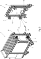
- a first embodiment of a position detector is in 1 shown.
- the position detector according to 1 comprises four fixing devices 3 and a sensor system 4 with a spring 42 and a sensor 41 arranged in the spring 42.
- the sensor system 4 is located on a first surface A of a tool carrier 1 and the fixing devices 3 are located on a second surface B of a production line 2.
- a detection object 5 is also arranged on the second surface B.
- the fixing devices 3 arranged at the corner points of the second surface B define a centroid S F in the second surface B, through which a central feed axis Z runs, along which the first surface A can be fed to the second surface B.
- Appropriate holders 31 are arranged on the tool carrier 1 to correspond to the fixing devices 3 . When the tool carrier 1 is delivered to the production line 2 , each holder 31 can be fixed to the corresponding fixing device 3 .
- One sensor 41 and one spring 42 are advantageously arranged on the central infeed axis Z, as in FIG 1 shown. This increases the accuracy of the detection of positioning and/or fixation, since essentially the same spring force F F can be exerted on all fixation devices 3 and the sensor 41 can detect an incorrect fixation on each of the fixation devices 3 in the same way. If the delivery is correct, the first surface A is fixed to the second surface B on all fixing devices 3 and is therefore correctly positioned. Correct positioning of the tool carrier 1 is ensured by the self-centering fixing devices 3.
- the sensor system 4 is designed to detect incorrect positioning and/or incorrect fixing.
- the sensor 41 is designed as a distance sensor and detects a distance to a detection object 5. If the detected distance does not correspond to a defined target value or is not within a defined target value range, the sensor 41 emits an acoustic signal and/or an optical signal.
- spring 42 is designed to exert a defined spring force F F , which can act, for example, along the central infeed axis Z, against the first Exercise surface A of the tool carrier 1 and the second surface B of the production line 2.
- the position detector is able to detect not only erroneous positioning but also erroneous fixation with just one sensor 41 .
- the spring force F F is advantageously large enough to overcome a weight force F G and static friction of the tool carrier 1 in the event of incorrect positioning or incorrect fixing.
- the magnitude of the spring force F F depends in particular on a spring constant D F of the spring 42 and a spring deflection L F or a change in the spring deflection L F of the spring 42 as a result of the tool carrier 1 being advanced.
- Exact detection of the positioning and/or the fixation is particularly necessary when at least one tool or at least one tool component is arranged on or on the tool carrier 1, which requires a high level of precision, such as a robot arm, a control device or a measuring device.
- FIG. 2A An embodiment of a spring 42 and a sensor 41 according to 1 is in Figure 2A shown.
- the spring 42 is designed as a cylindrical torsion spring with a constant coil diameter and the sensor 41 is designed as a non-contact capacitive sensor.
- the sensor 41 is arranged inside the spring 42, as a result of which it is largely protected against external mechanical influences.
- the sensor 41 forms with the detection object 5 an electrical capacitor, the distance between sensor 41 and detection object 5 determining a capacitance.
- the use of a capacitive sensor makes sense when the target value for the detected distance is smaller than a sensor diameter.
- FIG. 2B An embodiment of a detection object 5 according to 1 is in Figure 2B shown.
- the detection object 5 serves as a reference object for the sensor 41.
- the sensor 41 is designed to detect the distance to the detection object 5 and to trigger a signal when a predetermined setpoint or setpoint range is exceeded or fallen below.
- a signaling device for example a loudspeaker or a lamp, is designed to transmit the signal to a user, with which an incorrect positioning and/or fixing of the tool carrier 1 on the production line 2 is indicated.
- the sensor system 4 can comprise two springs 42 and two sensors 41, as shown in FIG 3 illustrated second embodiment.
- the presence of more than one spring 42 has the advantage that a desired distribution of the spring force F F acting on the first surface A can be specified.
- the springs 42 are advantageously arranged symmetrically around the centroid S F in order to exert a spring force F F on the first surface A and to ensure that at least a proportion of the spring force F F acts on each fixing device 3 .
- the springs 42 are particularly advantageously arranged in such a way that the same proportion of the spring force F F acts on each fixing device 3 . In the case of limited installation space, it can also be advantageous to use a plurality of springs 42 . If a high spring force F F is required in a limited installation space, it may be necessary to distribute the spring force F F over a number of springs 42 .
- the presence of more than one sensor 41 has the advantage that the accuracy of the detection of the positioning and/or the fixing can be achieved compared to arrangements with only one sensor 41.
- the sensor system 4 can comprise a spring 42 and three sensors 41, as in FIG 4 illustrated third embodiment shown.
- the sensors 41 are arranged in a regular triangle symmetrically around the centroid S F on the second surface B.
- the spring 42 is designed as a conical torsion spring and is arranged on the first surface A.
- a spring characteristic is therefore non-linear.
- a bearing surface of the spring 42 is reduced at one end of the spring, which can impair the stability and flexibility of the arrangement.
- FIG. 5 Another embodiment of a spring 42 and a sensor 41 is in figure 5 shown.
- the sensor 41 is designed as a mechanical distance sensor, which can detect a distance by mechanically touching or contacting a detection object 5 .
- the sensor 41 is designed as an optical distance sensor that can detect a distance by means of optical elements. In this case, for example, a transit time of a light can be measured in order to detect the distance. Using optical distance sensors makes sense in particular when the target value for the detected distance is large compared to the sensor diameter.
- the sensor system 4 can comprise two springs 42 and a sensor 41, as in FIG 7 shown.
- the sensor 41 is arranged between the springs 42, which are designed as leaf springs, as a result of which it is largely protected against external mechanical influences.
- the use of leaf springs is particularly useful when there is a lot of space available.
- Leaf springs are simple in terms of function and structure and are inexpensive. Depending on the design, they have a linear or non-linear spring characteristic. Leaf springs also usually have better damping properties than torsion springs.
- one of the areas A or B can also be used as the detection object 5 .
- the presence of a detection object 5 may be superfluous.
- the second surface B must be prepared accordingly.
- the second surface B can be coated with a reflective layer, for example.
- the sensor 41 can, as also in 7 shown, be designed as an inductive sensor. Using inductive distance sensors makes sense in particular when the target value for the detected distance is large compared to the sensor diameter.
Landscapes
- Physics & Mathematics (AREA)
- General Physics & Mathematics (AREA)
- Engineering & Computer Science (AREA)
- Mechanical Engineering (AREA)
- Length Measuring Devices With Unspecified Measuring Means (AREA)
- Automatic Assembly (AREA)
Applications Claiming Priority (1)
| Application Number | Priority Date | Filing Date | Title |
|---|---|---|---|
| DE102021133643.0A DE102021133643B4 (de) | 2021-12-17 | 2021-12-17 | Positionsdetektor |
Publications (1)
| Publication Number | Publication Date |
|---|---|
| EP4197704A1 true EP4197704A1 (fr) | 2023-06-21 |
Family
ID=84829844
Family Applications (1)
| Application Number | Title | Priority Date | Filing Date |
|---|---|---|---|
| EP22213108.8A Pending EP4197704A1 (fr) | 2021-12-17 | 2022-12-13 | Détecteur de position |
Country Status (2)
| Country | Link |
|---|---|
| EP (1) | EP4197704A1 (fr) |
| DE (1) | DE102021133643B4 (fr) |
Citations (9)
| Publication number | Priority date | Publication date | Assignee | Title |
|---|---|---|---|---|
| EP0259471B1 (fr) | 1986-03-10 | 1991-08-21 | Rheinmetall GmbH | Dispositif de controle et/ou de saisie des dimensions, des changements dans les dimensions, de la position et des changements dans la position de pieces a usiner, organes de reglage et similaires |
| DE10245865A1 (de) | 2002-09-30 | 2004-04-15 | Esmo Ag | Positionier- und Verriegelungsvorrichtung |
| EP1769900A2 (fr) * | 2005-09-30 | 2007-04-04 | 3D Systems, Inc. | Système de fabricage et procédé de prototypage rapide |
| EP1862767A2 (fr) | 2006-06-01 | 2007-12-05 | ELESTA relays GmbH | Capteur de position de sécurité pour cylindre, cylindre doté d'un tel capteur de position |
| DE102007017207A1 (de) * | 2006-08-17 | 2008-02-21 | Kb Knecht Gmbh | Vorrichtung zur Erfassung von Werkzeugen in einer Aufbewahrungseinrichtung |
| DE102008031372A1 (de) * | 2008-07-04 | 2010-01-07 | Gedore-Werkzeugfabrik Otto Dowidat Kg | Überwachung des Vorhandenseins eines Handwerkzeugs |
| DE102014219009A1 (de) | 2014-09-22 | 2016-03-24 | Continental Teves Ag & Co. Ohg | Positionssensor |
| WO2018063476A1 (fr) * | 2016-09-29 | 2018-04-05 | Stanley Industrial & Automotive, Llc | Système de détection d'outils à de multiples emplacements |
| WO2021062187A1 (fr) * | 2019-09-25 | 2021-04-01 | Snap-On Incorporated | Utilisation d'identifiants de contenu sur écran dans des systèmes de commande d'outils automatisés |
Family Cites Families (1)
| Publication number | Priority date | Publication date | Assignee | Title |
|---|---|---|---|---|
| DE102016202637A1 (de) | 2016-02-19 | 2017-08-24 | Micro-Epsilon Messtechnik Gmbh & Co. Kg | Sensor und Sensorelement |
-
2021
- 2021-12-17 DE DE102021133643.0A patent/DE102021133643B4/de active Active
-
2022
- 2022-12-13 EP EP22213108.8A patent/EP4197704A1/fr active Pending
Patent Citations (9)
| Publication number | Priority date | Publication date | Assignee | Title |
|---|---|---|---|---|
| EP0259471B1 (fr) | 1986-03-10 | 1991-08-21 | Rheinmetall GmbH | Dispositif de controle et/ou de saisie des dimensions, des changements dans les dimensions, de la position et des changements dans la position de pieces a usiner, organes de reglage et similaires |
| DE10245865A1 (de) | 2002-09-30 | 2004-04-15 | Esmo Ag | Positionier- und Verriegelungsvorrichtung |
| EP1769900A2 (fr) * | 2005-09-30 | 2007-04-04 | 3D Systems, Inc. | Système de fabricage et procédé de prototypage rapide |
| EP1862767A2 (fr) | 2006-06-01 | 2007-12-05 | ELESTA relays GmbH | Capteur de position de sécurité pour cylindre, cylindre doté d'un tel capteur de position |
| DE102007017207A1 (de) * | 2006-08-17 | 2008-02-21 | Kb Knecht Gmbh | Vorrichtung zur Erfassung von Werkzeugen in einer Aufbewahrungseinrichtung |
| DE102008031372A1 (de) * | 2008-07-04 | 2010-01-07 | Gedore-Werkzeugfabrik Otto Dowidat Kg | Überwachung des Vorhandenseins eines Handwerkzeugs |
| DE102014219009A1 (de) | 2014-09-22 | 2016-03-24 | Continental Teves Ag & Co. Ohg | Positionssensor |
| WO2018063476A1 (fr) * | 2016-09-29 | 2018-04-05 | Stanley Industrial & Automotive, Llc | Système de détection d'outils à de multiples emplacements |
| WO2021062187A1 (fr) * | 2019-09-25 | 2021-04-01 | Snap-On Incorporated | Utilisation d'identifiants de contenu sur écran dans des systèmes de commande d'outils automatisés |
Also Published As
| Publication number | Publication date |
|---|---|
| DE102021133643A1 (de) | 2023-06-22 |
| DE102021133643B4 (de) | 2024-01-25 |
Similar Documents
| Publication | Publication Date | Title |
|---|---|---|
| DE102007024910B4 (de) | Anordnung zur Magnetfeld-Vermessung | |
| EP2354769B1 (fr) | Capteur angulaire et procédé de détermination d'un angle entre un agencement de capteurs et un champ magnétique | |
| DE3234471C1 (de) | Mehrkoordinaten-Tastkopf | |
| DE69323289T3 (de) | Tastsonde und Signalverarbeitungsschaltung dafür | |
| DE4317285C2 (de) | Kapazitive Meßsonde für die berührungslose Abstastung von Werkstückoberflächen | |
| EP2728330B1 (fr) | Procédé et dispositif destinés à la détermination du déséquilibre statique | |
| DE102017106741B4 (de) | Oberflächenmessgerät | |
| DE102016226073A1 (de) | Vorrichtung zum einsatz in einer numerisch gesteuerten werkzeugmaschine zur verwendung in einem verfahren zum vermessen der numerisch gesteuerten werkzeugmaschine | |
| DE102011079738A1 (de) | Tastkopf | |
| DE102018002221A1 (de) | Sensoreinrichtung zum Erfassen einer Formveränderung eines Batteriekörpers einer Fahrzeugbatterie sowie Verfahren zum Erfassen einer Formveränderung eines Batteriekörpers einer Fahrzeugbatterie | |
| DE102013225463A1 (de) | Bedienvorrichtung für ein elektrisches Gerät oder eine Anlage, insbesondere für eine Fahrzeugkomponente | |
| DE102018103420A1 (de) | Messgerät zur Oberflächen- oder Konturmessung | |
| DE102021133643A1 (de) | Positionsdetektor | |
| EP1684059B1 (fr) | Dispositif pour générer et mesurer avec une haute précision des forces et des déplacements | |
| DE2553403A1 (de) | Vorrichtung zum feststellen von unebenheiten einer gekruemmten flaeche | |
| DE102013201513A1 (de) | Anordnung und Verfahren zur Positionierung eines Bearbeitungswerkzeuges gegenüber einem Werkstück | |
| DE102011104228B4 (de) | Vorrichtung zur Längenmessung und Verwendung der Vorrichtung zur Bestimmung physikalischer Eigenschaften von Messobjekten | |
| EP3309520A1 (fr) | Système de mesure d'angle destiné à déterminer un angle de rotation | |
| EP3301436B1 (fr) | Appareil de mesure de conductivité destiné à mesurer une conductivité électrique d'un milieu liquide | |
| DE102013008238A1 (de) | Vorrichtung zur Härtemessung | |
| DD220714A1 (de) | Vorrichtung zur messung der muef | |
| DE102021125445B4 (de) | Vorrichtung zur Erfassung einer Relativbewegung sowie 3D Eingabegerät | |
| AT527747B1 (de) | Batteriehalterung mit Mikrodraht-Sensoren | |
| EP3614096B1 (fr) | Système par contact | |
| DE3612338C2 (fr) |
Legal Events
| Date | Code | Title | Description |
|---|---|---|---|
| PUAI | Public reference made under article 153(3) epc to a published international application that has entered the european phase |
Free format text: ORIGINAL CODE: 0009012 |
|
| STAA | Information on the status of an ep patent application or granted ep patent |
Free format text: STATUS: THE APPLICATION HAS BEEN PUBLISHED |
|
| AK | Designated contracting states |
Kind code of ref document: A1 Designated state(s): AL AT BE BG CH CY CZ DE DK EE ES FI FR GB GR HR HU IE IS IT LI LT LU LV MC ME MK MT NL NO PL PT RO RS SE SI SK SM TR |
|
| STAA | Information on the status of an ep patent application or granted ep patent |
Free format text: STATUS: REQUEST FOR EXAMINATION WAS MADE |
|
| 17P | Request for examination filed |
Effective date: 20231221 |
|
| RBV | Designated contracting states (corrected) |
Designated state(s): AL AT BE BG CH CY CZ DE DK EE ES FI FR GB GR HR HU IE IS IT LI LT LU LV MC ME MK MT NL NO PL PT RO RS SE SI SK SM TR |