EP4197747B1 - Partie de connexion pour un processus d'assemblage industriel, connexion de partie et procédé de connexion par adhésion d'une partie de connexion et d'une partie d'accouplement - Google Patents
Partie de connexion pour un processus d'assemblage industriel, connexion de partie et procédé de connexion par adhésion d'une partie de connexion et d'une partie d'accouplement Download PDFInfo
- Publication number
- EP4197747B1 EP4197747B1 EP21214723.5A EP21214723A EP4197747B1 EP 4197747 B1 EP4197747 B1 EP 4197747B1 EP 21214723 A EP21214723 A EP 21214723A EP 4197747 B1 EP4197747 B1 EP 4197747B1
- Authority
- EP
- European Patent Office
- Prior art keywords
- connection
- connection surface
- body portion
- positioning protrusion
- securing
- Prior art date
- Legal status (The legal status is an assumption and is not a legal conclusion. Google has not performed a legal analysis and makes no representation as to the accuracy of the status listed.)
- Active
Links
Images

Classifications
-
- F—MECHANICAL ENGINEERING; LIGHTING; HEATING; WEAPONS; BLASTING
- F16—ENGINEERING ELEMENTS AND UNITS; GENERAL MEASURES FOR PRODUCING AND MAINTAINING EFFECTIVE FUNCTIONING OF MACHINES OR INSTALLATIONS; THERMAL INSULATION IN GENERAL
- F16B—DEVICES FOR FASTENING OR SECURING CONSTRUCTIONAL ELEMENTS OR MACHINE PARTS TOGETHER, e.g. NAILS, BOLTS, CIRCLIPS, CLAMPS, CLIPS OR WEDGES; JOINTS OR JOINTING
- F16B5/00—Joining sheets or plates, e.g. panels, to one another or to strips or bars parallel to them
- F16B5/08—Joining sheets or plates, e.g. panels, to one another or to strips or bars parallel to them by means of welds or the like
-
- B—PERFORMING OPERATIONS; TRANSPORTING
- B29—WORKING OF PLASTICS; WORKING OF SUBSTANCES IN A PLASTIC STATE IN GENERAL
- B29C—SHAPING OR JOINING OF PLASTICS; SHAPING OF MATERIAL IN A PLASTIC STATE, NOT OTHERWISE PROVIDED FOR; AFTER-TREATMENT OF THE SHAPED PRODUCTS, e.g. REPAIRING
- B29C65/00—Joining or sealing of preformed parts, e.g. welding of plastics materials; Apparatus therefor
- B29C65/48—Joining or sealing of preformed parts, e.g. welding of plastics materials; Apparatus therefor using adhesives, i.e. using supplementary joining material; solvent bonding
-
- F—MECHANICAL ENGINEERING; LIGHTING; HEATING; WEAPONS; BLASTING
- F16—ENGINEERING ELEMENTS AND UNITS; GENERAL MEASURES FOR PRODUCING AND MAINTAINING EFFECTIVE FUNCTIONING OF MACHINES OR INSTALLATIONS; THERMAL INSULATION IN GENERAL
- F16B—DEVICES FOR FASTENING OR SECURING CONSTRUCTIONAL ELEMENTS OR MACHINE PARTS TOGETHER, e.g. NAILS, BOLTS, CIRCLIPS, CLAMPS, CLIPS OR WEDGES; JOINTS OR JOINTING
- F16B4/00—Shrinkage connections, e.g. assembled with the parts at different temperature; Force fits; Non-releasable friction-grip fastenings
- F16B4/004—Press fits, force fits, interference fits, i.e. fits without heat or chemical treatment
-
- B—PERFORMING OPERATIONS; TRANSPORTING
- B29—WORKING OF PLASTICS; WORKING OF SUBSTANCES IN A PLASTIC STATE IN GENERAL
- B29C—SHAPING OR JOINING OF PLASTICS; SHAPING OF MATERIAL IN A PLASTIC STATE, NOT OTHERWISE PROVIDED FOR; AFTER-TREATMENT OF THE SHAPED PRODUCTS, e.g. REPAIRING
- B29C65/00—Joining or sealing of preformed parts, e.g. welding of plastics materials; Apparatus therefor
- B29C65/48—Joining or sealing of preformed parts, e.g. welding of plastics materials; Apparatus therefor using adhesives, i.e. using supplementary joining material; solvent bonding
- B29C65/50—Joining or sealing of preformed parts, e.g. welding of plastics materials; Apparatus therefor using adhesives, i.e. using supplementary joining material; solvent bonding using adhesive tape, e.g. thermoplastic tape; using threads or the like
-
- B—PERFORMING OPERATIONS; TRANSPORTING
- B29—WORKING OF PLASTICS; WORKING OF SUBSTANCES IN A PLASTIC STATE IN GENERAL
- B29C—SHAPING OR JOINING OF PLASTICS; SHAPING OF MATERIAL IN A PLASTIC STATE, NOT OTHERWISE PROVIDED FOR; AFTER-TREATMENT OF THE SHAPED PRODUCTS, e.g. REPAIRING
- B29C65/00—Joining or sealing of preformed parts, e.g. welding of plastics materials; Apparatus therefor
- B29C65/78—Means for handling the parts to be joined, e.g. for making containers or hollow articles, e.g. means for handling sheets, plates, web-like materials, tubular articles, hollow articles or elements to be joined therewith; Means for discharging the joined articles from the joining apparatus
-
- B—PERFORMING OPERATIONS; TRANSPORTING
- B29—WORKING OF PLASTICS; WORKING OF SUBSTANCES IN A PLASTIC STATE IN GENERAL
- B29C—SHAPING OR JOINING OF PLASTICS; SHAPING OF MATERIAL IN A PLASTIC STATE, NOT OTHERWISE PROVIDED FOR; AFTER-TREATMENT OF THE SHAPED PRODUCTS, e.g. REPAIRING
- B29C66/00—General aspects of processes or apparatus for joining preformed parts
- B29C66/004—Preventing sticking together, e.g. of some areas of the parts to be joined
-
- B—PERFORMING OPERATIONS; TRANSPORTING
- B29—WORKING OF PLASTICS; WORKING OF SUBSTANCES IN A PLASTIC STATE IN GENERAL
- B29C—SHAPING OR JOINING OF PLASTICS; SHAPING OF MATERIAL IN A PLASTIC STATE, NOT OTHERWISE PROVIDED FOR; AFTER-TREATMENT OF THE SHAPED PRODUCTS, e.g. REPAIRING
- B29C66/00—General aspects of processes or apparatus for joining preformed parts
- B29C66/01—General aspects dealing with the joint area or with the area to be joined
- B29C66/05—Particular design of joint configurations
- B29C66/10—Particular design of joint configurations particular design of the joint cross-sections
- B29C66/11—Joint cross-sections comprising a single joint-segment, i.e. one of the parts to be joined comprising a single joint-segment in the joint cross-section
- B29C66/112—Single lapped joints
- B29C66/1122—Single lap to lap joints, i.e. overlap joints
-
- B—PERFORMING OPERATIONS; TRANSPORTING
- B29—WORKING OF PLASTICS; WORKING OF SUBSTANCES IN A PLASTIC STATE IN GENERAL
- B29C—SHAPING OR JOINING OF PLASTICS; SHAPING OF MATERIAL IN A PLASTIC STATE, NOT OTHERWISE PROVIDED FOR; AFTER-TREATMENT OF THE SHAPED PRODUCTS, e.g. REPAIRING
- B29C66/00—General aspects of processes or apparatus for joining preformed parts
- B29C66/40—General aspects of joining substantially flat articles, e.g. plates, sheets or web-like materials; Making flat seams in tubular or hollow articles; Joining single elements to substantially flat surfaces
- B29C66/47—Joining single elements to sheets, plates or other substantially flat surfaces
- B29C66/474—Joining single elements to sheets, plates or other substantially flat surfaces said single elements being substantially non-flat
-
- B—PERFORMING OPERATIONS; TRANSPORTING
- B29—WORKING OF PLASTICS; WORKING OF SUBSTANCES IN A PLASTIC STATE IN GENERAL
- B29C—SHAPING OR JOINING OF PLASTICS; SHAPING OF MATERIAL IN A PLASTIC STATE, NOT OTHERWISE PROVIDED FOR; AFTER-TREATMENT OF THE SHAPED PRODUCTS, e.g. REPAIRING
- B29C66/00—General aspects of processes or apparatus for joining preformed parts
- B29C66/50—General aspects of joining tubular articles; General aspects of joining long products, i.e. bars or profiled elements; General aspects of joining single elements to tubular articles, hollow articles or bars; General aspects of joining several hollow-preforms to form hollow or tubular articles
- B29C66/51—Joining tubular articles, profiled elements or bars; Joining single elements to tubular articles, hollow articles or bars; Joining several hollow-preforms to form hollow or tubular articles
- B29C66/54—Joining several hollow-preforms, e.g. half-shells, to form hollow articles, e.g. for making balls, containers; Joining several hollow-preforms, e.g. half-cylinders, to form tubular articles
-
- F—MECHANICAL ENGINEERING; LIGHTING; HEATING; WEAPONS; BLASTING
- F16—ENGINEERING ELEMENTS AND UNITS; GENERAL MEASURES FOR PRODUCING AND MAINTAINING EFFECTIVE FUNCTIONING OF MACHINES OR INSTALLATIONS; THERMAL INSULATION IN GENERAL
- F16B—DEVICES FOR FASTENING OR SECURING CONSTRUCTIONAL ELEMENTS OR MACHINE PARTS TOGETHER, e.g. NAILS, BOLTS, CIRCLIPS, CLAMPS, CLIPS OR WEDGES; JOINTS OR JOINTING
- F16B11/00—Connecting constructional elements or machine parts by sticking or pressing them together, e.g. cold pressure welding
- F16B11/006—Connecting constructional elements or machine parts by sticking or pressing them together, e.g. cold pressure welding by gluing
-
- B—PERFORMING OPERATIONS; TRANSPORTING
- B29—WORKING OF PLASTICS; WORKING OF SUBSTANCES IN A PLASTIC STATE IN GENERAL
- B29C—SHAPING OR JOINING OF PLASTICS; SHAPING OF MATERIAL IN A PLASTIC STATE, NOT OTHERWISE PROVIDED FOR; AFTER-TREATMENT OF THE SHAPED PRODUCTS, e.g. REPAIRING
- B29C65/00—Joining or sealing of preformed parts, e.g. welding of plastics materials; Apparatus therefor
- B29C65/56—Joining or sealing of preformed parts, e.g. welding of plastics materials; Apparatus therefor using mechanical means or mechanical connections, e.g. form-fits
- B29C65/58—Snap connection
Definitions
- the present disclosure relates to a connection part for an industrial assembly process.
- connection part comprising such a connection part and a mating part.
- connection part and a mating part.
- connection parts connection parts, mating parts and methods for adhesively connecting a connection part and a mating part are omnipresent in industrial assembly processes, e.g. in the automotive sector.
- Adhesive connections for example adhesive connections comprising an adhesive tape, are often used since such connections can be established in a simple manner without the need of specific tools.
- connection part and the mating part are in the desired relative position upon the first contact between these parts. This is due to the fact that adhesive connections, especially adhesive connections comprising an adhesive tape, usually are established upon this first contact. Normally, it is not possible to further align the connection part and the mating part once the connection is established. Consequently, when manually establishing such an adhesive connection, a high degree of attention and concentration is necessary. When automatically establishing such an adhesive connection, elaborate and precise control methods have to be used.
- connection part according to the preamble of claim 1 is for example known from US 2006/0021242 A1 .
- connection part for an industrial assembly process.
- the connection part has a body portion and a connection surface being arranged on the body portion.
- the connection surface is configured for being connected to a mating part.
- the connection part further comprises at least one positioning protrusion being located at a distance away from an edge of the connection surface and being movably connected to the body portion.
- the at least one positioning protrusion is leg-shaped, one end portion thereof being connected to the body portion. In a pre-assembly position the positioning protrusion at least partially protrudes with respect to the connection surface, and in an assembly position the positioning protrusion is flush with the connection surface or is retracted with respect to the connection surface.
- a movable connection between the body portion and the positioning protrusion may for example be realized by a connection allowing the positioning protrusion to pivot or to slide with respect to the body portion.
- the movable connection may thus comprise a joint and/or a linear guide.
- one end of the leg-shaped positioning protrusion is connected to the body portion, the positioning protrusion is reliably connected to the body portion and movable at the same time.
- the connection surface may have any form.
- the connection surface is flat or curved. The fact that the positioning protrusion is arranged at a distance away from an edge of the connection surface means that the positioning protrusion is not configured for connecting the connection part to the mating part.
- connection part may be connected to the mating part in a simple and exact manner since in the pre-assembly position of the positioning protrusion, the positioning protrusion prevents an undesired contact between the connection part and the mating part.
- the positioning protrusion keeps the connection surface of the connection part at a predefined distance from the mating part. This facilitates the positioning of the connection part relative to the mating part.
- the positioning protrusion is retracted such that a connection may be established via the connection surface of the connection part. The positioning protrusion does not hinder this connection and does not have any negative influences thereon.
- the industrial assembly process may be an automotive assembly process.
- connection surface may be positioned at a base surface of the body portion.
- the connection surface may extend along a length of the base surface.
- connection surface may extend along a width of the base surface. It is also possible that the connection surface extends along a width and/or a length of an intermediate portion of the base surface. Such connection surfaces allow for stable and reliable connections.
- connection surface is formed by an adhesive layer being arranged on the body portion.
- an adhesive layer is suitable for providing a stable and precise connection.
- the adhesive layer comprises an adhesive tape. This is a simple and reliable manner for providing an adhesive layer.
- the at least one positioning protrusion is movably connected to the body portion via an elastically deformable section of the body portion and/or an elastically deformable section of the positioning protrusion.
- Such a connection can be produced at comparatively low costs.
- the movability can be adjusted depending on the specific application.
- the leg-shaped positioning protrusion may substantially extend in parallel to the connection surface.
- the end portion of the positioning protrusion not being connected to the body portion may protrude over the connection surface in the pre-assembly position.
- the leg-shaped positioning protrusion may be at least partially elastically deformable.
- At least two positioning protrusion may be provided on the body portion of the connection part.
- the positioning protrusions may be positioned on opposing sides of the connection surface. Consequently, undesired contacts between the connection surface of the connection part and the mating part are avoided with enhanced reliability.
- the at least two positioning protrusions may be designated a first positioning protrusion and a second positioning protrusion.
- connection part may assume a statically well-defined state when being in the pre-assembly position and contacting a mating part.
- connection surface is kept at a predefined distance from the mating part.
- more positioning protrusions can be provided.
- connection part comprises a securing means.
- the at least one positioning protrusion is secured on the body portion by the securing means.
- the positioning protrusion is thus held in the assembly position. Consequently, it is not able to return to the pre-assembly position once it has reached the assembly position.
- This also means that the positioning protrusion does not influence a connection between the connection surface and a mating part. Such a connection is reliable and stable.
- the securing means comprises a securing protrusion and a corresponding securing depression for each of the positioning protrusions.
- the securing protrusion engages the securing depression and in the pre-assembly position the securing protrusion and the securing depression are disengaged.
- a securing means is simple in design and reliable in operation.
- the securing protrusion may be pushed into engagement with the corresponding securing depression when pressing the connection surface against a corresponding surface of the mating part for establishing a connection.
- the securing protrusion and the corresponding securing depression are shaped such that the securing protrusion is not able to leave the securing depression.
- the securing means may comprise a snap-on mechanism or an interference fit mechanism. Consequently, the positioning protrusion may be reliably secured on the body portion.
- the securing means may be configured for producing a sound when reaching the state in which the at least one positioning protrusion is secured on the body portion.
- This sound may be a click sound or a clack sound. Consequently, a user can be sure that the positioning protrusion is secured on the body portion without having to visually verify this fact.
- the securing means comprises a securing protrusion and a securing depression
- the sound may be produced by the securing protrusion entering the securing depression.
- the securing means is configured such that the state in which the at least one positioning protrusion is secured on the body portion is reached by applying a force equaling, exceeding or being smaller than a predefined mounting force. If the force equals the mounting force or is smaller than the mounting force, the positioning protrusion may be transferred into the secured position by simply mounting the connection part on the mating part. No additional force or effort is necessary. If the force exceeds the mounting force, the force for bringing the positioning protrusion into the secured state creates a predefined resistance when mounting the connection part to the mating part. This prevents undesired connections.
- the force being necessary for moving the securing protrusion into the securing depression may be adjusted by choosing an appropriate geometry of the securing protrusion and the securing depression and/or by choosing appropriate materials.
- the body portion and the positioning protrusion are formed as an integral structure. Thus, no assembly is necessary.
- the body portion and the positioning protrusions may also be produced as an integral structure, e.g. by injection molding, casting or by a generative manufacturing process.
- a part connection comprising a connection part according to the present disclosure and a mating part.
- the mating part has a mating part body with a counter-connection surface.
- the connection part and the mating part are connected via the connection surface and the counter-connection surface.
- an adhesive layer e.g. in the form of an adhesive tape, may be provided on at least one of the connection surface and the counter-connection surface.
- connection part has a body portion, a connection surface being arranged on the body portion, and at least one positioning protrusion being located at a distance away from an edge of the connection surface and being movably connected to the body portion.
- the at least one positioning protrusion is leg-shaped, wherein one end portion thereof is connected to the body portion.
- the mating part has a mating part body with a counter-connection surface.
- an adhesive layer e.g. in the form of an adhesive tape, may be provided on at least one of the connection surface and the counter-connection surface.
- the method comprises sliding the at least one positioning protrusion on the mating part body and bringing the connection surface and the counter-connection surface in a desired relative position while the connection surface and the counter-connection surface are arranged within the predefined distance.
- the positioning protrusion may be used as a sliding block. As before, undesired contacts between the connection surface and the counter-connection surface are avoided.
- pressing the connection part and the mating part towards one another comprises applying a mounting force to at least one of the connection part and the mating part.
- the mounting force is oriented non-parallel to the connection surface. It is obvious that the mounting force it applied to one of the parts and that a corresponding counter-force needs to be applied to the respective other part.
- the mounting force may be oriented perpendicular to at least one of the connection surface and the counter-connection surface. The mounting force is to be understood as the force necessary for establishing the connection between the connection part and the mating part.
- connection part and the part connection may be combined with features described above with regard to the method.
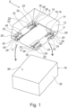
- Figure 1 shows a connection part 10.
- connection part 10 comprises a body portion 12.
- connection surface 14 is arranged on the body portion 12.
- connection surface 14 is formed by an adhesive layer 16 being arranged on the body portion 12.
- the adhesive layer 16 comprises an adhesive tape 18.
- connection part 10 further comprises four positioning protrusions 20.
- the positioning protrusions 20 are located at a distance d away from an edge of the connection surface 14 respectively. Put otherwise, the positioning protrusions 20 are located outside the connection surface 14.
- the positioning protrusions 20 are leg-shaped.
- the positioning protrusions 20 substantially extend parallel to the connection surface 14.
- a first end portion 22 of each of the positioning protrusions 20 is connected to the body portion 12.
- each of the positioning protrusions 20 comprises an elastically deformable section 24.
- the positioning protrusions 20 are movably connected to the body portion 12 via these sections 24.
- the positioning protrusions 20 and the body portion 12 are formed as an integral structure. More precisely, the connection part 10 is an injection molded part made from plastics material. Thus, the body portion 12 and the positioning protrusions 20 are formed together in a single injection molding process.
- the positioning protrusions 20 are shown in a pre-assembly position. In this position, the positioning protrusions 20 at least partially protrude with respect to the connection surface 14.
- each positioning protrusion 20 being arranged opposite the respective first end portion 22 protrude over the connecting surface 14.
- the positioning protrusions 20 Due to the movability of the positioning protrusions 20, they can also assume an assembly position wherein the positioning protrusions 20 are flush with the connection surface 14 or are retracted with respect to the connection surface 14.
- connection part 10 also comprises a securing means 28.
- a securing means 28 is provided for each of the positioning protrusions 20.
- each securing means 28 comprises a securing protrusion 30 being located on the corresponding positioning protrusion 20 and a securing depression 32 being located on the body portion 12.
- the securing means 28 is configured for securing the corresponding positioning protrusion 20 in the assembly position.
- each of the securing protrusions 30 engages the corresponding securing depression 32.
- the securing means 28 are configured such that the state in which the corresponding positioning protrusion 20 is secured on the body portion 12 may be reached by applying a force equaling a predefined mounting force. This means that the positioning protrusions 20 will be moved into the assembly position when the connecting part 10 is mounted to a mating part as will be explained further below.
- This force is used for moving the securing protrusions 30 into the corresponding securing depressions 32, thereby also elastically deforming the elastically deformable sections 24.
- the securing means 28 is configured for producing a sound when the securing protrusion 30 reaches the corresponding securing depression.
- connection part 10 is configured for being connected to a mating part 34 via the connection surface 14.
- the mating part 34 has a mating part body 36.
- a counter-connection surface 38 is provided on the mating part body 36 .
- connection part 10 and the mating part 34 are configured for being connected via the connection surface 14 and the counter-connection surface 38.
- connection part 10 and the mating part 34 form a part connection 40.
- connection part 10 is connected to connection part 10 and the mating part 34 .
- a part connection 40 is produced.
- Figure 2 shows a situation corresponding to Figure 1 , wherein the connection part 10 and the mating part 34 do not at all contact each other.
- a first step of the method is illustrated in Figure 3 .
- the first step comprises bringing the positioning protrusions 20 in contact with the mating part body 36.
- the positioning protrusions 20 are in the pre-assembly position, i.e. they protrude with respect to the connection surface 14.
- connection surface 14 and the counter-connection surface 38 are arranged within a predefined distance D.
- the positioning protrusions 20 may slide on the mating part body 36 in order to bring the connection surface 14 and the counter-connection surface 38 in a desired relative position.
- connection surface 14 and the counter-connection surface 38 are arranged within the predefined distance D.
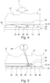
- connection part 10 Thereafter, a mounting force F is applied to the connection part 10.
- the mounting force F is directed towards the mating part 34 (cf. Figure 4 ).
- the mounting force F is oriented perpendicular to the connection surface 14 and the counter-connection surface 38.
- connection part 10 and the mating part 34 are pressed towards one another.
- the elastically deformable sections 24 of the positioning protrusion 20 are deformed elastically such that the positioning protrusions 20 are bent towards the body portion 12 of the connection part 10.
- connection surface 14 and the counter-connection surface 38 contact each other (cf. Figure 5 ).
- the positioning protrusions 20 reach the assembly position in which they are retracted with respect to the connection surface 14.
- each of the securing protrusions 30 engages the corresponding securing depression 32. This means that the positioning protrusions 20 are secured in the assembly position.
- the securing protrusions 30 produce a sound 46 when engaging the corresponding securing depression 32.
- connection part 10 and the mating part 34 is purely illustrative.
- the connection part 10 and the mating part 34 can have any form as long as the connecting surface 14 and the counter-connection surface 38 are suitable for contacting each other.
- connection part 10 and/or the mating part 34 are formed as portions of a respective bigger part.
Landscapes
- Engineering & Computer Science (AREA)
- Mechanical Engineering (AREA)
- General Engineering & Computer Science (AREA)
- Connection Of Plates (AREA)
- Standing Axle, Rod, Or Tube Structures Coupled By Welding, Adhesion, Or Deposition (AREA)
Claims (14)
- Pièce de liaison (10) pour un processus d'assemblage industriel, la partie de liaison (10) comportant une partie corps (12) et une surface de liaison (14) disposée sur la partie corps (12), la surface de liaison (14) étant configurée pour être reliée à une partie d'accouplement (34), et au moins une protubérance de positionnement (20) étant situé à une distance (d) d'un bord de la surface de liaison (14) et étant reliée de manière mobile à la partie corps (12), dans laquelle, dans une position de préassemblage, la protubérance de positionnement (20) fait au moins partiellement saillie par rapport à la surface de liaison (14), et dans une position de montage, la protubérance de positionnement (20) affleure la surface de liaison (14) ou est rétractée par rapport à la surface de liaison (14),
caractérisée en ce que la au moins une protubérance de positionnement (20) est en forme de patte, une partie d'extrémité (22) de celle-ci étant reliée à la partie corps (12) . - Pièce de liaison (10) selon la revendication 1, dans laquelle la surface de liaison (14) est formée par une couche adhésive (16) disposée sur la partie corps (12).
- Pièce de liaison (10) selon la revendication 2, dans laquelle la couche adhésive (16) comprend un ruban adhésif (18) .
- Pièce de liaison (10) selon l'une quelconque des revendications précédentes, dans laquelle la au moins une protubérance de positionnement (20) est reliée de manière mobile à la partie corps (12) par l'intermédiaire d'une section élastiquement déformable de la partie corps (12) et/ou une section élastiquement déformable (24) de la protubérance de positionnement (20).
- Pièce de liaison (10) selon l'une quelconque des revendications précédentes, dans laquelle au moins deux protubérances de positionnement (20) sont prévues sur la partie corps (12).
- Pièce de liaison (10) selon l'une quelconque des revendications précédentes, comprenant un moyen de fixation (28), dans laquelle, dans la position d'assemblage, la au moins une protubérance de positionnement (20) est fixée sur la partie corps (12) par le moyen de fixation (28).
- Pièce de liaison (10) selon la revendication 6, dans laquelle le moyen de fixation (28) comprend une protubérance de fixation (30) et un creux de fixation correspondant (32) pour chacune des protubérances de positionnement (20), dans laquelle, dans la position d'assemblage, la protubérance de fixation (30) vient en prise avec le creux de fixation (32) et, dans la position de préassemblage, la protubérance de fixation (30) et le creux de fixation (32) sont désaccouplés.
- Pièce de liaison (10) selon la revendication 6 ou la revendication 7, dans laquelle le moyen de fixation (28) est configuré pour produire un son (46) lorsqu'il atteint l'état dans lequel au moins une protubérance de positionnement (20) est fixée sur la partie corps (12).
- Pièce de liaison (10) selon l'une quelconque des revendications 6 à 8, dans laquelle le moyen de fixation (28) est configuré de telle sorte que l'état dans lequel la au moins une protubérance de positionnement (20) est fixée sur la partie corps (12) est atteint en appliquant une force égale, supérieure ou inférieure à une force de montage prédéfinie (F).
- Pièce de liaison (10) selon l'une quelconque des revendications précédentes, dans laquelle la partie corps (12) et la protubérance de positionnement (20) sont formées en tant que structure monobloc.
- Liaison de pièces (40) comprenant une pièce de liaison (10) selon l'une quelconque des revendications précédentes et une pièce d'accouplement (34) ayant un corps de pièce d'accouplement (36) avec une surface de contre-liaison (38), dans laquelle la pièce de liaison (10) et la pièce d'accouplement (34) sont reliées par l'intermédiaire de la surface de liaison (14) et de la surface de contre-liaison (38) .
- Procédé de liaison adhésive d'une pièce de liaison (10) et d'une pièce d'accouplement (34), la pièce de liaison (10) comportant une partie corps (12), une surface de liaison (14) étant disposée sur la partie corps (12), et au au moins une protubérance de positionnement (20) étant située à une distance (d) d'un bord de la surface de liaison (14), étant reliée de manière mobile à la partie corps (12), et étant en forme de patte, dans lequel une partie d'extrémité (22) de celle-ci est reliée à la partie corps (12), et
la pièce d'accouplement (34) ayant un corps de pièce d'accouplement (36) avec une surface de contre-liaison (38), le procédé comprenant :- le fait d'amener la au moins une protubérance de positionnement (20) en contact avec le corps de pièce d'accouplement (36), la au moins une protubérance de positionnement (20) faisant au moins partiellement saillie par rapport à la surface de liaison (14) de telle sorte que la surface de liaison (14) et la surface de contre-liaison (38) sont disposées à une distance prédéfinie (D) l'une de l'autre,- le pressage de la partie de liaison (10) et de la partie d'accouplement (34) l'une vers l'autre jusqu'à ce que la surface de liaison (14) et la surface de contre-liaison (38) soient en contact l'une avec l'autre et de telle sorte que la au moins une protubérance de positionnement (20) soit déplacée vers une position dans laquelle elle affleure la surface de liaison (14) ou est rétractée par rapport à la surface de liaison (14). - Procédé selon la revendication 12, comprenant : le fait de faire glisser la au moins une protubérance de positionnement (20) sur le corps de pièce d'accouplement (36) et d'amener la surface de liaison (14) et la surface de contre-liaison (38) dans une position relative souhaitée tandis que la surface de liaison (14) et la surface de contre-liaison (38) sont disposées à la distance prédéfinie (D) .
- Procédé selon la revendication 12 ou 13, dans lequel le pressage de la partie de liaison (10) et de la partie d'accouplement (34) l'une vers l'autre comprend l'application d'une force de montage (F) à au moins l'une parmi la partie de liaison (10) et la partie d'accouplement (34), la force de montage (F) étant orientée de manière non parallèle à la surface de liaison (14).
Priority Applications (3)
| Application Number | Priority Date | Filing Date | Title |
|---|---|---|---|
| EP21214723.5A EP4197747B1 (fr) | 2021-12-15 | 2021-12-15 | Partie de connexion pour un processus d'assemblage industriel, connexion de partie et procédé de connexion par adhésion d'une partie de connexion et d'une partie d'accouplement |
| CN202211596981.1A CN116263177A (zh) | 2021-12-15 | 2022-12-12 | 工业组装过程的连接部件、连接部件和配合部件的部件连接件及其粘合连接方法 |
| US18/080,083 US20230184277A1 (en) | 2021-12-15 | 2022-12-13 | Connection part for an industrial assembly process, part connection and method for adhesively connecting a connection part and a mating part |
Applications Claiming Priority (1)
| Application Number | Priority Date | Filing Date | Title |
|---|---|---|---|
| EP21214723.5A EP4197747B1 (fr) | 2021-12-15 | 2021-12-15 | Partie de connexion pour un processus d'assemblage industriel, connexion de partie et procédé de connexion par adhésion d'une partie de connexion et d'une partie d'accouplement |
Publications (2)
| Publication Number | Publication Date |
|---|---|
| EP4197747A1 EP4197747A1 (fr) | 2023-06-21 |
| EP4197747B1 true EP4197747B1 (fr) | 2024-03-13 |
Family
ID=78916775
Family Applications (1)
| Application Number | Title | Priority Date | Filing Date |
|---|---|---|---|
| EP21214723.5A Active EP4197747B1 (fr) | 2021-12-15 | 2021-12-15 | Partie de connexion pour un processus d'assemblage industriel, connexion de partie et procédé de connexion par adhésion d'une partie de connexion et d'une partie d'accouplement |
Country Status (3)
| Country | Link |
|---|---|
| US (1) | US20230184277A1 (fr) |
| EP (1) | EP4197747B1 (fr) |
| CN (1) | CN116263177A (fr) |
Family Cites Families (7)
| Publication number | Priority date | Publication date | Assignee | Title |
|---|---|---|---|---|
| US4421288A (en) * | 1981-01-19 | 1983-12-20 | Henry Blaszkowski | Suction cup |
| US5593120A (en) * | 1994-11-21 | 1997-01-14 | Minnesota Mining And Manufacturing Company | Quick-mounting fastening assembly |
| CA2181865C (fr) * | 1995-07-28 | 2003-04-29 | Charles G. Hutter, Iii | Plaque filetee encollee comportant une gaine de revetement integree |
| AU2002950303A0 (en) * | 2002-07-22 | 2002-09-12 | Telezygology Inc. | Improvements in assembly and disassembly |
| EP1621847B1 (fr) * | 2004-07-23 | 2013-07-17 | Dr. Johannes Heidenhain GmbH | Elément, en particulier capteur, et procédé pour coller ledit élément |
| JP4938345B2 (ja) * | 2006-04-24 | 2012-05-23 | 株式会社パイオラックス | 部品の取付構造 |
| KR101063058B1 (ko) * | 2010-10-28 | 2011-09-07 | 박민식 | 거치 대 용 기밀 부착 패드 |
-
2021
- 2021-12-15 EP EP21214723.5A patent/EP4197747B1/fr active Active
-
2022
- 2022-12-12 CN CN202211596981.1A patent/CN116263177A/zh active Pending
- 2022-12-13 US US18/080,083 patent/US20230184277A1/en not_active Abandoned
Also Published As
| Publication number | Publication date |
|---|---|
| US20230184277A1 (en) | 2023-06-15 |
| CN116263177A (zh) | 2023-06-16 |
| EP4197747A1 (fr) | 2023-06-21 |
Similar Documents
| Publication | Publication Date | Title |
|---|---|---|
| US20180310421A1 (en) | Bracket and assembly structure for bracket | |
| CN100509487C (zh) | 模制件连接结构、模制件连接夹及模制件 | |
| CN111231598A (zh) | 稳定器装置及稳定器装置的制造方法 | |
| EP3675289B1 (fr) | Connecteur | |
| US20070247827A1 (en) | Board-mounting device | |
| EP4197747B1 (fr) | Partie de connexion pour un processus d'assemblage industriel, connexion de partie et procédé de connexion par adhésion d'une partie de connexion et d'une partie d'accouplement | |
| JP5368293B2 (ja) | 基台付き基板の製造方法 | |
| CN114060375A (zh) | 扣件及含有该扣件的壳体装置 | |
| KR20050008537A (ko) | 인코더 시스템 및 인코더 시스템 조립 방법 | |
| CN118163372A (zh) | 用于定位和连接由增材制造实现的零件段的系统和方法 | |
| JPH0512074Y2 (fr) | ||
| JP2014013930A (ja) | 基台付き基板の製造方法 | |
| CN110030240B (zh) | 定位和止动销 | |
| CN117922708A (zh) | 振动焊接成形品 | |
| US12523285B2 (en) | Wiper motor, method for assembling a wiper motor, and assembly tool | |
| CN219550793U (zh) | 卡扣结构、面框组件和空调器 | |
| CN220947859U (zh) | 一种安装结构及车辆 | |
| CN113314878A (zh) | 插针连接器 | |
| JPH0532042U (ja) | モールジヨイントクリツプ | |
| JP5122382B2 (ja) | 金属部品の電子部品本体への取付方法 | |
| JP2003123881A (ja) | 平型柔軟ケーブル用電気コネクタ | |
| CN218557296U (zh) | 汽车装饰膜的热冲切机构 | |
| CN223001483U (zh) | 分体拼接结构 | |
| CA2436062A1 (fr) | Agrafe de fixation | |
| US11739777B2 (en) | Alignment feature for an elastic averaging alignment system |
Legal Events
| Date | Code | Title | Description |
|---|---|---|---|
| PUAI | Public reference made under article 153(3) epc to a published international application that has entered the european phase |
Free format text: ORIGINAL CODE: 0009012 |
|
| STAA | Information on the status of an ep patent application or granted ep patent |
Free format text: STATUS: REQUEST FOR EXAMINATION WAS MADE |
|
| 17P | Request for examination filed |
Effective date: 20220908 |
|
| AK | Designated contracting states |
Kind code of ref document: A1 Designated state(s): AL AT BE BG CH CY CZ DE DK EE ES FI FR GB GR HR HU IE IS IT LI LT LU LV MC MK MT NL NO PL PT RO RS SE SI SK SM TR |
|
| RIC1 | Information provided on ipc code assigned before grant |
Ipc: B29C 65/50 20060101ALN20230628BHEP Ipc: B29C 65/58 20060101ALN20230628BHEP Ipc: B29C 65/48 20060101ALN20230628BHEP Ipc: F16B 11/00 20060101ALI20230628BHEP Ipc: B29C 65/00 20060101AFI20230628BHEP |
|
| RIC1 | Information provided on ipc code assigned before grant |
Ipc: B29C 65/50 20060101ALN20230725BHEP Ipc: B29C 65/58 20060101ALN20230725BHEP Ipc: B29C 65/48 20060101ALN20230725BHEP Ipc: F16B 11/00 20060101ALI20230725BHEP Ipc: B29C 65/00 20060101AFI20230725BHEP |
|
| RIC1 | Information provided on ipc code assigned before grant |
Ipc: B29C 65/50 20060101ALN20230813BHEP Ipc: B29C 65/58 20060101ALN20230813BHEP Ipc: B29C 65/48 20060101ALN20230813BHEP Ipc: B29C 65/78 20060101ALI20230813BHEP Ipc: F16B 11/00 20060101ALI20230813BHEP Ipc: B29C 65/00 20060101AFI20230813BHEP |
|
| GRAP | Despatch of communication of intention to grant a patent |
Free format text: ORIGINAL CODE: EPIDOSNIGR1 |
|
| STAA | Information on the status of an ep patent application or granted ep patent |
Free format text: STATUS: GRANT OF PATENT IS INTENDED |
|
| INTG | Intention to grant announced |
Effective date: 20230922 |
|
| GRAS | Grant fee paid |
Free format text: ORIGINAL CODE: EPIDOSNIGR3 |
|
| GRAA | (expected) grant |
Free format text: ORIGINAL CODE: 0009210 |
|
| STAA | Information on the status of an ep patent application or granted ep patent |
Free format text: STATUS: THE PATENT HAS BEEN GRANTED |
|
| AK | Designated contracting states |
Kind code of ref document: B1 Designated state(s): AL AT BE BG CH CY CZ DE DK EE ES FI FR GB GR HR HU IE IS IT LI LT LU LV MC MK MT NL NO PL PT RO RS SE SI SK SM TR |
|
| REG | Reference to a national code |
Ref country code: GB Ref legal event code: FG4D |
|
| REG | Reference to a national code |
Ref country code: CH Ref legal event code: EP |
|
| P01 | Opt-out of the competence of the unified patent court (upc) registered |
Effective date: 20240219 |
|
| REG | Reference to a national code |
Ref country code: DE Ref legal event code: R096 Ref document number: 602021010371 Country of ref document: DE |
|
| REG | Reference to a national code |
Ref country code: IE Ref legal event code: FG4D |
|
| PG25 | Lapsed in a contracting state [announced via postgrant information from national office to epo] |
Ref country code: LT Free format text: LAPSE BECAUSE OF FAILURE TO SUBMIT A TRANSLATION OF THE DESCRIPTION OR TO PAY THE FEE WITHIN THE PRESCRIBED TIME-LIMIT Effective date: 20240313 |
|
| REG | Reference to a national code |
Ref country code: LT Ref legal event code: MG9D |
|
| PG25 | Lapsed in a contracting state [announced via postgrant information from national office to epo] |
Ref country code: GR Free format text: LAPSE BECAUSE OF FAILURE TO SUBMIT A TRANSLATION OF THE DESCRIPTION OR TO PAY THE FEE WITHIN THE PRESCRIBED TIME-LIMIT Effective date: 20240614 |
|
| REG | Reference to a national code |
Ref country code: NL Ref legal event code: MP Effective date: 20240313 |
|
| PG25 | Lapsed in a contracting state [announced via postgrant information from national office to epo] |
Ref country code: RS Free format text: LAPSE BECAUSE OF FAILURE TO SUBMIT A TRANSLATION OF THE DESCRIPTION OR TO PAY THE FEE WITHIN THE PRESCRIBED TIME-LIMIT Effective date: 20240613 Ref country code: HR Free format text: LAPSE BECAUSE OF FAILURE TO SUBMIT A TRANSLATION OF THE DESCRIPTION OR TO PAY THE FEE WITHIN THE PRESCRIBED TIME-LIMIT Effective date: 20240313 |
|
| PG25 | Lapsed in a contracting state [announced via postgrant information from national office to epo] |
Ref country code: ES Free format text: LAPSE BECAUSE OF FAILURE TO SUBMIT A TRANSLATION OF THE DESCRIPTION OR TO PAY THE FEE WITHIN THE PRESCRIBED TIME-LIMIT Effective date: 20240313 |
|
| PG25 | Lapsed in a contracting state [announced via postgrant information from national office to epo] |
Ref country code: RS Free format text: LAPSE BECAUSE OF FAILURE TO SUBMIT A TRANSLATION OF THE DESCRIPTION OR TO PAY THE FEE WITHIN THE PRESCRIBED TIME-LIMIT Effective date: 20240613 Ref country code: NO Free format text: LAPSE BECAUSE OF FAILURE TO SUBMIT A TRANSLATION OF THE DESCRIPTION OR TO PAY THE FEE WITHIN THE PRESCRIBED TIME-LIMIT Effective date: 20240613 Ref country code: LT Free format text: LAPSE BECAUSE OF FAILURE TO SUBMIT A TRANSLATION OF THE DESCRIPTION OR TO PAY THE FEE WITHIN THE PRESCRIBED TIME-LIMIT Effective date: 20240313 Ref country code: HR Free format text: LAPSE BECAUSE OF FAILURE TO SUBMIT A TRANSLATION OF THE DESCRIPTION OR TO PAY THE FEE WITHIN THE PRESCRIBED TIME-LIMIT Effective date: 20240313 Ref country code: GR Free format text: LAPSE BECAUSE OF FAILURE TO SUBMIT A TRANSLATION OF THE DESCRIPTION OR TO PAY THE FEE WITHIN THE PRESCRIBED TIME-LIMIT Effective date: 20240614 Ref country code: FI Free format text: LAPSE BECAUSE OF FAILURE TO SUBMIT A TRANSLATION OF THE DESCRIPTION OR TO PAY THE FEE WITHIN THE PRESCRIBED TIME-LIMIT Effective date: 20240313 Ref country code: ES Free format text: LAPSE BECAUSE OF FAILURE TO SUBMIT A TRANSLATION OF THE DESCRIPTION OR TO PAY THE FEE WITHIN THE PRESCRIBED TIME-LIMIT Effective date: 20240313 Ref country code: BG Free format text: LAPSE BECAUSE OF FAILURE TO SUBMIT A TRANSLATION OF THE DESCRIPTION OR TO PAY THE FEE WITHIN THE PRESCRIBED TIME-LIMIT Effective date: 20240313 |
|
| REG | Reference to a national code |
Ref country code: AT Ref legal event code: MK05 Ref document number: 1665358 Country of ref document: AT Kind code of ref document: T Effective date: 20240313 |
|
| PG25 | Lapsed in a contracting state [announced via postgrant information from national office to epo] |
Ref country code: SE Free format text: LAPSE BECAUSE OF FAILURE TO SUBMIT A TRANSLATION OF THE DESCRIPTION OR TO PAY THE FEE WITHIN THE PRESCRIBED TIME-LIMIT Effective date: 20240313 Ref country code: LV Free format text: LAPSE BECAUSE OF FAILURE TO SUBMIT A TRANSLATION OF THE DESCRIPTION OR TO PAY THE FEE WITHIN THE PRESCRIBED TIME-LIMIT Effective date: 20240313 |
|
| PG25 | Lapsed in a contracting state [announced via postgrant information from national office to epo] |
Ref country code: NL Free format text: LAPSE BECAUSE OF FAILURE TO SUBMIT A TRANSLATION OF THE DESCRIPTION OR TO PAY THE FEE WITHIN THE PRESCRIBED TIME-LIMIT Effective date: 20240313 |
|
| PG25 | Lapsed in a contracting state [announced via postgrant information from national office to epo] |
Ref country code: NL Free format text: LAPSE BECAUSE OF FAILURE TO SUBMIT A TRANSLATION OF THE DESCRIPTION OR TO PAY THE FEE WITHIN THE PRESCRIBED TIME-LIMIT Effective date: 20240313 |
|
| PG25 | Lapsed in a contracting state [announced via postgrant information from national office to epo] |
Ref country code: IS Free format text: LAPSE BECAUSE OF FAILURE TO SUBMIT A TRANSLATION OF THE DESCRIPTION OR TO PAY THE FEE WITHIN THE PRESCRIBED TIME-LIMIT Effective date: 20240713 |
|
| PG25 | Lapsed in a contracting state [announced via postgrant information from national office to epo] |
Ref country code: PT Free format text: LAPSE BECAUSE OF FAILURE TO SUBMIT A TRANSLATION OF THE DESCRIPTION OR TO PAY THE FEE WITHIN THE PRESCRIBED TIME-LIMIT Effective date: 20240715 Ref country code: SM Free format text: LAPSE BECAUSE OF FAILURE TO SUBMIT A TRANSLATION OF THE DESCRIPTION OR TO PAY THE FEE WITHIN THE PRESCRIBED TIME-LIMIT Effective date: 20240313 |
|
| PG25 | Lapsed in a contracting state [announced via postgrant information from national office to epo] |
Ref country code: CZ Free format text: LAPSE BECAUSE OF FAILURE TO SUBMIT A TRANSLATION OF THE DESCRIPTION OR TO PAY THE FEE WITHIN THE PRESCRIBED TIME-LIMIT Effective date: 20240313 Ref country code: EE Free format text: LAPSE BECAUSE OF FAILURE TO SUBMIT A TRANSLATION OF THE DESCRIPTION OR TO PAY THE FEE WITHIN THE PRESCRIBED TIME-LIMIT Effective date: 20240313 |
|
| PG25 | Lapsed in a contracting state [announced via postgrant information from national office to epo] |
Ref country code: AT Free format text: LAPSE BECAUSE OF FAILURE TO SUBMIT A TRANSLATION OF THE DESCRIPTION OR TO PAY THE FEE WITHIN THE PRESCRIBED TIME-LIMIT Effective date: 20240313 |
|
| PG25 | Lapsed in a contracting state [announced via postgrant information from national office to epo] |
Ref country code: PL Free format text: LAPSE BECAUSE OF FAILURE TO SUBMIT A TRANSLATION OF THE DESCRIPTION OR TO PAY THE FEE WITHIN THE PRESCRIBED TIME-LIMIT Effective date: 20240313 |
|
| PG25 | Lapsed in a contracting state [announced via postgrant information from national office to epo] |
Ref country code: SK Free format text: LAPSE BECAUSE OF FAILURE TO SUBMIT A TRANSLATION OF THE DESCRIPTION OR TO PAY THE FEE WITHIN THE PRESCRIBED TIME-LIMIT Effective date: 20240313 |
|
| PG25 | Lapsed in a contracting state [announced via postgrant information from national office to epo] |
Ref country code: SM Free format text: LAPSE BECAUSE OF FAILURE TO SUBMIT A TRANSLATION OF THE DESCRIPTION OR TO PAY THE FEE WITHIN THE PRESCRIBED TIME-LIMIT Effective date: 20240313 Ref country code: SK Free format text: LAPSE BECAUSE OF FAILURE TO SUBMIT A TRANSLATION OF THE DESCRIPTION OR TO PAY THE FEE WITHIN THE PRESCRIBED TIME-LIMIT Effective date: 20240313 Ref country code: RO Free format text: LAPSE BECAUSE OF FAILURE TO SUBMIT A TRANSLATION OF THE DESCRIPTION OR TO PAY THE FEE WITHIN THE PRESCRIBED TIME-LIMIT Effective date: 20240313 Ref country code: PT Free format text: LAPSE BECAUSE OF FAILURE TO SUBMIT A TRANSLATION OF THE DESCRIPTION OR TO PAY THE FEE WITHIN THE PRESCRIBED TIME-LIMIT Effective date: 20240715 Ref country code: PL Free format text: LAPSE BECAUSE OF FAILURE TO SUBMIT A TRANSLATION OF THE DESCRIPTION OR TO PAY THE FEE WITHIN THE PRESCRIBED TIME-LIMIT Effective date: 20240313 Ref country code: IS Free format text: LAPSE BECAUSE OF FAILURE TO SUBMIT A TRANSLATION OF THE DESCRIPTION OR TO PAY THE FEE WITHIN THE PRESCRIBED TIME-LIMIT Effective date: 20240713 Ref country code: EE Free format text: LAPSE BECAUSE OF FAILURE TO SUBMIT A TRANSLATION OF THE DESCRIPTION OR TO PAY THE FEE WITHIN THE PRESCRIBED TIME-LIMIT Effective date: 20240313 Ref country code: CZ Free format text: LAPSE BECAUSE OF FAILURE TO SUBMIT A TRANSLATION OF THE DESCRIPTION OR TO PAY THE FEE WITHIN THE PRESCRIBED TIME-LIMIT Effective date: 20240313 Ref country code: AT Free format text: LAPSE BECAUSE OF FAILURE TO SUBMIT A TRANSLATION OF THE DESCRIPTION OR TO PAY THE FEE WITHIN THE PRESCRIBED TIME-LIMIT Effective date: 20240313 |
|
| PG25 | Lapsed in a contracting state [announced via postgrant information from national office to epo] |
Ref country code: IT Free format text: LAPSE BECAUSE OF FAILURE TO SUBMIT A TRANSLATION OF THE DESCRIPTION OR TO PAY THE FEE WITHIN THE PRESCRIBED TIME-LIMIT Effective date: 20240313 |
|
| REG | Reference to a national code |
Ref country code: DE Ref legal event code: R097 Ref document number: 602021010371 Country of ref document: DE |
|
| PG25 | Lapsed in a contracting state [announced via postgrant information from national office to epo] |
Ref country code: IT Free format text: LAPSE BECAUSE OF FAILURE TO SUBMIT A TRANSLATION OF THE DESCRIPTION OR TO PAY THE FEE WITHIN THE PRESCRIBED TIME-LIMIT Effective date: 20240313 |
|
| PG25 | Lapsed in a contracting state [announced via postgrant information from national office to epo] |
Ref country code: DK Free format text: LAPSE BECAUSE OF FAILURE TO SUBMIT A TRANSLATION OF THE DESCRIPTION OR TO PAY THE FEE WITHIN THE PRESCRIBED TIME-LIMIT Effective date: 20240313 |
|
| PLBE | No opposition filed within time limit |
Free format text: ORIGINAL CODE: 0009261 |
|
| STAA | Information on the status of an ep patent application or granted ep patent |
Free format text: STATUS: NO OPPOSITION FILED WITHIN TIME LIMIT |
|
| PG25 | Lapsed in a contracting state [announced via postgrant information from national office to epo] |
Ref country code: DK Free format text: LAPSE BECAUSE OF FAILURE TO SUBMIT A TRANSLATION OF THE DESCRIPTION OR TO PAY THE FEE WITHIN THE PRESCRIBED TIME-LIMIT Effective date: 20240313 |
|
| 26N | No opposition filed |
Effective date: 20241216 |
|
| PG25 | Lapsed in a contracting state [announced via postgrant information from national office to epo] |
Ref country code: SI Free format text: LAPSE BECAUSE OF FAILURE TO SUBMIT A TRANSLATION OF THE DESCRIPTION OR TO PAY THE FEE WITHIN THE PRESCRIBED TIME-LIMIT Effective date: 20240313 |
|
| PG25 | Lapsed in a contracting state [announced via postgrant information from national office to epo] |
Ref country code: MC Free format text: LAPSE BECAUSE OF FAILURE TO SUBMIT A TRANSLATION OF THE DESCRIPTION OR TO PAY THE FEE WITHIN THE PRESCRIBED TIME-LIMIT Effective date: 20240313 |
|
| REG | Reference to a national code |
Ref country code: CH Ref legal event code: PL |
|
| PG25 | Lapsed in a contracting state [announced via postgrant information from national office to epo] |
Ref country code: LU Free format text: LAPSE BECAUSE OF NON-PAYMENT OF DUE FEES Effective date: 20241215 |
|
| REG | Reference to a national code |
Ref country code: BE Ref legal event code: MM Effective date: 20241231 |
|
| PG25 | Lapsed in a contracting state [announced via postgrant information from national office to epo] |
Ref country code: BE Free format text: LAPSE BECAUSE OF NON-PAYMENT OF DUE FEES Effective date: 20241231 |
|
| PG25 | Lapsed in a contracting state [announced via postgrant information from national office to epo] |
Ref country code: CH Free format text: LAPSE BECAUSE OF NON-PAYMENT OF DUE FEES Effective date: 20241231 |
|
| PG25 | Lapsed in a contracting state [announced via postgrant information from national office to epo] |
Ref country code: IE Free format text: LAPSE BECAUSE OF NON-PAYMENT OF DUE FEES Effective date: 20241215 |
|
| PGFP | Annual fee paid to national office [announced via postgrant information from national office to epo] |
Ref country code: DE Payment date: 20251126 Year of fee payment: 5 |
|
| PGFP | Annual fee paid to national office [announced via postgrant information from national office to epo] |
Ref country code: GB Payment date: 20251119 Year of fee payment: 5 |
|
| PGFP | Annual fee paid to national office [announced via postgrant information from national office to epo] |
Ref country code: FR Payment date: 20251120 Year of fee payment: 5 |