EP4198430A1 - Dispositif de deplacement d'un outil d'homogenisation et/ou de décrassage de metaux en fusion, notamment d'aluminium, dans un four de fusion - Google Patents
Dispositif de deplacement d'un outil d'homogenisation et/ou de décrassage de metaux en fusion, notamment d'aluminium, dans un four de fusion Download PDFInfo
- Publication number
- EP4198430A1 EP4198430A1 EP22213719.2A EP22213719A EP4198430A1 EP 4198430 A1 EP4198430 A1 EP 4198430A1 EP 22213719 A EP22213719 A EP 22213719A EP 4198430 A1 EP4198430 A1 EP 4198430A1
- Authority
- EP
- European Patent Office
- Prior art keywords
- arm
- wall
- articulated
- hinges
- axis
- Prior art date
- Legal status (The legal status is an assumption and is not a legal conclusion. Google has not performed a legal analysis and makes no representation as to the accuracy of the status listed.)
- Withdrawn
Links
- 229910052751 metal Inorganic materials 0.000 title claims abstract description 14
- 239000002184 metal Substances 0.000 title claims abstract description 14
- 229910052782 aluminium Inorganic materials 0.000 title claims abstract description 8
- XAGFODPZIPBFFR-UHFFFAOYSA-N aluminium Chemical compound [Al] XAGFODPZIPBFFR-UHFFFAOYSA-N 0.000 title claims abstract description 8
- 238000002844 melting Methods 0.000 title claims abstract description 8
- 230000008018 melting Effects 0.000 title claims abstract description 8
- 230000007246 mechanism Effects 0.000 claims abstract description 14
- 238000000265 homogenisation Methods 0.000 claims abstract description 7
- 230000010355 oscillation Effects 0.000 claims description 33
- 238000004904 shortening Methods 0.000 claims description 8
- 230000009471 action Effects 0.000 claims description 4
- 238000006073 displacement reaction Methods 0.000 claims description 4
- 230000001360 synchronised effect Effects 0.000 claims description 4
- 238000006243 chemical reaction Methods 0.000 description 4
- 230000009467 reduction Effects 0.000 description 4
- 230000008901 benefit Effects 0.000 description 3
- 239000006185 dispersion Substances 0.000 description 3
- 230000000694 effects Effects 0.000 description 3
- 239000006096 absorbing agent Substances 0.000 description 2
- 238000010276 construction Methods 0.000 description 2
- 238000002156 mixing Methods 0.000 description 2
- 230000004048 modification Effects 0.000 description 2
- 238000012986 modification Methods 0.000 description 2
- 230000003534 oscillatory effect Effects 0.000 description 2
- 230000035939 shock Effects 0.000 description 2
- 230000003068 static effect Effects 0.000 description 2
- 238000013459 approach Methods 0.000 description 1
- 230000008859 change Effects 0.000 description 1
- 230000002860 competitive effect Effects 0.000 description 1
- 230000007423 decrease Effects 0.000 description 1
- 230000001419 dependent effect Effects 0.000 description 1
- 230000005484 gravity Effects 0.000 description 1
- 238000005259 measurement Methods 0.000 description 1
- 150000002739 metals Chemical class 0.000 description 1
- 230000007935 neutral effect Effects 0.000 description 1
- 230000002093 peripheral effect Effects 0.000 description 1
- 230000009466 transformation Effects 0.000 description 1
- 238000013519 translation Methods 0.000 description 1
Images


Classifications
-
- F—MECHANICAL ENGINEERING; LIGHTING; HEATING; WEAPONS; BLASTING
- F27—FURNACES; KILNS; OVENS; RETORTS
- F27D—DETAILS OR ACCESSORIES OF FURNACES, KILNS, OVENS OR RETORTS, IN SO FAR AS THEY ARE OF KINDS OCCURRING IN MORE THAN ONE KIND OF FURNACE
- F27D25/00—Devices or methods for removing incrustations, e.g. slag, metal deposits, dust; Devices or methods for preventing the adherence of slag
- F27D25/001—Devices or methods for removing incrustations, e.g. slag, metal deposits, dust; Devices or methods for preventing the adherence of slag comprising breaking tools, e.g. hammers, drills, scrapers
-
- F—MECHANICAL ENGINEERING; LIGHTING; HEATING; WEAPONS; BLASTING
- F27—FURNACES; KILNS; OVENS; RETORTS
- F27D—DETAILS OR ACCESSORIES OF FURNACES, KILNS, OVENS OR RETORTS, IN SO FAR AS THEY ARE OF KINDS OCCURRING IN MORE THAN ONE KIND OF FURNACE
- F27D1/00—Casings; Linings; Walls; Roofs
- F27D1/16—Making or repairing linings ; Increasing the durability of linings; Breaking away linings
- F27D1/1694—Breaking away the lining or removing parts thereof
-
- F—MECHANICAL ENGINEERING; LIGHTING; HEATING; WEAPONS; BLASTING
- F27—FURNACES; KILNS; OVENS; RETORTS
- F27D—DETAILS OR ACCESSORIES OF FURNACES, KILNS, OVENS OR RETORTS, IN SO FAR AS THEY ARE OF KINDS OCCURRING IN MORE THAN ONE KIND OF FURNACE
- F27D27/00—Stirring devices for molten material
Definitions
- the invention relates to a device for moving a homogenization and/or slagging tool of molten metal, in particular aluminum, in melting furnaces.
- the invention relates to a device for moving a homogenization and/or slagging tool of molten metal, in particular aluminum, in melting furnaces, which device comprises
- Devices of this type are known and for example have an oscillation mechanism around a horizontal axis and/or in a vertical plane of the arm which is made as shown in figure 1 .
- the means for homogenizing and slagging the molten bath of metals, in particular aluminum have a telescopic arm which is fixed in an oscillating manner in the vertical plane to a base, for example a vehicle by means of an articulated parallelogram-like structure which it is constituted in the form of a parallelepiped cage, the sides of which are perpendicular to the plane passing through the longitudinal axis of the arm 2 and are articulated to each other by means of hinges which define the relative oscillation axes of said walls which are also oriented perpendicular to the vertical plane passing through the axis of the arm.
- a side view in the direction of an axis of view perpendicular to the vertical plane passing through the axis of the arm 2 (in this case a plane parallel to the sheet) of said articulated parallelepiped coincides with a representation of the same identical to that of a two-dimensional articulated parallelogram.
- the articulated parallelepiped being substantially corresponding to an expansion of the articulated parallelogram in a third dimension parallel to the articulation axes of the branches of said articulated parallelogram.
- the constructive characteristic of the walls of the articulated polyhedron, in particular of the articulated parallelepiped, in which said walls are made in the form of frames which can have at least perimeter beams and which optionally they also have crossbars or plates for connecting said perimeter beams to one another, forming a sort of lattice wall or the like, is also applicable to the embodiments of the present invention.
- said walls are made without openings in the internal areas from the peripheral edges, such as for example closed by slabs, plates or panels.
- a base which in the embodiment illustrated in the figures consists of a vehicle 1, but which is not limited to this embodiment, has an extendable arm 2, in particular telescopic, which has a rear segment 102 and one or more intermediate segments (in the specific case two intermediate segments) and a front terminal segment. Said segments slide axially with respect to the rear terminal segment 102 and with respect to each other in the two directions parallel to their longitudinal axis.
- the front segment with reference to the extension direction of the arm 2, carries a slagging tool schematically illustrated and indicated with 3.
- the arm 2 is connected to the base 1 so that it can oscillate in the vertical plane between a position of maximum upward inclination and a position of minimum downward inclination by means of an articulated cage, in particular of an articulated parallelepiped shape which is made according to as previously described, i.e. by four walls oriented perpendicular to the vertical plane passing through the axis of the arm 2, which walls are articulated at the adjacent ends by means of hinges whose axis of articulation is also perpendicular to said plane vertical passing through the axis of the arm 2.
- an articulated cage in particular of an articulated parallelepiped shape which is made according to as previously described, i.e. by four walls oriented perpendicular to the vertical plane passing through the axis of the arm 2, which walls are articulated at the adjacent ends by means of hinges whose axis of articulation is also perpendicular to said plane vertical passing through the axis of the arm 2.
- the fulcrum axis of a hinge 4 of the rear and lower articulated parallelepiped cage connects two of said walls, i.e. respectively a rear wall 207 having a greater directional component in the vertical direction and a lower wall 307 having a greater directional component in horizontal direction.
- the cage in the shape of an articulated parallelepiped has a front wall 107 with a mainly vertical orientation.
- said front wall is in the form of a frame and it is fixed in the front end region of the rear segment 102 with an arm 2 configured as a telescopically extendable arm as described above.
- the element 107 consists of a front support head of the arm 2 which can slide with respect to said head, or alternatively the front wall 107 of the articulated parallelepiped carries said head.
- said wall 107 and the possible support head of the arm 2 is provided in an area which coincides with an area in the front half of the base 1, while the rear end of the articulated cage which includes the hinge 4 fixed to the base 1 is fixed to said base 1 in the rear area of the same or in a point of the rear half of the same.
- a cylinder 5 connects at least an element of the articulated parallelepiped 7 to a stationary point of the base 1 and is provided both as a dynamic thrust aid and as a shock absorber to stabilize the movement imposed by the actuator 6.
- the cylinder 5 connects the hinge coincident with the fulcrum 4 of the parallelepiped articulated to the base 1 with an articulation point, i.e. with a hinge diametrically opposite to the same indicated with 507.
- a rear extension 8 which forms an oscillation control lever of the rear wall 207 with a predominantly vertical trend and therefore around the fulcrum 4 in both directions.
- a linear actuator 6 is connected to said lever 8 which exerts the force to vary the geometry of the articulated parallelepiped 7.
- the linear actuator 6 can be, for example, a hydraulic or oil-pneumatic cylinder or other alternative linear actuators.
- the lengthening and/or shortening of the linear actuator 6 causes oscillation of the rear wall 207 of the articulated parallelepiped 7 due to the fact that the fulcrum 4 is stationary relative to the base 1. This results in the corresponding oscillation of the front wall 107 of the articulated parallelepiped 7 to which the arm 2 is fixed, i.e. the oscillation in the vertical plane of the guide head of the arm 2.
- the lengthening and shortening of the linear actuator 6 determine the oscillatory motion of the two front and rear walls 107, 207 of the parallelogram 7 and therefore the oscillation in the vertical plane of the arm 2.
- the position of the end of the telescopic arm 2 which carries the tool 3 is determined by the telescopic extension of the arm 2, and by the oscillation in the vertical plane of the front wall 107 of the articulated parallelepiped 7 rigidly fixed to the arm 2, i.e. to its rear segment 102 in the form of the illustrated example.
- the diagonal cylinder 5 can be in the form of a stem and cylinder, between which an elastic member and/or a braking member is interposed to exert actions of dynamic support to the deformation of the parallelogram articulated in only one of the two directions of oscillation of the walls 107, 207 or both and/or to control such movements.
- the rear and the front wall 207, 107 are vertical and the tool is in the position of maximum vertical height and when the actuator is in the condition of maximum extension of the stem and therefore the walls 207 and 107 are swung with their upper end forward towards the front end of arm 2 with respect to their lower end and the tool is at its minimum vertical height for the expected length of arm 2.
- the maximum vertical height of the tool is limited, while the position of the tool 3 is determined not only by the inclination of the walls 107, 207, but also by the arcuate path of the upper hinge 507 of the articulated parallelepiped which causes a translation of the wall 107 also according to a vertical direction.
- the articulated parallelepiped to which the arm 2 is fixed has as degree of freedom only the possibility of oscillating the walls that compose it with respect to each other, so that it is possible to modify the geometry of said parallelepiped only in relation to the relative orientation of the walls which compose it.
- the stroke of the actuator 6 must be kept relatively short, so that even the maximum extension position is such as to limit the maximum downward inclination of the arm.
- a first drawback is that the relationship between the oscillation of the arm and therefore the positioning value of the tool is complex since it is determined by an oscillation of the entire structure.
- the fulcrum of rotation is constituted by the rear, lower articulation hinge 4 of the branch 207 which together with the lever 8 forms a relatively short lever arm.
- this also implies the need to have linear actuators which require high powers and therefore when they are made up of hydraulic or oleodynamic actuators with large engine capacities.
- the high power and in particular the high engine capacity of the linear actuator which is typically a oleodynamic actuator also have the drawback of causing relatively long rotation times due to a limited flow rate of the oleodynamic pump whereby considering that the the positioning operation must be performed several times within an operating cycle, the low movement speed of the arm determines long opening times of the ovens and therefore a high heat/energy dispersion.
- the vertical positioning height of the arm rises as regards the part of the rear segment 102 which protrudes beyond the front vertical wall 107 of the articulated parallelepiped 7 towards the rear end of the base 1, i.e. of the vehicle, and which can also reach considerable heights and constitutes an increase in the overall height of the combination of base 1 and arm 2 depending on the height foreseen for the tool 3 and the length of the arm 2 for the part that protrudes forward cantilevered from the front wall 107 of the articulated parallelepiped 7.
- the invention aims at to realize a device for moving a homogenization and/or slagging tool for baths of molten metal in particular aluminum in melting furnaces, which device allows the drawbacks of currently known devices to be overcome, using expedients relatively simple, inexpensive and which do not require modifications to the structures of the furnaces and/or metallurgical plants.
- the invention also has the object of realizing a slagging unit for use in metallurgical plants for melting metal, which unit comprises a device according to the present invention.
- the invention refers in this case to a unit in which the slagging tool is carried by a device according to the present invention which is mounted on a movable base such as a wheeled vehicle or the like.
- the invention achieves the above purposes with a device for moving a homogenization and/or slagging tool for molten metal, in particular aluminum in melting furnaces, which device comprises
- the said mechanism consists of at least one articulated polyhedral cage which cage constitutes the oscillating support mechanism of said arm and in which
- the said at least one further third branch of said articulated polyhedral cage has an orientation predominantly parallel to the longitudinal axis of the arm, or is oriented with a greater directional component in a direction parallel to the axis of said arm.
- the arm-carrying wall and/or the sliding head of the articulated polyhedral cage which supports the said arm and the second wall of the said articulated polyhedral cage rigidly constrained to the base are both oriented in a direction in which they have a greater directional component oriented vertically, i.e. they both have a predominantly vertical direction of the straight line joining the articulation ends, i.e. of the end hinges.
- the arm-carrying wall and/or the sliding head of the articulated polyhedral cage constitutes the front side of the said articulated polyhedral cage, with reference to the orientation of the said arm from its rear end to its front end, while the second wall rigidly constrained to the base constitutes a rear side of the said articulated polyhedral cage.
- the said embodiment provides that the orientation of the arm's sliding direction is parallel to the longitudinal axis of the arm and that thersaid directions are transverse to the straight line joining the two articulation hinges of the said arm-carrying wall and/or said sliding head to the further elements of the articulated polyhedron.
- the fixing point of the arm-carrying wall of said articulated polyhedral cage is provided at such a distance from the rear end of the arm, whereby said rear end substantially coincides with the rear wall of the said articulated polyhedral cage.
- the said at least further third wall of thesaid articulated polyhedral cage is made telescopically extendable, at least two parts of said third wall being provided parallel to each other, which parts can be displaced by means of motorized actuators with respect to each other in the direction of the connection axis of the hinges at the opposite ends of said third wall.
- the said at least further third wall is made up of at least two parts of said third wall which are connected to each other by at least one hinge provided at an intermediate point of the overall longitudinal extension in the direction of connection of the two end hinges of the said third wall, so as to allow a relative angular displacement of said two parts to each other, a motorized actuator being provided for varying the relative angular position of said two parts of the third wall to each other and being the axis of said further articulation hinge of said two third wall parts oriented parallel to the axes of the connecting hinges of the walls of the articulated polyhedral cage.
- said third wall of the articulated polyhedral cage is constituted by a frame formed by at least two connecting longitudinal members of the end hinges of said third wall, which longitudinal members extend along the lateral edges of said third wall and are parallel between them, since the said two longitudinal members can be shortened and extended to an identical extent and synchronized with each other.
- the said at least two longitudinal members which form the said at least one third wall of the articulated polyhedral cage are each formed by at least two segments which can be displaced relative to each other in a direction parallel to their longitudinal axes thanks to motorized actuators.
- the said at least two longitudinal members which form the said at least one third wall of the articulated polyhedral cage are each formed by at least two segments, the two segments of each longitudinal member being articulated to each other in an oscillating manner with respect to each other according to an axis parallel or substantially parallel to the articulation axis of the articulation hinges of the walls of the articulated polyhedral cage of at least two branches of the mutually articulated polygon, the actuator being constituted by a linear thrust and traction actuator which exerts said push and pull action in a direction perpendicular to the longitudinal extension of said side members with an attachment point coinciding with said articulation hinge of said two segments, while the axis of articulation of said hinge is parallel or perpendicular to the axis of the connecting hinges of the walls of the articulated polyhedral cage.
- the arm is made telescopically extendable being constituted by at least two arm segments which can be displaced relative to each other in the direction of their longitudinal axes by means of motorized actuators.
- the said arm has a fixed and predetermined length and is slidably mounted forwards and backwards in the direction of its longitudinal axis in a sliding head which constitutes the arm-carrying wall or which is fixed to said arm-carrying wall being the direction of the longitudinal axis of the arm and of its sliding transversal to the straight line joining the articulation ends of said arm-carrying wall and/or said sliding head, i.e. to the straight line joining the articulation hinges of the same to the associated walls of the articulated polyhedron.
- a preferred but non-limiting embodiment provides as an articulated polyhedral cage a cubic-shaped polyhedron, especially an articulated parallelepiped, in which a front arm-carrying wall and a second wall for fixing it to the base are made up of the shorter walls in the direction of the articulation hinges to the further walls of said articulated parallelepiped and in which said shorter walls are oriented mainly in a vertical direction, or with a greater directional component in a vertical direction, while the third extendable and shortenable wall consists of one of the further two longer walls, in the direction of the connecting hinges to the further walls of the said articulated parallelepiped which longer walls are oriented mainly parallel to each other in the direction of the longitudinal axis of the arm, or with a greater directional component in the direction parallel to the longitudinal axis of the said arm.
- said at least one third extendable and shortenable wall can be constituted by the lower and/or upper wall or by both said walls of the cage constituted by the articulated parallelepiped.
- the articulated polyhedral cage can also include more than one arm which can be extended and shortened according to one or a combination of the embodiments described.
- actuators to implement the shortening and lengthening of said at least one further third wall and/or of one or both of the relative segments and/or with regard to relative angular displacement of said two segments which make up the said at least one further extendable and shortenable third wall
- these actuators can be made in any way and can be selected by the person skilled in the art on the basis of the contingent technical specifications on the basis of his basic technical knowledge.
- a non-exhaustive list may include linear actuators hydraulic, oleodynamic, pneumatic, mechanical, electromechanical and other types.
- the base can be constituted by a carriage movable by means of separate thrust and/or traction actuators or by a vehicle movable on wheels or tracks.
- the movement of the arm and therefore of the slagging tool carried at the head to the same, several advantages are obtained, the most important of which are a reduction of the times of movement of the arm and therefore of positioning of the slagging tool and therefore a reduction in the time required to open the furnaces for introducing the tool into the molten metal bath. This obviously implies a reduction in heat dispersion and therefore in the energy required to compensate for this dispersion.
- the solution according to the present invention provides that the two articulation hinges of the second wall of the articulated cage, that is, the rear wall of said cage having a mainly vertical orientation in the embodiment which envisages a cage constituted by an articulated parallelepiped, remain fixed and stably constrained to the base. Therefore, the structure is overall more robust and stable even taking into account the fact that not only the static stresses are discharged on the base through the arm and the cage, but also the reaction forces generated by the interference of the tool with the mass of molten metal during mixing.
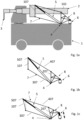
- the schematic views show embodiments of the present invention according to a direction of view perpendicular to the vertical plane passing through the axis of the arm 2.
- the support mechanism of the arm 2 which has a three-dimensional shape polyhedral, like a cage, it appears in its two-dimensional projection so that the lateral elevation shape of the corresponding side of the said structure is visible, which is congruent to that of the opposite side.
- the polyhedral cage which in the illustrated form preferably has four walls which are oriented perpendicular to the vertical plane passing through the longitudinal axis of the arm 2, (i.e. the plane of the sheet), and are connected to each other by means of articulation hinges with articulation axis also perpendicular to said vertical plane, is defined in the previous description and in the following description, as well as in the claims, as an articulated polyhedral cage.
- the shape is the preferred one of the executive example, i.e. when the polyhedral cage is cubic or parallelepiped in shape, it is defined as an articulated cubic cage or an articulated parallelepiped cage or an articulated parallelepiped or an articulated cube.
- walls of the articulated cage which is generically polyhedral or in particular cubic or parallelepiped, refers generically to closed two-dimensional sides or elements, i.e. with continuous or open surfaces, i.e. made in the form of square or rectangular frames or walls with a lattice structure, i.e. comprising a perimeter frame and transverse or longitudinal elements or wall parts which connect said frame elements to each other directly or by means of further crosspieces and/or longitudinal members and/or wall parts.
- the structures usable for said walls can be defined by the person skilled in the art according to the interface with further construction parts, such as the arm 2 and/or the actuators or in relation to the mechanical characteristics of weight and strength determined by the specific operating conditions without the person skilled in the art having to perform activities that go beyond his basic technical skills and knowledge.
- the articulated polyhedral cage 7 which constitutes the support and oscillation mechanism of the arm 2 is constituted by an articulated parallelepiped according to the definition of the present invention given above, i.e. by a combination of walls oriented perpendicularly to the vertical plane passing through the axis of the arm 2, the walls of which are articulated to each other on their ends by means of hinges, the axis of articulation of which is also perpendicular to said vertical plane passing through the axis of the arm 2.
- the articulated parallelepiped takes on the appearance of an articulated parallelogram.
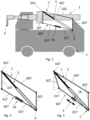
- Said articulated parallelepiped 7 is formed by four walls 107, 207, 307, 407 one of which is front and one rear with reference to the direction of orientation of the arm and/or advancement of the vehicle 1 which forms the base.
- the two walls 107 and 102 are oriented with a greater directional component in the vertical direction and the respective upper and lower ends are connected to each other by a third and a fourth wall of greater length indicated with 307, 407.
- These walls 307 and 407 are oriented in the front-rear direction of the vehicle, i.e. with a greater directional component in the direction of the axis of arm 2.
- a cylinder 5 which is arranged diagonally is provided, i.e. which connects two diametrically opposite articulation points of the articulated parallelepiped 7 and is provided both as a dynamic thrust aid and as a shock absorber to stabilize the movement imposed by the actuator 16.
- the cylinder 5 preferably connects the hinge 4 of the articulated parallelepiped to each other with an articulation point, i.e. with a hinge diametrically opposite to it indicated by 507.
- said cylinder 5 or means having identical functions is instead interposed between an element of the articulated parallelepiped 7, in particular the frame 507 and a stationary point of the base 1.
- the fixing point is provided in an intermediate position of the vehicle base, in correspondence with the front half of the same and offset back towards the transverse median plane in order to keep the center of gravity of the arm within the plan view of the vehicle 1 itself.
- the rear end of the arm 2 ends at the rear side of the base 1, i.e. of the vehicle, preferably with the rear end advanced by a certain distance in the front direction of the base 1, i.e. of the vehicle.
- the cage in the shape of an articulated parallelepiped has such a length that its rear wall 207 is provided advanced to a certain extent with respect to the rear end of the vehicle and/or the rear end section of the arm 2 and is fixed to a rear backing wall 101 of the vehicle 1 which has a vertical extension substantially identical to that of the rear wall 207 and a horizontal extension also possibly corresponding to the horizontal extension of the said rear wall 207. Therefore, the entire rear part 207 is stably constrained with respect to the vehicle 1 without being able to perform relative movements with respect to said vehicle. This constitutes a connection for transmitting the reaction forces and the static forces of the arm 2 on the vehicle which is particularly resistant and stable and which transfers and distributes said forces over a relatively large surface.
- the third lower wall 307 which connects the lower ends of the front arm-carrying wall 107 and of the rear wall 207 for fixing it to the base, can be extended and shortened in the direction of its own longitudinal axis, i.e. in the direction of connection of the articulation hinges to said front wall 107 and rear wall 207.
- a motorized joining mechanism 16 is provided between two wall parts 317 and 327 and allows said two wall parts to be translated parallel to themselves and in the plane defined by them with respect to each other, causing a variation in the geometry of the parallelepiped which causes a backward inclination of the lower end of the front wall 107 when said third wall is shortened and therefore the end hinges are brought closer to each other and vice versa a forward inclination when said third wall is lengthened and therefore the hinges at its ends are moved away from each other, whereby the front arm-carrying wall 107 is swung with its forward lower end.
- the oscillation of the front arm-carrying wall 107 therefore causes an oscillation of the arm 2 which is stably constrained to it.
- said front arm-carrying wall is fixed to the arm 2, 102 and forms a sliding head of the arm 2 in the axial direction forwards and backwards. Furthermore, the orientation of the arm 2 is such that the axis of the arm is substantially perpendicular to the plane defined by said front arm-carrying wall 107, whereby the arm is swung in the vertical plane by raising and lowering the slagging tool 3 depending on whether said third wall 307 is respectively shortened or lengthened.
- said third wall 307 of the cage in the form of an articulated parallelepiped 7.
- said third wall consists only of two side members parallel to each other and joined at their ends by the hinge articulation at the corresponding lower ends of the front arm-carrying walls 107 and rear fastening walls 207.
- both side members can be made telescopically extendable and shorten, being made of two tubular segments 317 and 327 engaged one in the other by a linear actuator 16 which can be a hydraulic or oleodynamic cylinder, a mechanical linear actuator, for example electromechanical or the like, being provided for example a motorized pinion which engages on diametrically opposite sides respectively a rack associated with a corresponding tubular segment.
- a linear actuator 16 which can be a hydraulic or oleodynamic cylinder, a mechanical linear actuator, for example electromechanical or the like, being provided for example a motorized pinion which engages on diametrically opposite sides respectively a rack associated with a corresponding tubular segment.
- the wall 307 is formed by two wall parts each made in the form of a frame, the two frames being connected in a sliding way to each other by means of sliding guides of one frame with respect to the other and being the said guides oriented parallel to the foreseen lengthening and shortening direction of said third wall 307.
- the relative displacement of the two frames can take place for example by means of hydraulic actuators or oleodynamic actuators or by means of mechanical or electromechanical actuators as described above.
- Figure 4 shows the condition in which the wall 307 has been shortened.
- the double arrow F indicates that said wall 307 can be lengthened and shortened.
- the arm 2 consists of a telescopic arm like the one described with reference to the embodiment according to the state of the art, whereby reference is made to said description in relation to said arm.
- Figure 3 shows an initial or neutral condition in which the wall 307 has an identical length to the opposite wall 407 and the articulated parallelepiped 7 shows a shape in side view of a regular parallelogram.
- Figures 5 and 6 relate to an embodiment in which the third lower wall 307 is made in two parts 317 and 327 which are connected to each other by a hinge 607 whose axis is oriented parallel to the axis of the other hinges, for example 507 and/or 4 of the articulated parallelepiped.
- a motorized actuator 16 for example a linear push and pull actuator, it is possible to change the relative orientation of the two wall parts 317 and 327, and this can cause the two end hinges of the wall 307 to move away from or approach each other and therefore a variation of the geometry of the articulated parallelepiped similarly to the previous embodiment.
- the third wall 307, or the wall parts 317 and 327 and any further wall parts in which the parts 317 and 327 can be further subdivided can have a construction according to one or more of the embodiments described with reference to the example of figures 2 to 4 .
- said wall parts can be in the form of pairs of lateral longitudinal members which connect at the ends with the hinges or by frames and the actuators can also be hydraulic, oledynamic or mechanical or electromechanical linear actuators or a combination thereof.
- the embodiment according to figures 7 to 9 provides that the lower wall 307 can be shortened and extended thanks to a particular configuration.
- this embodiment is preferably feasible when said third wall 307 is formed by two side members each of which is divided into two parts 317 and 327 which are connected to each other by a hinge 337, 347, the articulation axis of which is vertical, i.e. perpendicular to the articulation axis of the hinges between the walls 107, 207, 307, 407 of the articulated parallelepiped 7.
- the length of the segments 317 and 327 into which each side member is divided is identical for the two side members and the articulation axes of the hinges between said segments are contained in the same vertical plane parallel to the articulation axes of the hinges which connect the walls 107 to each other 107 , 207, 307, 407 of the articulated parallelepiped.
- Figure 9 shows more clearly the two hinges 337 and 347 and the fact that the two segments 317, 327 of each side member shorten and lengthen thanks to a variation of the relative angular position between them which takes place in the plane perpendicular to the vertical plane and containing the axes of said segments 317 and 327.
- the movement of the segments 317 and 327 of the two side members can take place similarly to what is described for the example of figures 5 and 6 and must take place substantially in a synchronized way for times and for measurement of the shortening or lengthening of the two side members.
- the maximum upward oscillation is that corresponding to the maximum possible length of the side members and therefore of the wall 307, therefore the position of maximum upward inclination of the arm is the one in which the arm is horizontal.
- the executive variant of figures 2 to 4 it is possible to provide a combination with that according to the executive variant of figures 2 to 4 , for example by making each of the segments 317 or 327 of the two side members in two parts and making said two parts movable relative to each other according to what is provided by the embodiment of figures 2 to 4 .
- all four segments 317 and 327 can be made extendable and shorten according to what is described with reference to figures 2 to 4 .
- the polyhedral cage 7 can comprise a cylinder 5 according to one of the variants described above.
- the cage structure has a more stable and resistant support to the base thanks to the fact that said support takes place for the entire surface of the rear wall 207 of the cage against a substantially identical surface of the base.
- Figures 10 to 13 show an embodiment of the embodiment illustrated schematically in figures 2 to 4 .
- the same reference numbers have been used for identical constructive parts or having identical functions.
- the head of the arm carries a fixing plate 30 of the slagging tool which is not shown in detail.
- Figures 10 to 13 show an embodiment of the invention, in which the arm 2 is slidably engaged in a guide duct formed in the front frame 107 of the articulated parallelepiped 7.
- This consists of two plates connected to each other by crosspieces 117.
- At least a guide roller or at least a pair of guide rollers spaced apart in the front-rear direction of the arm 2 and indicated with 127 are provided in the upper and lower part of the frame 107.
- the arm 2 has a square or rectangular cross section with the horizontal sides sliding against the corresponding lower and upper guide rollers 127 so as to hold the arm 2 in an axially aligned position without allowing its oscillations relative to the frame 107 in the vertical plane parallel to the longitudinal axis of the arm 2 itself.
- the two plates 137 which form the side walls of the front frame 107 are connected to each other not only by the crosspieces 117 but also by the hinges 507 and at the front end by a front wall 147 which has a passage window for the arm 2.
- the elongation of the arm 2 is caused by a lateral rack 302 or by two lateral racks, one on respectively one of the two opposite lateral faces of the arm 2, which racks cooperate with a corresponding pinion (not shown in detail) which is actuated at rotation by a gearmotor 402 mounted on a corresponding side plate of the frame 107.
- the upper frame 407 consists of a substantially rectangular frame having two parallel longitudinal members in the front-rear direction of the arm 2, the ends of which are respectively connected by a crosspiece.
- the front crosspiece of the upper branch 407 forms a part of the articulation hinge 507 to the front frame 107, while the rear crosspiece is pivotally articulated around an axis parallel to the axis of articulation of the upper front hinge 507 and the lower rear one 4 to the rear frame 207.
- a plate 217 which has, on the side facing the ends of the frames 307 and 407 oriented mainly in the direction of the axis of the arm 2, along the substantially vertical side edges walls 227 protruding from said plate, cantilevered towards the frames 307 and 407 form respective articulation hinge parts to said frames 307 and 407.
- the vertical end plate 217 is oriented perpendicular to the vertical plane which passes through the axis of the arm 2 and has slots and holes for fastening to the frame of a base such as, but not limited to, the vehicle 1 of figures 2 to 4 .
- the lower frame 307 is formed by two longitudinal members on the two sides of said frame oriented parallel to the axis of the arm 2 and which are each formed by two segments 317 and 327 made to slide one into the other.
- the most front segments 317 of said side members are articulated to the corresponding lateral plate which forms the front frame 107 and in an oscillating manner around a common articulation axis parallel to the articulation axis of the hinge 507 and 4.
- the segments 327 of the two longitudinal members are slidingly engaged in the cavity of the segments 327 which are tubular.
- the two segments 327 are connected by a crosspiece at their opposite end to that engaged in the segments 317.
- the end crosspiece connecting the segments 327 forms the terminal hinge 4 for articulation of the frame 307 to the rear frame 207 and has such a length, that the distance between the side members is greater than the corresponding horizontal dimension of the cross section of arm 2.
- An oleodynamic linear actuator 16 is provided between the end of each rear segment 327 and the corresponding segment 317, in particular a perimetric flange at the end of the segment 317 facing the associated rear segment 327.
- the actuation of said linear actuators 16 in a synchronized manner determines the relative forward and backward sliding of the segments 317 with respect to the segments 327 and the lengthening and shortening of the side members with the consequent variation of the inclination of the front frame 107 and therefore of the arm 2 engaged in sliding in the same.
Landscapes
- Engineering & Computer Science (AREA)
- Mechanical Engineering (AREA)
- General Engineering & Computer Science (AREA)
- Vertical, Hearth, Or Arc Furnaces (AREA)
- Manufacture And Refinement Of Metals (AREA)
- Jib Cranes (AREA)
Applications Claiming Priority (1)
| Application Number | Priority Date | Filing Date | Title |
|---|---|---|---|
| IT102021000031535A IT202100031535A1 (it) | 2021-12-16 | 2021-12-16 | Dispositivo per la movimentazione di un utensile di omogenizzazione e/o scorificatore di metallo fuso in particolare di alluminio nei forni di fusione |
Publications (1)
| Publication Number | Publication Date |
|---|---|
| EP4198430A1 true EP4198430A1 (fr) | 2023-06-21 |
Family
ID=80461364
Family Applications (1)
| Application Number | Title | Priority Date | Filing Date |
|---|---|---|---|
| EP22213719.2A Withdrawn EP4198430A1 (fr) | 2021-12-16 | 2022-12-15 | Dispositif de deplacement d'un outil d'homogenisation et/ou de décrassage de metaux en fusion, notamment d'aluminium, dans un four de fusion |
Country Status (2)
| Country | Link |
|---|---|
| EP (1) | EP4198430A1 (fr) |
| IT (1) | IT202100031535A1 (fr) |
Cited By (1)
| Publication number | Priority date | Publication date | Assignee | Title |
|---|---|---|---|---|
| CN117128764A (zh) * | 2023-10-27 | 2023-11-28 | 山西诚至昊机电设备有限公司 | 一种拆炉机 |
Citations (2)
| Publication number | Priority date | Publication date | Assignee | Title |
|---|---|---|---|---|
| GB2027178A (en) * | 1978-08-01 | 1980-02-13 | Shanks & Mcewan | Breaking apparatus for removing scale from reheating furnace |
| US4223875A (en) * | 1978-05-30 | 1980-09-23 | Alexander Shand Services Limited | Apparatus for deskulling tundishes and similar vessels |
-
2021
- 2021-12-16 IT IT102021000031535A patent/IT202100031535A1/it unknown
-
2022
- 2022-12-15 EP EP22213719.2A patent/EP4198430A1/fr not_active Withdrawn
Patent Citations (2)
| Publication number | Priority date | Publication date | Assignee | Title |
|---|---|---|---|---|
| US4223875A (en) * | 1978-05-30 | 1980-09-23 | Alexander Shand Services Limited | Apparatus for deskulling tundishes and similar vessels |
| GB2027178A (en) * | 1978-08-01 | 1980-02-13 | Shanks & Mcewan | Breaking apparatus for removing scale from reheating furnace |
Cited By (2)
| Publication number | Priority date | Publication date | Assignee | Title |
|---|---|---|---|---|
| CN117128764A (zh) * | 2023-10-27 | 2023-11-28 | 山西诚至昊机电设备有限公司 | 一种拆炉机 |
| CN117128764B (zh) * | 2023-10-27 | 2024-01-02 | 山西诚至昊机电设备有限公司 | 一种拆炉机 |
Also Published As
| Publication number | Publication date |
|---|---|
| IT202100031535A1 (it) | 2023-06-16 |
Similar Documents
| Publication | Publication Date | Title |
|---|---|---|
| US5110294A (en) | Device for ground-based simulation of operations of a manipulator usable in space by means of a model of a space vehicle | |
| CZ295724B6 (cs) | Zvedací zařízení | |
| US4121680A (en) | Vehicles | |
| EP2105352B1 (fr) | Plancher porte-charge mobile pour le coffre d'un véhicule à moteur | |
| CN112192608B (zh) | 机器人头颈结构和机器人 | |
| EP0305437B1 (fr) | Manipulateur de lingots en metal | |
| JP7196309B2 (ja) | 頭上外骨格 | |
| IT202100031535A1 (it) | Dispositivo per la movimentazione di un utensile di omogenizzazione e/o scorificatore di metallo fuso in particolare di alluminio nei forni di fusione | |
| EP1940724B1 (fr) | Chariot elevateur a fourche electrique et procede de fabrication de celui-ci | |
| CN214298858U (zh) | 汽车侧围平衡吊具 | |
| US3866689A (en) | Wing frame control mechanism for ground working implement | |
| NL1011648C2 (nl) | Kantelmechanisme. | |
| JPH06219684A (ja) | クレーン−ボーリング装置用等の作業車両のマスト支持装置 | |
| JPS62296955A (ja) | 作業床昇降装置 | |
| JPH0788784A (ja) | ロボット作業車 | |
| CN223496024U (zh) | 一种新式轻型菱形挂篮 | |
| SU1082542A1 (ru) | Ковочный манипул тор | |
| CN213381638U (zh) | 机器人的重心调节机构 | |
| JP2013528503A (ja) | 多関節アームロボット | |
| CN223137507U (zh) | Led模拟装置 | |
| WO1989011435A1 (fr) | Grue | |
| KR970003792Y1 (ko) | 시저리프트의 플랫폼확장장치 | |
| JPH0262476B2 (fr) | ||
| JP2984589B2 (ja) | 展示ケースの展示パネル装置 | |
| JPH0441397A (ja) | 同時連係昇降機構を備えたテーブルリフター |
Legal Events
| Date | Code | Title | Description |
|---|---|---|---|
| PUAI | Public reference made under article 153(3) epc to a published international application that has entered the european phase |
Free format text: ORIGINAL CODE: 0009012 |
|
| STAA | Information on the status of an ep patent application or granted ep patent |
Free format text: STATUS: THE APPLICATION HAS BEEN PUBLISHED |
|
| AK | Designated contracting states |
Kind code of ref document: A1 Designated state(s): AL AT BE BG CH CY CZ DE DK EE ES FI FR GB GR HR HU IE IS IT LI LT LU LV MC ME MK MT NL NO PL PT RO RS SE SI SK SM TR |
|
| STAA | Information on the status of an ep patent application or granted ep patent |
Free format text: STATUS: THE APPLICATION IS DEEMED TO BE WITHDRAWN |
|
| 18D | Application deemed to be withdrawn |
Effective date: 20231222 |