EP4198464B1 - Balance de bande transporteuse pourvue de détecteur de métal - Google Patents
Balance de bande transporteuse pourvue de détecteur de métal Download PDFInfo
- Publication number
- EP4198464B1 EP4198464B1 EP21216108.7A EP21216108A EP4198464B1 EP 4198464 B1 EP4198464 B1 EP 4198464B1 EP 21216108 A EP21216108 A EP 21216108A EP 4198464 B1 EP4198464 B1 EP 4198464B1
- Authority
- EP
- European Patent Office
- Prior art keywords
- conveyor belt
- coils
- piece goods
- coil
- metal detector
- Prior art date
- Legal status (The legal status is an assumption and is not a legal conclusion. Google has not performed a legal analysis and makes no representation as to the accuracy of the status listed.)
- Active
Links
Images


Classifications
-
- G—PHYSICS
- G01—MEASURING; TESTING
- G01G—WEIGHING
- G01G19/00—Weighing apparatus or methods adapted for special purposes not provided for in the preceding groups
- G01G19/02—Weighing apparatus or methods adapted for special purposes not provided for in the preceding groups for weighing wheeled or rolling bodies, e.g. vehicles
- G01G19/03—Weighing apparatus or methods adapted for special purposes not provided for in the preceding groups for weighing wheeled or rolling bodies, e.g. vehicles for weighing during motion
-
- G—PHYSICS
- G01—MEASURING; TESTING
- G01G—WEIGHING
- G01G11/00—Apparatus for weighing a continuous stream of material during flow; Conveyor belt weighers
- G01G11/003—Details; specially adapted accessories
-
- G—PHYSICS
- G01—MEASURING; TESTING
- G01V—GEOPHYSICS; GRAVITATIONAL MEASUREMENTS; DETECTING MASSES OR OBJECTS; TAGS
- G01V3/00—Electric or magnetic prospecting or detecting; Measuring magnetic field characteristics of the earth, e.g. declination, deviation
- G01V3/08—Electric or magnetic prospecting or detecting; Measuring magnetic field characteristics of the earth, e.g. declination, deviation operating with magnetic or electric fields produced or modified by objects or geological structures or by detecting devices
- G01V3/10—Electric or magnetic prospecting or detecting; Measuring magnetic field characteristics of the earth, e.g. declination, deviation operating with magnetic or electric fields produced or modified by objects or geological structures or by detecting devices using induction coils
Definitions
- the present invention relates to a conveyor belt scale for transporting piece goods with a feed belt, a weighing belt and a discharge belt.
- the weighing belt is supported on a load cell that detects the weight of piece goods that are transported via the weighing belt.
- the conveyor belt scale comprises a metal detector that comprises at least one transmitter coil and at least one receiver coil.
- Metal detectors are used in the food industry to detect metallic contamination in food.
- Metallic contamination occurs, for example, when part of a component in a meat processing machine breaks off and falls into the food.
- small screws can come loose during operation or small fragments can break off from a knife, for example. These fragments are often only a few millimeters in size, for example 2 mm to 4 mm.
- Food with such contamination must be identified and sorted out at the end of the production process.
- conveyor belt scales or price labelers for checking the weight and, if necessary, for labeling packaging, for example trays containing food are often equipped with a metal detector.
- These metal detectors work with X-ray technology or with a tunnel formed by a circular coil, so that the food is conveyed vertically through the coil by the conveyor belt. This is usually only possible with a complex structure.
- a conveyor belt scale comprises a feed belt which passes through a metal detector which is designed as a tunnel.
- the RU2583346C2 shows a metal detector for detecting a metal object that is located inside another object.
- a metal object For example, a water, electricity or gas pipe can be detected in a wall.
- the DE102020113024A1 shows a metal detector designed as a tunnel through which a conveyor belt passes.
- the object of the invention is to provide a conveyor belt scale for piece goods, in particular for foodstuffs, which are packaged in particular in trays, which comprises a metal detector which is integrated in a simple manner.
- a conveyor belt scale for transporting piece goods, with a feed belt, a weighing belt and a discharge belt.
- the weighing belt is supported on a load cell that records the weight of piece goods that are transported via the weighing belt.
- the conveyor belt scale comprises a metal detector that comprises at least one transmitter coil and at least one receiver coil.
- the at least one transmitter coil and the at least one receiver coil are each designed as a planar coil.
- the person skilled in the art understands a planar coil to be a coil with only one turn, i.e. a circular or rectangular conductor structure that is not closed, but whose two ends are guided together except for a small distance.
- the planar coils are each located in a plane that runs parallel to the upper run of the conveyor belt and thus parallel to the conveying direction. Planar coils have the advantage that they can be manufactured relatively easily, reliably, inexpensively and with low tolerances.
- At least one planar coil is designed as a conductor structure on a circuit board.
- all planar coils are designed as conductor structures on at least one circuit board.
- the planar structures can be easily manufactured using a known process and almost any conductor structure can be formed in one plane.
- the planar coil is formed in a metallization plane of the circuit board.
- the conveyor belt scale comprises a conveyor belt.
- the conveyor belt comprises a belt body around which a conveyor belt is guided via deflection rollers mounted at the beginning and end. At least one coil of the metal detector is integrated in the belt body between the upper run and the lower run of the conveyor belt.
- all coils of the metal detector are integrated into the belt body between the upper and lower run of the conveyor belt. This has the advantage that the item on the upper run of the conveyor belt slides over the coils of the metal detector and no further structures are necessary in the conveyor area of the conveyor belt.
- a receiver coil is electrically assigned to a transmitter coil.
- the receiver coil assigned to the transmitter coil is arranged on the same circuit board and essentially in the same geometric area of the circuit board, but on a different metallization level.
- electrically assigned is to be understood as meaning that the receiver coil detects a magnetic reaction caused by the transmitter coil in a metal object.
- the transmitter coil and receiver coil are arranged one above the other, so to speak. This should also include the transmitter coil and receiver coil being slightly offset from one another, for example, but essentially still overlapping. Furthermore, this should also be understood to mean that the transmitter coil and receiver coil are arranged rotated relative to one another.
- half of the coils of the metal detector are integrated into the belt body between the upper run and the lower run of the conveyor belt.
- Half of the coils of the metal detector are arranged above the upper run and at a distance from the upper run of the conveyor belt.
- Above the upper run is to be understood as meaning that there is enough free space between the upper run of the conveyor belt and the coils that the item can be conveyed under the coils of the metal detector, but the coils are arranged close enough to the conveyor belt so that the magnetic field of the coils can interact with the item.
- the coils arranged within the band body and the coils arranged above the The coils are arranged on the upper run of the conveyor belt, essentially at the same height in the direction of transport. This means that the coils are on top of each other when viewed in the direction of transport. If there are several coils, at least some of them are arranged next to each other perpendicular to the direction of transport.
- a first number of two or more coils are arranged in the belt body between the upper run and the lower run of the conveyor belt.
- the same number of coils are arranged above the upper run of the belt body.
- Each coil in the belt body between the upper run and the lower run of the conveyor belt is electrically assigned a coil above the upper run of the belt body.
- transmitter coils and/or receiver coils consist of extended electrical conductor structures. These are arranged in particular in a circular or rectangular shape. These are arranged in particular on a printed circuit board.
- the conductor structures are essentially designed as a rectangular function, in particular as a regular rectangular function.
- the rectangular function runs along a circular path or a rectangular path.
- the metal detector comprises a signal generator that generates an alternating current signal.
- the alternating current signal is fed to the at least one transmitter coil.
- the alternating current signal fed to the at least one transmitter coil generates a magnetic field.
- the magnetic field induces eddy currents in a metallic object to be detected in a piece of goods on the conveyor belt.
- the piece of goods is an object to be checked, for example a foodstuff.
- the metallic object is, for example, a contaminant in the foodstuff that can pose a danger to a consumer and should therefore be detected.
- the metal detector comprises a signal evaluation device.
- the signal evaluation device detects a magnetic field generated by the eddy currents in the metallic object in the cargo, which is received by the receiver coil.
- the signal generator generates a pulsed AC signal. That is, the signal generator generates an AC signal that is periodically turned on and off.
- the signal evaluation device does not carry out any signal evaluation at the time when the pulsed alternating current signal of the signal generator is greater than zero. This is to be understood as meaning that no signal evaluation is carried out when the transmitter coil generates a magnetic field. This magnetic field of the transmitter coil would interfere with the signal evaluation of the signal evaluation device.
- the signal of the signal generator is greater than zero when the signal of the signal generator is switched on and is equal to zero when the signal of the signal generator is switched off. Since, due to the practical implementation, infinitely steep edges are not possible with a pulsed signal, the person skilled in the art understands that zero is to be understood as a threshold value in the range of a very low signal strength.
- the transmitter coils and the receiver coils are electrically shielded from each other.
- the conveyor belt scale comprises a light barrier or a distance sensor for detecting a package in the detection range of the metal detector.
- the conveyor belt scale comprises a control device that puts the metal detector into an active state when the light barrier or the distance sensor detects a piece of goods conveyed on the conveyor belt scale in the area of the metal detector.
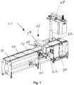
- Fig. 1 shows a conveyor belt scale 10 consisting of a feed belt 12, a weighing belt 14 supported on a load cell and a discharge belt 16. Following the discharge belt 16 there is a metal detector 18 which comprises a conveyor belt 20 which receives piece goods from the discharge belt and transports them downstream.
- the metal detector 18 comprises a housing 24 in which a coil arrangement (not shown) is located.
- the housing 24 has a through opening 26 for piece goods and for the conveyor belt 20.
- the piece goods are transported on the conveyor belt 20 along the conveying direction through the through opening 26 of the housing 24.
- the coil arrangement consists of coils arranged one behind the other in the conveying direction, namely a first receiver coil, followed by a transmitter coil and then a second receiver coil. All coils are arranged parallel to one another and consist of circular windings which are mounted inside the housing 24. The coils are formed in a plane perpendicular to the conveying direction. Each coil wraps around the through opening 26.
- the coils comprise a plurality of windings made of a metallic wire.
- the metal detector comprises a control device 22 in which the signal generation for the transmitter coil and the signal processing of signals from the receiver coils takes place. Following the metal detector 18, a printer station is mounted which in turn comprises a conveyor belt 32 and comprises a top labeler 28 for labeling piece goods from above and a bottom labeler 30 for labeling piece goods from below.
- Fig. 2 shows a conveyor belt 40 with an integrated metal detector according to a first embodiment of the invention.
- the conveyor belt consists of a belt body which consists of a frame 46. At both longitudinal ends of the frame 46, i.e. at the beginning and end of the frame 46, deflection rollers 42, 44 are attached, around which a conveyor belt 48 is guided in a rotating manner.
- the conveyor belt 48 is interrupted to illustrate the area 50 within the frame 46. In reality, however, the conveyor belt 48 is closed and can thus be guided in an endless rotation around the deflection rollers 42, 44, one of which is driven. Piece goods are transported on the conveyor belt 48 in the transport direction.
- a circuit board 52 is mounted transversely to the transport direction of the conveyor belt 40, which in this case comprises two coils 54, 56.
- the number of coils 54, 56 depends on their size and the width of the conveyor belt 48.
- the coils 54, 56 are electrically connected to the control device 22.
- the transmission signal of each coil 54, 56 is generated in the control device 22.
- the reception signals of each coil 54, 56 are evaluated in the control device 22.
- the control device 22 comprises a signal generator which generates an alternating current signal which is fed to the at least one transmitter coil 54, 56.
- the alternating current signal fed to the at least one transmitter coil 54, 56 generates a magnetic field which induces eddy currents in a metallic object to be detected in a piece of goods on the conveyor belt 48.
- the control device 22 comprises a signal evaluation device which detects and evaluates a magnetic field generated by the eddy currents in the metallic object in the piece of goods, which is received by the receiver coil 54, 56.
- a plate (not shown), in particular a metal plate, is mounted on the frame 46, on which the conveyor belt 48 slides and by which the conveyor belt 48 is supported.
- the plate can also be mounted continuously above the circuit board 52. If the plate is made of a material that interferes with the electromagnetic field of the coils, in particular metal, the plate must be interrupted in the area of the coils.
- the metal detector integrated into the conveyor belt 40 comprises only one circuit board 52 below the upper run of the conveyor belt 48 in the area 50 within the frame 46. On this circuit board 52, transmitter coils and receiver coils are designed as conductor structures, as in Fig. 3a and Fig. 3b shown in a first and a second embodiment.
- Fig. 3a shows a conductor structure of a coil 54, 56, which serves as both a transmitter coil 62 and a receiver coil 60.
- Two similar conductor structures are arranged electrically insulated from each other, which have the same or a similar contour. These conductor structures are electrically insulated from each other by being mounted on a circuit board 52 with several metallization levels arranged on different metallization levels.
- the conductor structure 60 which is drawn with the solid line, shows the uppermost metallization level. This is the receiver coil 60.
- the conductor structure 62 which is drawn with the dashed line, shows a conductor structure on an underlying metallization level. This is the transmitter coil 62. In principle, the transmitter coil and receiver coil can also be swapped.
- the receiver coil 60 is connected to the control device 22 via an electrical connection 66.
- the transmitter coil 62 is connected to the control device 22 via an electrical connection 64.
- the conductor structures 60, 62 of the transmitter coil 62 and receiver coil 60 follow a periodic, i.e. regular, rectangular function. This rectangular function is arranged on a circular path.
- the conductor structures 60, 62 are thus star-shaped, with the tips being flat.
- the transmitter coil 62 and the receiver coil 60 are arranged directly above one another, i.e. geometrically overlapping or slightly twisted and/or shifted relative to one another. In one embodiment, the sizes of the transmitter coil 62 and the receiver coil 60 could differ slightly.
- Fig. 3b shows a conductor structure of a coil 68, which serves both as a transmitter coil 76 and as a receiver coil 74.
- the arrangement on a circuit board 52 on different metallization levels basically corresponds to the embodiment of Fig. 3a
- the conductor structures of the transmitter coil 76 and receiver coil 74 are also designed as a periodic rectangular function. However, in contrast to Fig. 3a along a rectangle.
- a transmitter coil 76 and a receiver coil 74 can form a Most of the extent of the circuit board 52 under the conveyor belt 48 and thus generate an electromagnetic field across the entire width of the conveyor belt 48.
- the transmitter coil 76 is connected to the control device 22 via an electrical connection 72.
- the receiver coil 74 is connected to the control device 22 via an electrical connection 70.
- Fig. 4 shows a conveyor belt with an integrated metal detector according to a second embodiment of the invention.
- the conveyor belt comprises a first circuit board 90 within the frame of the belt body of the conveyor belt.
- the metal detector comprises a second circuit board 92 above the upper run of the conveyor belt 48.
- the piece goods conveyed on the conveyor belt 48 are conveyed through the area between the first circuit board 90 and the second track 92, while the conveyor belt 48 is guided around input-side and output-side deflection rollers 42, 44.
- a control device 94 is electrically connected to the circuit boards 90, 92.
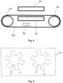
- Fig. 5 shows a circuit board 90, 92 of the metal detector of the second embodiment.
- the coils 80, 84 are designed as a regular, ie periodic rectangular function, which as in Fig. 5 shown runs along a circular path. Alternatively, the conductor structure of the coils 80, 84 can also run along a rectangle or oval.
- the coils 80, 84 are connected to the control device 94 via the connections 82, 86 and are electrically controlled.
- the conductor structures on the first circuit board 90 and the associated conductor structures on the second circuit board 92 (transmitter coils and receiver coils) are arranged geometrically one above the other in the conveying direction so that they interact.
- a coil 80, 84 on the first circuit board 90 and a coil 80, 84 on the second circuit board 92 serve as the associated transmitter coil and receiver coil.
- all transmitter coils on the first circuit board 90 and all receiver coils on the second circuit board 92 are arranged. In one embodiment, all transmitter coils can be arranged on the second circuit board 92 and all receiver coils on the first circuit board 90. Transmitter coils and receiver coils can also be arranged alternately on the first circuit board 90 and the associated receiver coils and transmitter coils are then each arranged on the second circuit board 92 and thus also alternately there.
- the printed circuit board shown with conductor structures in only one metallization level can also be used in the first embodiment according to Fig. 2 as a circuit board 52.
- the conductor structures 80, 84 serve as transmitter coils and receiver coils.
- the transmission signal is generated via the signal generator of the control device 22 and pulsed to the coils 80, 84, or the signal generator generates a pulsed alternating current signal. After the transmission signal has been applied to the coils 80, 84, the signal is switched off and the signal received by the coils is evaluated.
- Both coils 80, 84 thus serve as a transmitter coil and a receiver coil, offset in time. In this embodiment, decoupling between the transmission signal and the reception signal does not take place via electrical decoupling of the coils, but rather via the time offset.
- the conveyor belts with integrated metal detector according to the embodiments according to Fig. 2 or Fig. 4 can be arranged in place of the feed belt 12, the discharge belt 16 or the separate metal detector belt 20 and replace the respective belt.
- DSP digital signal processor
- ASIC application specific integrated circuit
- FPGA field programmable gate array
- ROM read only memory
- RAM random access memory
Landscapes
- Physics & Mathematics (AREA)
- General Physics & Mathematics (AREA)
- Engineering & Computer Science (AREA)
- Remote Sensing (AREA)
- Life Sciences & Earth Sciences (AREA)
- Electromagnetism (AREA)
- Environmental & Geological Engineering (AREA)
- Geology (AREA)
- General Life Sciences & Earth Sciences (AREA)
- Geophysics (AREA)
- Control Of Conveyors (AREA)
- Geophysics And Detection Of Objects (AREA)
Claims (14)
- Balance à bande transporteuse servant au transport de marchandises de détail, comportant une bande d'alimentation (12), une bande de pesage (14) et une bande d'évacuation (16), la bande de pesage (14) étant supportée sur une cellule de pesage qui détecte le poids des marchandises de détail qui sont transportées par la bande de pesage (14), la balance à bande transporteuse comportant un détecteur de métal qui comporte au moins une bobine émettrice (54, 56) et au moins une bobine réceptrice (54, 56), et la balance à bande transporteuse comportant une bande transporteuse qui comporte un corps de bande (46) autour duquel est guidée de manière rotative une bande transporteuse (48) par le biais de rouleaux de déviation (42, 44) montés côté début et extrémité, caractérisée en ce que l'au moins une bobine émettrice (54, 56) et l'au moins une bobine réceptrice (54, 56) sont réalisées respectivement sous la forme d'une bobine plane (60, 62, 74, 76, 80, 84), lesquelles se trouvent respectivement dans un plan qui s'étend parallèlement au brin supérieur de la bande transporteuse et donc parallèlement à la direction de transport, et en ce qu'au moins une bobine du détecteur de métal est intégrée dans le corps de bande entre le brin supérieur et le brin inférieur de la bande transporteuse (48).
- Balance à bande transporteuse servant au transport de marchandises de détail selon la revendication 1, caractérisée en ce qu'au moins une, en particulier toutes les bobines planes (60, 62, 74, 76, 80, 84) sont réalisées sous forme de structures conductrices sur au moins une carte de circuit imprimé (52, 90, 92).
- Balance à bande transporteuse servant au transport de marchandises de détail selon la revendication 1 ou 2, caractérisée en ce que toutes les bobines du détecteur de métal sont intégrées dans le corps de bande entre le brin supérieur et le brin inférieur de la bande transporteuse (48).
- Balance à bande transporteuse servant au transport de marchandises de détail selon la revendication 3, caractérisée en ce qu'une bobine réceptrice est associée électriquement respectivement à une bobine émettrice, et la bobine réceptrice associée à la bobine émettrice est disposée sur la même carte de circuit imprimé et sensiblement dans la même région géométrique de la carte de circuit imprimé (52), mais sur un autre plan de métallisation.
- Balance à bande transporteuse servant au transport de marchandises de détail selon la revendication 1 ou 2, caractérisée en ce que la moitié des bobines du détecteur de métal sont intégrées dans le corps de bande entre le brin supérieur et le brin inférieur de la bande transporteuse (48) et la moitié des bobines du détecteur de métal sont disposées au-dessus du brin supérieur et à distance du brin supérieur de la bande transporteuse (48).
- Balance à bande transporteuse servant au transport de marchandises de détail selon la revendication 5, caractérisée en ce que les bobines qui sont disposées à l'intérieur du corps de bande (46) et les bobines qui sont disposées au-dessus du brin supérieur de la bande transporteuse (48) sont disposées sensiblement à la même hauteur dans la direction de transport.
- Balance à bande transporteuse servant au transport de marchandises de détail selon la revendication 6, caractérisée en ce qu'un premier nombre de deux bobines ou plus, en particulier quatre bobines, sont disposées dans le corps de bande entre le brin supérieur et le brin inférieur de la bande transporteuse (48), et un deuxième nombre de bobines, qui correspond au premier nombre, est disposé au-dessus du brin supérieur du corps de bande, une bobine au-dessus du brin supérieur du corps de bande étant associée électriquement à chaque bobine dans le corps de bande entre le brin supérieur et le brin inférieur de la bande transporteuse (48).
- Balance à bande transporteuse servant au transport de marchandises de détail selon l'une des revendications 1 à 7, caractérisée en ce que les bobines émettrices et/ou les bobines réceptrices sont constituées de structures conductrices électriques étendues qui sont disposées en particulier de manière circulaire ou rectangulaire, en particulier sur une carte de circuit imprimé (52, 90, 92).
- Balance à bande transporteuse servant au transport de marchandises de détail selon la revendication 8, caractérisée en ce que les structures conductrices sont formées sensiblement sous la forme d'une fonction rectangulaire, en particulier d'une fonction rectangulaire régulière, et la fonction rectangulaire s'étend le long d'une trajectoire circulaire ou d'une trajectoire rectangulaire.
- Balance à bande transporteuse servant au transport de marchandises de détail selon l'une des revendications 1 à 9, caractérisée en ce que le détecteur de métal comprend un générateur de signaux qui produit un signal de courant alternatif, lequel est acheminé à l'au moins une bobine émettrice, le signal de courant alternatif acheminé à l'au moins une bobine émettrice produisant un champ magnétique, lequel induit des courants de Foucault dans un objet métallique à détecter dans une marchandise de détail sur la bande transporteuse, et en ce que le détecteur de métal comprend un dispositif d'évaluation de signaux, lequel détecte un champ magnétique produit par les courants de Foucault dans l'objet métallique dans la marchandise de détail, lequel champ magnétique est reçu par la bobine réceptrice.
- Balance à bande transporteuse servant au transport de marchandises de détail selon la revendication 10, caractérisée en ce que le générateur de signaux produit un signal de courant alternatif pulsé.
- Balance à bande transporteuse servant au transport de marchandises de détail selon la revendication 11, caractérisée en ce que le dispositif d'évaluation de signaux n'effectue aucune évaluation de signaux à l'instant auquel le signal de courant alternatif pulsé du générateur de signaux est supérieur à zéro.
- Balance à bande transporteuse servant au transport de marchandises de détail selon l'une des revendications 1 à 12, caractérisée en ce que les bobines émettrices et les bobines réceptrices sont blindées électriquement les unes par rapport aux autres.
- Balance à bande transporteuse servant au transport de marchandises de détail selon l'une des revendications 1 à 13, caractérisée en ce que la balance à bande transporteuse comporte une barrière lumineuse ou un capteur de distance servant à la détection d'un emballage dans la région de détection du détecteur de métal, et en ce que la balance à bande transporteuse comporte un dispositif de commande qui met le détecteur de métal dans un état actif lorsque la barrière lumineuse ou le capteur de distance détecte une marchandise de détail transportée sur la balance à bande transporteuse dans la région du détecteur de métal.
Priority Applications (2)
| Application Number | Priority Date | Filing Date | Title |
|---|---|---|---|
| EP21216108.7A EP4198464B1 (fr) | 2021-12-20 | 2021-12-20 | Balance de bande transporteuse pourvue de détecteur de métal |
| US18/080,795 US12523520B2 (en) | 2021-12-20 | 2022-12-14 | Conveyor belt scales comprising a metal detector |
Applications Claiming Priority (1)
| Application Number | Priority Date | Filing Date | Title |
|---|---|---|---|
| EP21216108.7A EP4198464B1 (fr) | 2021-12-20 | 2021-12-20 | Balance de bande transporteuse pourvue de détecteur de métal |
Publications (2)
| Publication Number | Publication Date |
|---|---|
| EP4198464A1 EP4198464A1 (fr) | 2023-06-21 |
| EP4198464B1 true EP4198464B1 (fr) | 2025-01-29 |
Family
ID=78957446
Family Applications (1)
| Application Number | Title | Priority Date | Filing Date |
|---|---|---|---|
| EP21216108.7A Active EP4198464B1 (fr) | 2021-12-20 | 2021-12-20 | Balance de bande transporteuse pourvue de détecteur de métal |
Country Status (2)
| Country | Link |
|---|---|
| US (1) | US12523520B2 (fr) |
| EP (1) | EP4198464B1 (fr) |
Family Cites Families (14)
| Publication number | Priority date | Publication date | Assignee | Title |
|---|---|---|---|---|
| US3573784A (en) * | 1968-10-02 | 1971-04-06 | Henry L Bachofer | Metal detecting apparatus for conveyor belt |
| US5397986A (en) * | 1991-11-01 | 1995-03-14 | Federal Labs Systems Lp | Metal detector system having multiple, adjustable transmitter and receiver antennas |
| EP1101715B1 (fr) * | 1998-05-29 | 2004-09-01 | Anritsu Industrial Solutions Co.,Ltd. | Transporteur, machine de pesage et machine de detection de metal utilisant le transporteur |
| JP2002156461A (ja) * | 2000-11-15 | 2002-05-31 | Seisaku Tanaka | 金属検出装置 |
| US6774624B2 (en) * | 2002-03-27 | 2004-08-10 | Ge Medical Systems Global Technology Company, Llc | Magnetic tracking system |
| AU2003294237A1 (en) * | 2002-11-07 | 2004-06-03 | The Johns Hopkins University | Moving belt sensor |
| DE102007021393C5 (de) * | 2007-05-04 | 2018-11-15 | Wipotec Gmbh | Transportwaage, insbesondere Wägeförderer mit einem Transportband |
| DE102010031142A1 (de) * | 2010-05-07 | 2011-11-10 | Robert Bosch Gmbh | Erfassung eines metallischen oder magnetischen Objekts |
| US9004271B2 (en) * | 2011-08-25 | 2015-04-14 | Laitram, L.L.C. | Weighing system using a conveyor belt with load cells |
| EP2650660A1 (fr) * | 2012-04-13 | 2013-10-16 | Mettler-Toledo Garvens GmbH | Bande de détecteur de métaux avec cellule de pesage intégrée |
| EP2865614B1 (fr) * | 2013-10-25 | 2017-06-28 | Mettler-Toledo Garvens GmbH | Bâti pour une installation de tapis de transport |
| US10768038B2 (en) * | 2017-10-27 | 2020-09-08 | Industrial Technology Research Institute | Conveyor with a weighing system for weighing cargoes and weighing method thereof |
| EP3578932A1 (fr) * | 2018-06-07 | 2019-12-11 | Bizerba SE & Co. KG | Dispositif de transport et de pesage |
| DE102020113024A1 (de) * | 2020-05-13 | 2021-11-18 | Minebea Intec Aachen GmbH & Co. KG | Spulenkörper für ein Metallsuchgerät |
-
2021
- 2021-12-20 EP EP21216108.7A patent/EP4198464B1/fr active Active
-
2022
- 2022-12-14 US US18/080,795 patent/US12523520B2/en active Active
Also Published As
| Publication number | Publication date |
|---|---|
| US12523520B2 (en) | 2026-01-13 |
| US20230194329A1 (en) | 2023-06-22 |
| EP4198464A1 (fr) | 2023-06-21 |
Similar Documents
| Publication | Publication Date | Title |
|---|---|---|
| DE2358185C2 (de) | Sortiergerät mit Vereinzelungsbahn und Sortierbahn | |
| EP2228308B1 (fr) | Ligne de fabrication avec un dispositif de contrôle | |
| DE3834574C2 (fr) | ||
| EP3578933B1 (fr) | Dispositif de transport et de pesage | |
| DE112011104966T5 (de) | Metalldetektor | |
| DE69319046T2 (de) | Kontrollwaage mit kurzer Plattform | |
| DE3207491A1 (de) | Automatische durchlaufwiegemaschine | |
| DE102009058549A1 (de) | Detektionseinrichtung für eine Bandfördereinrichtung und Verfahren zur Detektion von elektrischen leitfähigen Fremdkörpern im Fördergut einer Bandfördereinrichtung | |
| EP1952103B1 (fr) | Procede de pesage comprenant plusieurs cellules de pesage | |
| DE202014010334U1 (de) | Transporteinrichtung zum Transport von stangenartigen Gemüsen und Sortiermaschine | |
| DE3851036T2 (de) | Automatisches Sortiersystem. | |
| EP2650660A1 (fr) | Bande de détecteur de métaux avec cellule de pesage intégrée | |
| EP4198464B1 (fr) | Balance de bande transporteuse pourvue de détecteur de métal | |
| EP2865614B1 (fr) | Bâti pour une installation de tapis de transport | |
| EP1940564A1 (fr) | Dispositif de detection pour identifier des elements de matiere a transporter pouvant etre detectes par electromagnetisme et dispositif de tri dote d'un dispositif de detection de ce type | |
| WO2019196989A1 (fr) | Dispositif de détection des corps étrangers dans un courant de substrat | |
| EP2942113A1 (fr) | Dispositif de prélèvement pour un collecteur | |
| DE60105415T2 (de) | Röntgenuntersuchungsverfahren für nahrungsmittelbehälter | |
| DE60036328T2 (de) | Kombinationswaage | |
| DE102020113024A1 (de) | Spulenkörper für ein Metallsuchgerät | |
| DE102006061041B4 (de) | Einrichtung zur Überwachung eines Produktstromes auf störende Einschlüsse | |
| DE3639834C2 (fr) | ||
| DE102004049641B4 (de) | System zur industriellen Qualitätskontrolle von Gütern | |
| DE102022208758A1 (de) | Metalldetektor und Verfahren zur Detektion von Metallen in Fördergut | |
| DE10213115A1 (de) | Verfahren zum Aussortieren von Metallobjekten bzw. eine Sortieranlage, ein Detektor sowie eine Schaltungsanordnung hierfür |
Legal Events
| Date | Code | Title | Description |
|---|---|---|---|
| PUAI | Public reference made under article 153(3) epc to a published international application that has entered the european phase |
Free format text: ORIGINAL CODE: 0009012 |
|
| STAA | Information on the status of an ep patent application or granted ep patent |
Free format text: STATUS: THE APPLICATION HAS BEEN PUBLISHED |
|
| AK | Designated contracting states |
Kind code of ref document: A1 Designated state(s): AL AT BE BG CH CY CZ DE DK EE ES FI FR GB GR HR HU IE IS IT LI LT LU LV MC MK MT NL NO PL PT RO RS SE SI SK SM TR |
|
| STAA | Information on the status of an ep patent application or granted ep patent |
Free format text: STATUS: REQUEST FOR EXAMINATION WAS MADE |
|
| 17P | Request for examination filed |
Effective date: 20231207 |
|
| RBV | Designated contracting states (corrected) |
Designated state(s): AL AT BE BG CH CY CZ DE DK EE ES FI FR GB GR HR HU IE IS IT LI LT LU LV MC MK MT NL NO PL PT RO RS SE SI SK SM TR |
|
| STAA | Information on the status of an ep patent application or granted ep patent |
Free format text: STATUS: EXAMINATION IS IN PROGRESS |
|
| 17Q | First examination report despatched |
Effective date: 20240320 |
|
| GRAP | Despatch of communication of intention to grant a patent |
Free format text: ORIGINAL CODE: EPIDOSNIGR1 |
|
| STAA | Information on the status of an ep patent application or granted ep patent |
Free format text: STATUS: GRANT OF PATENT IS INTENDED |
|
| INTG | Intention to grant announced |
Effective date: 20241021 |
|
| RIN1 | Information on inventor provided before grant (corrected) |
Inventor name: KERN, THOMAS |
|
| GRAS | Grant fee paid |
Free format text: ORIGINAL CODE: EPIDOSNIGR3 |
|
| GRAA | (expected) grant |
Free format text: ORIGINAL CODE: 0009210 |
|
| STAA | Information on the status of an ep patent application or granted ep patent |
Free format text: STATUS: THE PATENT HAS BEEN GRANTED |
|
| AK | Designated contracting states |
Kind code of ref document: B1 Designated state(s): AL AT BE BG CH CY CZ DE DK EE ES FI FR GB GR HR HU IE IS IT LI LT LU LV MC MK MT NL NO PL PT RO RS SE SI SK SM TR |
|
| REG | Reference to a national code |
Ref country code: GB Ref legal event code: FG4D Free format text: NOT ENGLISH |
|
| REG | Reference to a national code |
Ref country code: CH Ref legal event code: EP |
|
| REG | Reference to a national code |
Ref country code: DE Ref legal event code: R096 Ref document number: 502021006502 Country of ref document: DE |
|
| REG | Reference to a national code |
Ref country code: IE Ref legal event code: FG4D Free format text: LANGUAGE OF EP DOCUMENT: GERMAN |
|
| REG | Reference to a national code |
Ref country code: NL Ref legal event code: MP Effective date: 20250129 |
|
| PG25 | Lapsed in a contracting state [announced via postgrant information from national office to epo] |
Ref country code: NL Free format text: LAPSE BECAUSE OF FAILURE TO SUBMIT A TRANSLATION OF THE DESCRIPTION OR TO PAY THE FEE WITHIN THE PRESCRIBED TIME-LIMIT Effective date: 20250129 |
|
| PG25 | Lapsed in a contracting state [announced via postgrant information from national office to epo] |
Ref country code: RS Free format text: LAPSE BECAUSE OF FAILURE TO SUBMIT A TRANSLATION OF THE DESCRIPTION OR TO PAY THE FEE WITHIN THE PRESCRIBED TIME-LIMIT Effective date: 20250429 |
|
| PG25 | Lapsed in a contracting state [announced via postgrant information from national office to epo] |
Ref country code: FI Free format text: LAPSE BECAUSE OF FAILURE TO SUBMIT A TRANSLATION OF THE DESCRIPTION OR TO PAY THE FEE WITHIN THE PRESCRIBED TIME-LIMIT Effective date: 20250129 |
|
| PG25 | Lapsed in a contracting state [announced via postgrant information from national office to epo] |
Ref country code: PL Free format text: LAPSE BECAUSE OF FAILURE TO SUBMIT A TRANSLATION OF THE DESCRIPTION OR TO PAY THE FEE WITHIN THE PRESCRIBED TIME-LIMIT Effective date: 20250129 |
|
| PG25 | Lapsed in a contracting state [announced via postgrant information from national office to epo] |
Ref country code: ES Free format text: LAPSE BECAUSE OF FAILURE TO SUBMIT A TRANSLATION OF THE DESCRIPTION OR TO PAY THE FEE WITHIN THE PRESCRIBED TIME-LIMIT Effective date: 20250129 |
|
| REG | Reference to a national code |
Ref country code: LT Ref legal event code: MG9D |
|
| PG25 | Lapsed in a contracting state [announced via postgrant information from national office to epo] |
Ref country code: IS Free format text: LAPSE BECAUSE OF FAILURE TO SUBMIT A TRANSLATION OF THE DESCRIPTION OR TO PAY THE FEE WITHIN THE PRESCRIBED TIME-LIMIT Effective date: 20250529 Ref country code: NO Free format text: LAPSE BECAUSE OF FAILURE TO SUBMIT A TRANSLATION OF THE DESCRIPTION OR TO PAY THE FEE WITHIN THE PRESCRIBED TIME-LIMIT Effective date: 20250429 |
|
| PG25 | Lapsed in a contracting state [announced via postgrant information from national office to epo] |
Ref country code: HR Free format text: LAPSE BECAUSE OF FAILURE TO SUBMIT A TRANSLATION OF THE DESCRIPTION OR TO PAY THE FEE WITHIN THE PRESCRIBED TIME-LIMIT Effective date: 20250129 |
|
| PG25 | Lapsed in a contracting state [announced via postgrant information from national office to epo] |
Ref country code: PT Free format text: LAPSE BECAUSE OF FAILURE TO SUBMIT A TRANSLATION OF THE DESCRIPTION OR TO PAY THE FEE WITHIN THE PRESCRIBED TIME-LIMIT Effective date: 20250529 Ref country code: LV Free format text: LAPSE BECAUSE OF FAILURE TO SUBMIT A TRANSLATION OF THE DESCRIPTION OR TO PAY THE FEE WITHIN THE PRESCRIBED TIME-LIMIT Effective date: 20250129 |
|
| PG25 | Lapsed in a contracting state [announced via postgrant information from national office to epo] |
Ref country code: BG Free format text: LAPSE BECAUSE OF FAILURE TO SUBMIT A TRANSLATION OF THE DESCRIPTION OR TO PAY THE FEE WITHIN THE PRESCRIBED TIME-LIMIT Effective date: 20250129 Ref country code: GR Free format text: LAPSE BECAUSE OF FAILURE TO SUBMIT A TRANSLATION OF THE DESCRIPTION OR TO PAY THE FEE WITHIN THE PRESCRIBED TIME-LIMIT Effective date: 20250430 |
|
| PG25 | Lapsed in a contracting state [announced via postgrant information from national office to epo] |
Ref country code: SE Free format text: LAPSE BECAUSE OF FAILURE TO SUBMIT A TRANSLATION OF THE DESCRIPTION OR TO PAY THE FEE WITHIN THE PRESCRIBED TIME-LIMIT Effective date: 20250129 |
|
| PG25 | Lapsed in a contracting state [announced via postgrant information from national office to epo] |
Ref country code: SM Free format text: LAPSE BECAUSE OF FAILURE TO SUBMIT A TRANSLATION OF THE DESCRIPTION OR TO PAY THE FEE WITHIN THE PRESCRIBED TIME-LIMIT Effective date: 20250129 |
|
| PG25 | Lapsed in a contracting state [announced via postgrant information from national office to epo] |
Ref country code: DK Free format text: LAPSE BECAUSE OF FAILURE TO SUBMIT A TRANSLATION OF THE DESCRIPTION OR TO PAY THE FEE WITHIN THE PRESCRIBED TIME-LIMIT Effective date: 20250129 |
|
| PG25 | Lapsed in a contracting state [announced via postgrant information from national office to epo] |
Ref country code: IT Free format text: LAPSE BECAUSE OF FAILURE TO SUBMIT A TRANSLATION OF THE DESCRIPTION OR TO PAY THE FEE WITHIN THE PRESCRIBED TIME-LIMIT Effective date: 20250129 |
|
| PG25 | Lapsed in a contracting state [announced via postgrant information from national office to epo] |
Ref country code: EE Free format text: LAPSE BECAUSE OF FAILURE TO SUBMIT A TRANSLATION OF THE DESCRIPTION OR TO PAY THE FEE WITHIN THE PRESCRIBED TIME-LIMIT Effective date: 20250129 Ref country code: CZ Free format text: LAPSE BECAUSE OF FAILURE TO SUBMIT A TRANSLATION OF THE DESCRIPTION OR TO PAY THE FEE WITHIN THE PRESCRIBED TIME-LIMIT Effective date: 20250129 |
|
| PG25 | Lapsed in a contracting state [announced via postgrant information from national office to epo] |
Ref country code: RO Free format text: LAPSE BECAUSE OF FAILURE TO SUBMIT A TRANSLATION OF THE DESCRIPTION OR TO PAY THE FEE WITHIN THE PRESCRIBED TIME-LIMIT Effective date: 20250129 |
|
| PG25 | Lapsed in a contracting state [announced via postgrant information from national office to epo] |
Ref country code: SK Free format text: LAPSE BECAUSE OF FAILURE TO SUBMIT A TRANSLATION OF THE DESCRIPTION OR TO PAY THE FEE WITHIN THE PRESCRIBED TIME-LIMIT Effective date: 20250129 |
|
| REG | Reference to a national code |
Ref country code: DE Ref legal event code: R097 Ref document number: 502021006502 Country of ref document: DE |
|
| PLBE | No opposition filed within time limit |
Free format text: ORIGINAL CODE: 0009261 |
|
| STAA | Information on the status of an ep patent application or granted ep patent |
Free format text: STATUS: NO OPPOSITION FILED WITHIN TIME LIMIT |
|
| 26N | No opposition filed |
Effective date: 20251030 |
|
| PGFP | Annual fee paid to national office [announced via postgrant information from national office to epo] |
Ref country code: GB Payment date: 20251218 Year of fee payment: 5 |
|
| PGFP | Annual fee paid to national office [announced via postgrant information from national office to epo] |
Ref country code: AT Payment date: 20260113 Year of fee payment: 5 |
|
| PGFP | Annual fee paid to national office [announced via postgrant information from national office to epo] |
Ref country code: FR Payment date: 20251218 Year of fee payment: 5 |
|
| PGFP | Annual fee paid to national office [announced via postgrant information from national office to epo] |
Ref country code: DE Payment date: 20251222 Year of fee payment: 5 |