EP4199270B1 - Système de mise en contact de conducteurs avec des ensembles de contacts pivotants - Google Patents
Système de mise en contact de conducteurs avec des ensembles de contacts pivotants Download PDFInfo
- Publication number
- EP4199270B1 EP4199270B1 EP22214581.5A EP22214581A EP4199270B1 EP 4199270 B1 EP4199270 B1 EP 4199270B1 EP 22214581 A EP22214581 A EP 22214581A EP 4199270 B1 EP4199270 B1 EP 4199270B1
- Authority
- EP
- European Patent Office
- Prior art keywords
- contact
- conductors
- assembly
- contact assembly
- conductor
- Prior art date
- Legal status (The legal status is an assumption and is not a legal conclusion. Google has not performed a legal analysis and makes no representation as to the accuracy of the status listed.)
- Active
Links
Images


Classifications
-
- H—ELECTRICITY
- H01—ELECTRIC ELEMENTS
- H01R—ELECTRICALLY-CONDUCTIVE CONNECTIONS; STRUCTURAL ASSOCIATIONS OF A PLURALITY OF MUTUALLY-INSULATED ELECTRICAL CONNECTING ELEMENTS; COUPLING DEVICES; CURRENT COLLECTORS
- H01R25/00—Coupling parts adapted for simultaneous co-operation with two or more identical counterparts, e.g. for distributing energy to two or more circuits
- H01R25/14—Rails or bus-bars constructed so that the counterparts can be connected thereto at any point along their length
- H01R25/142—Their counterparts
-
- F—MECHANICAL ENGINEERING; LIGHTING; HEATING; WEAPONS; BLASTING
- F21—LIGHTING
- F21V—FUNCTIONAL FEATURES OR DETAILS OF LIGHTING DEVICES OR SYSTEMS THEREOF; STRUCTURAL COMBINATIONS OF LIGHTING DEVICES WITH OTHER ARTICLES, NOT OTHERWISE PROVIDED FOR
- F21V21/00—Supporting, suspending, or attaching arrangements for lighting devices; Hand grips
- F21V21/34—Supporting elements displaceable along a guiding element
- F21V21/35—Supporting elements displaceable along a guiding element with direct electrical contact between the supporting element and electric conductors running along the guiding element
-
- H—ELECTRICITY
- H01—ELECTRIC ELEMENTS
- H01R—ELECTRICALLY-CONDUCTIVE CONNECTIONS; STRUCTURAL ASSOCIATIONS OF A PLURALITY OF MUTUALLY-INSULATED ELECTRICAL CONNECTING ELEMENTS; COUPLING DEVICES; CURRENT COLLECTORS
- H01R13/00—Details of coupling devices of the kinds covered by groups H01R12/70 or H01R24/00 - H01R33/00
- H01R13/62—Means for facilitating engagement or disengagement of coupling parts or for holding them in engagement
- H01R13/629—Additional means for facilitating engagement or disengagement of coupling parts, e.g. aligning or guiding means, levers, gas pressure electrical locking indicators, manufacturing tolerances
- H01R13/631—Additional means for facilitating engagement or disengagement of coupling parts, e.g. aligning or guiding means, levers, gas pressure electrical locking indicators, manufacturing tolerances for engagement only
- H01R13/6315—Additional means for facilitating engagement or disengagement of coupling parts, e.g. aligning or guiding means, levers, gas pressure electrical locking indicators, manufacturing tolerances for engagement only allowing relative movement between coupling parts, e.g. floating connection
-
- H—ELECTRICITY
- H01—ELECTRIC ELEMENTS
- H01R—ELECTRICALLY-CONDUCTIVE CONNECTIONS; STRUCTURAL ASSOCIATIONS OF A PLURALITY OF MUTUALLY-INSULATED ELECTRICAL CONNECTING ELEMENTS; COUPLING DEVICES; CURRENT COLLECTORS
- H01R4/00—Electrically-conductive connections between two or more conductive members in direct contact, i.e. touching one another; Means for effecting or maintaining such contact; Electrically-conductive connections having two or more spaced connecting locations for conductors and using contact members penetrating insulation
- H01R4/28—Clamped connections, spring connections
- H01R4/48—Clamped connections, spring connections utilising a spring, clip, or other resilient member
- H01R4/4809—Clamped connections, spring connections utilising a spring, clip, or other resilient member using a leaf spring to bias the conductor toward the busbar
- H01R4/48185—Clamped connections, spring connections utilising a spring, clip, or other resilient member using a leaf spring to bias the conductor toward the busbar adapted for axial insertion of a wire end
- H01R4/4819—Clamped connections, spring connections utilising a spring, clip, or other resilient member using a leaf spring to bias the conductor toward the busbar adapted for axial insertion of a wire end the spring shape allowing insertion of the conductor end when the spring is unbiased
- H01R4/4821—Single-blade spring
-
- H—ELECTRICITY
- H01—ELECTRIC ELEMENTS
- H01R—ELECTRICALLY-CONDUCTIVE CONNECTIONS; STRUCTURAL ASSOCIATIONS OF A PLURALITY OF MUTUALLY-INSULATED ELECTRICAL CONNECTING ELEMENTS; COUPLING DEVICES; CURRENT COLLECTORS
- H01R4/00—Electrically-conductive connections between two or more conductive members in direct contact, i.e. touching one another; Means for effecting or maintaining such contact; Electrically-conductive connections having two or more spaced connecting locations for conductors and using contact members penetrating insulation
- H01R4/28—Clamped connections, spring connections
- H01R4/48—Clamped connections, spring connections utilising a spring, clip, or other resilient member
- H01R4/4809—Clamped connections, spring connections utilising a spring, clip, or other resilient member using a leaf spring to bias the conductor toward the busbar
- H01R4/4828—Spring-activating arrangements mounted on or integrally formed with the spring housing
- H01R4/4833—Sliding arrangements, e.g. sliding button
-
- H—ELECTRICITY
- H01—ELECTRIC ELEMENTS
- H01R—ELECTRICALLY-CONDUCTIVE CONNECTIONS; STRUCTURAL ASSOCIATIONS OF A PLURALITY OF MUTUALLY-INSULATED ELECTRICAL CONNECTING ELEMENTS; COUPLING DEVICES; CURRENT COLLECTORS
- H01R4/00—Electrically-conductive connections between two or more conductive members in direct contact, i.e. touching one another; Means for effecting or maintaining such contact; Electrically-conductive connections having two or more spaced connecting locations for conductors and using contact members penetrating insulation
- H01R4/28—Clamped connections, spring connections
- H01R4/48—Clamped connections, spring connections utilising a spring, clip, or other resilient member
- H01R4/4809—Clamped connections, spring connections utilising a spring, clip, or other resilient member using a leaf spring to bias the conductor toward the busbar
- H01R4/4846—Busbar details
- H01R4/485—Single busbar common to multiple springs
Definitions
- the invention relates to a system for contacting conductors with a contacting device and a number of conductors extending in the longitudinal direction, wherein the contacting device comprises a contacting housing in which a corresponding number of contact assemblies are arranged, wherein each contact assembly is assigned to a conductor, wherein each contact assembly comprises a contact element which comes into electrical contact with the conductor in the operating state, wherein the contact assembly is pivotally mounted in a pivoting range and wherein the pivot axis is formed perpendicular to the longitudinal direction in the transverse direction.
- Such systems generally relate to linear power distribution arrangements, which are used in particular for lighting systems in buildings in order to lay cables for supplying devices with energy and/or signals in a cost-effective and visually appealing manner.
- Signals are understood to mean both the transmission of general signals, such as control signals, and the transmission of data, such as measurement or information data.
- the installation location of the devices can be flexibly selected along a housing body of the power distribution arrangement and can be easily varied. The devices can thus be easily contacted with a contacting element in an electrically conductive manner with the conductors of a linear supply unit at a variably definable installation location.
- Such power distribution arrangements have the advantage that the devices are both electrically contacted and mechanically supported on the housing body.
- the contacting devices within the meaning of these applications include both feeders and assemblies that feed the corresponding signals and/or energy into the conductors to be contacted, but also taps that feed the corresponding Capture signals and/or energy from the contacting conductors and supply them to external devices.
- DE 10 2017 125270 B3 and DE 10 2020 100357 A1 disclose examples of such contacting devices.
- linear power distribution arrangements usually use linear supply units that are housed in a housing body. These supply units can be designed as power guide profiles or as ribbon cables, for example.
- the power guide profiles are made from a base body that extends in the longitudinal direction and has a number of chambers in which individual conductors are arranged. These power guide profiles are usually rigid and have a limited length due to the manufacturing process. For longer power distribution arrangements, such as those used in larger factories or warehouses, several power guide profiles are therefore usually required, which are then connected to one another both mechanically and electrically via a connecting element.
- connecting elements can also be used depending on the length of the ribbon cable.
- Rigid round conductors are usually used as conductors, which are inserted or placed into the chambers.
- a contacting device with a number of contact elements which acts as a tap, then reaches into these chambers and contacts the contact elements with the corresponding conductors, whereby the signals or energy can be passed from the conductors to the end devices via the taps.
- the reverse is also true for corresponding feeders.
- the problem with this type of design is that due to the length of the linear systems, they are very susceptible to external thermal influences. This leads to a change in the length of the conductors or to a displacement of the conductors within the chambers in the longitudinal direction.
- the object of the invention is in particular to provide a contacting device which has a particularly low wear in the area of the contact zones with the conductors in the event of thermal length changes of the conductors and is therefore particularly durable and has a particularly good contact.
- the invention is based on the idea that particularly low wear is possible, in particular, when the relative movement between the two contact surfaces is kept small. This can be achieved in particular when the contact element or the contact assembly follows the change in length of the conductors due to external thermal fluctuations and does not remain rigidly in one position. Since a complete, in particular linear displacement of the contacting device to compensate for the change in length of the conductors is not possible or only shifts the problem due to the fixation in receiving units, such as support profiles, or due to the additional connections to the contacting device, the invention takes the approach that the individual contact assemblies compensate for the change in length individually and independently of one another. To avoid possible tensile forces on the external conductors connected to the contact assemblies in the event of a linear displacement of the contact assemblies, this displacement is dispensed with and the contact elements are adjusted by pivoting or rotating around a pivot axis.
- the contacting device In order to contact a linear power supply with a linear current-carrying profile and a plurality of conductors arranged parallel to one another, the contacting device preferably has a plurality of contact assemblies which are arranged one behind the other in the transverse direction, i.e. in accordance with the arrangement of the associated conductors. Even if in principle a coupling of several contact assemblies to form an assembly unit is possible and in individual cases could also be preferably implemented, in an advantageous embodiment each of these contact assemblies is mounted individually and independently of each other so that it can pivot about the pivot axis, so that different expansions and displacements of individual conductors can also be tracked.
- this contact force is provided by a spring element, in particular a leaf spring.
- This spring element can be arranged in the contact housing of the contacting device so that it moves the entire contact assembly in the direction of the conductors. It is particularly advantageous if the leaf spring is arranged stationary in the contact housing and does not follow the pivoting movement of the contact assembly, but is nevertheless designed such that the contact force is sufficiently high over the entire pivoting range.
- the leaf spring advantageously comprises a circular segment-shaped effective range in which the contact assembly rolls during the pivoting movement and is always subjected to a sufficiently high spring force.
- the spring element can also be arranged in the contact housing so that it follows the pivoting movement.
- the contact housing comprises a pivoting device which, in an advantageous embodiment, comprises a receiving web running in the transverse direction.
- the contact assembly comprises a corresponding, essentially U-shaped bearing recess in the lower area, with which the contact assembly is placed on the receiving web.
- the bearing recess at least partially surrounds the receiving web and is arranged pivotably on it, with the receiving web defining the pivot axis.
- the contact assemblies are essentially T-shaped, with the central web enclosing the contact element and the arms providing connection options for external conductors in order to be able to connect terminal devices to the contacting device.
- the bearing recess is advantageously arranged at the intersection point of the central web and the arms.
- insertion openings are provided on both sides of the arms, which together form an insertion opening.
- the pivot axis intersects the insertion axis in an advantageous embodiment. This avoids additional torques due to the tensile forces and thus a rotational movement of the contacting device.
- the contact element passes through an opening in the contact housing.
- This opening is wider in the longitudinal direction than the contact element, which allows it to pivot within the opening.
- the pivoting range is therefore defined by the width of the opening in the longitudinal direction and can be adjusted so that, on the one hand, sufficient contact pressure can be provided over the entire pivoting range and, on the other hand, common or expected length expansions of the conductors can be compensated.
- the electrical contact over the entire pivoting range can be provided in a preferred manner in particular because the contact surface is widened in the longitudinal direction.
- the contact element is thus designed as a contact blade.
- each individual contact assembly makes it possible to react to changes in the length of the conductors or displacements of the conductors due to external thermal influences, so that a particularly small relative movement occurs between the conductor and the contact element. This leads to particularly low wear and enables a particularly long-lasting and secure electrical contact of the conductors.
- the contacting device 1 comprises a contacting housing 2 in which a number of contact assemblies 4 are arranged.
- the contact assemblies 4 are arranged one behind the other in the transverse direction Q and are individually stored in the contacting housing 2.
- the contacting device 1 also comprises a holding device 6 which, in the embodiment shown here, is arranged laterally, i.e. in front of and behind the contact assemblies 4 in the transverse direction, and enables the contacting device 1 to be fixed in a corresponding receptacle, for example in a support profile.
- FIG. 2 An exemplary receptacle of a contacting device 1 in a support profile 8 is shown in Figure 2 shown in cross-section.
- the support profile 8 comprises a linear current guide, which consists of a comb-like current guide profile 10, with a conductor 12 inserted in each chamber.
- the contact assemblies 4 in the contacting device 1 are arranged next to one another at a distance such that each contact assembly 4 is assigned a conductor 12 and thus each Contact assembly 4 can contact a conductor 12.
- the contacting device 1 comprises a holding device 6 which is arranged on two lateral and opposite walls. This holding device essentially comprises a number of holding clips 14 which engage in corresponding undercuts 16 of the support profile and fix the contacting device 1 there.
- a contact assembly 4 of the contacting device 1 is in the embodiment according to the Figure 3 shown in more detail.
- the contact assembly 4 is essentially T-shaped, with the central web 18 of the contact assembly 4 enclosing the contact element 20 and the arms 22 of the contact assembly 4 being designed to receive conductors for external connecting conductors.
- the contact assembly 4 is oriented or inserted into the contacting device 1 in such a way that the arms 22 are formed in the longitudinal direction L and thus parallel to the conductors 12 to be contacted and the central web 18 is oriented perpendicular to the longitudinal direction L and transverse direction Q in the contacting direction K.
- the contact element 20 is in the embodiment according to Figure 3 designed as a contact blade with a longitudinally flat and wide contact surface for contacting the conductors 12, for example the conductor 12 of the linear current guide from the embodiment according to Fig. 2
- the contact surface is made of a conductive material 24 that extends along the central web to the arms 22 of the contact assembly 4.
- the central web 18 itself is widened by means of an insulating material 26, whereby air and creepage distances can be maintained.
- the arms 22 of the contact assembly 4 essentially each comprise a receptacle for connecting external conductors, which are to be connected to the conductors 12 of the linear current guide via the contact assembly 4.
- the arms 22 each comprise an insertion opening 28 on their front sides through which the external conductors can be inserted.
- These external conductors are pressed onto the conductive material 24 of the contact element 4 in the interior area via a leg spring 30 and are thus fixed there.
- the insertion openings 28 for the external Conductors are arranged on both sides of the arms 22 and are in a line. They thus form an insertion axis for the external conductors.
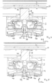
- the contacting device 1 with a contact assembly 4 is shown in longitudinal section in contact with a conductor 12 of a linear current guide in the embodiment according to Fig. 4 shown.
- the contact assembly 4 is inserted into the contact housing 2 of the contact device 1, with the central web 18 of the contact assembly 4 protruding through an opening 32 on the top of the contact housing 2 so that the contact element 20 can contact the conductor 12 running outside the contact device 1.
- the contact assembly 4 is freely and floatingly mounted in the contact device 1. This is achieved in that the contact device 1 comprises a receiving web 34 running in the transverse direction Q and the contact assembly 4 has a bearing recess 36 approximately in the area of the intersection of the central web 18 and the arms 22, which engages around the receiving web 34 when the contact assembly 4 is inserted into the contact device 1.
- the contacting device 1 comprises a leaf spring 38, which is arranged in the base area of the contacting housing 2 and below the contact assembly 4 and exerts a spring force on the contact assembly 4 in the direction of the conductors 12 of the linear current guide.
- the leaf spring 38 comprises two arms 40, which are formed in opposite directions in the longitudinal direction L and are supported at their arm ends on the base and the side walls of the contacting housing 1.
- the leaf spring 38 acts in its center on a formation 42 of the bearing recess 36 and presses the contact assembly 4 centrally and in the direction of the contacting direction K.
- the contact assembly 4 is mounted on the receiving web 34 in such a way that it can pivot around the axis of the receiving web. 34. This allows the contact element 20 or the contact blade to be guided along a partial area when the conductor is extended and moved in the longitudinal direction L, thereby minimizing frictional wear.
- Such a guiding and pivoting of the complete contact assembly 4 is possible in the embodiment according to the Figure 5 shown.
- the receiving web 34 is essentially circular in cross-section and the bearing recess 36 is adapted to this circular shape, so that the contact assembly 4 is mounted floating and freely on the receiving web 34.
- the possible pivoting range is defined by the width of the opening 32 on the top of the contact housing 2 or limited by this opening 32.
- the contacting device is specifically designed so that it can compensate for a change in length or displacement of the conductor by approximately 2 mm in both directions. This corresponds to a pivoting range of approximately 6° in both directions, i.e. a total pivoting range of approximately 12°. Within this pivoting range, the contact element 20 is always electrically connected to the conductor 12.
- the leaf spring 38 comprises a circular segment-shaped bulge 44 in its center, in which the formation 42 of the bearing recess 36 can roll during pivoting. This enables sufficient contact between the leaf spring 38 and the contact assembly 4 in every pivoting position.
- the pivot axis i.e. the receiving web 34, intersects the insertion axis of the external conductors, so that additional torque due to tensile forces is avoided as best as possible.
Landscapes
- Engineering & Computer Science (AREA)
- General Engineering & Computer Science (AREA)
- Coupling Device And Connection With Printed Circuit (AREA)
Claims (10)
- Système de mise en contact de conducteurs (12) avec un dispositif de mise en contact (1) et une pluralité de conducteurs (12) s'étendant dans la direction longitudinale (L), dans lequel le dispositif de mise en contact (1) comprend un boîtier de mise en contact (2), dans lequel une pluralité correspondante de modules de contact (4) est disposée, dans lequel chaque module de mise en contact (4) est affecté à un conducteur (12), dans lequel chaque module de contact (4) comprend un élément de contact (20), qui en l'état opérationnel vient en contact électrique avec le conducteur (12), caractérisé en ce que le module de contact (4) est positionné de manière pivotante dans une plage de pivotement, dans lequel l'axe de pivotement est configuré perpendiculairement à la direction longitudinale (L) dans la direction transversale (Q) et dans lequel le contact électrique est établi entre l'élément de contact (20) et le conducteur (12) sur essentiellement la totalité de la plage de pivotement.
- Système selon la revendication 1, caractérisé en ce que une pluralité de modules de contact (4) sont juxtaposés les uns aux autres dans la direction transversale (Q).
- Système selon la revendication 2, caractérisé en ce que chaque module de contact (4) est positionné de manière pivotante individuellement et indépendamment des autres autour de l'axe de pivotement.
- Système selon une des revendications 1 à 3, caractérisé en ce que dans le boîtier de mise en contact (2) un élément de ressort (38) est prévu pour chaque module de contact (4), afin de pouvoir fournir une pression de contact suffisante pour le contact électrique entre l'élément de contact (4) et le conducteur (12).
- Système selon une des revendications 1 à 4, caractérisé en ce que le boîtier de mise en contact (2) comprend un dispositif de pivotement.
- Système selon la revendication 5, caractérisé en ce que le dispositif de pivotement présente un gradin de réception (34) s'étendant dans la direction transversale (Q) et la pluralité de modules de contact (4) présentent respectivement un évidement (36), qui entoure au moins partiellement le gradin de réception (34) .
- Système selon une des revendications 1 à 6, caractérisé en ce que le boîtier de mise en contact (2) présente une pluralité d'ouvertures (32), à travers laquelle l'élément de contact (20) vient en prise avec un module de contact (4), dans lequel l'ouverture (32) est dimensionnée de telle sorte qu'elle définisse la plage de pivotement possible.
- Système selon une des revendications 1 à 7, caractérisé en ce que l'axe de pivotement est disposé dans la direction longitudinale (L) au centre par rapport au module de contact (4).
- Système selon une des revendications 1 à 8, caractérisé en ce que l'élément de contact (20) est configuré comme une lame de contact.
- Système selon une des revendications 1 à 9, caractérisé en ce que le module de contact (4) est configuré en forme de T, dans lequel le gradin médian (18) comprend l'élément de contact (20) et les bras (22) fournissent respectivement des ouvertures d'insertion (28) pour des conducteurs externes, dans lequel les deux ouvertures d'insertion (28) définissent une axe d'insertion, dans lequel l'axe de pivotement coupe en intersection l'axe d'introduction.
Applications Claiming Priority (1)
| Application Number | Priority Date | Filing Date | Title |
|---|---|---|---|
| DE102021133752.6A DE102021133752B3 (de) | 2021-12-17 | 2021-12-17 | System zur Kontaktierung von Leitern mit schwenkbaren Kontaktbaugruppen |
Publications (2)
| Publication Number | Publication Date |
|---|---|
| EP4199270A1 EP4199270A1 (fr) | 2023-06-21 |
| EP4199270B1 true EP4199270B1 (fr) | 2024-10-16 |
Family
ID=84537982
Family Applications (1)
| Application Number | Title | Priority Date | Filing Date |
|---|---|---|---|
| EP22214581.5A Active EP4199270B1 (fr) | 2021-12-17 | 2022-12-19 | Système de mise en contact de conducteurs avec des ensembles de contacts pivotants |
Country Status (4)
| Country | Link |
|---|---|
| EP (1) | EP4199270B1 (fr) |
| DE (1) | DE102021133752B3 (fr) |
| ES (1) | ES2998812T3 (fr) |
| PL (1) | PL4199270T3 (fr) |
Family Cites Families (2)
| Publication number | Priority date | Publication date | Assignee | Title |
|---|---|---|---|---|
| DE102017125270B3 (de) | 2017-10-27 | 2019-03-21 | Wago Verwaltungsgesellschaft Mbh | Abgriffsteckverbinder |
| DE102020100357A1 (de) | 2020-01-09 | 2021-07-15 | Wieland Electric Gmbh | Flachbandleitung als Stromführungsprofil |
-
2021
- 2021-12-17 DE DE102021133752.6A patent/DE102021133752B3/de active Active
-
2022
- 2022-12-19 EP EP22214581.5A patent/EP4199270B1/fr active Active
- 2022-12-19 ES ES22214581T patent/ES2998812T3/es active Active
- 2022-12-19 PL PL22214581.5T patent/PL4199270T3/pl unknown
Also Published As
| Publication number | Publication date |
|---|---|
| ES2998812T3 (en) | 2025-02-21 |
| PL4199270T3 (pl) | 2025-02-17 |
| EP4199270A1 (fr) | 2023-06-21 |
| DE102021133752B3 (de) | 2023-04-20 |
Similar Documents
| Publication | Publication Date | Title |
|---|---|---|
| EP3359412B1 (fr) | Système de charge rapide et procédé pour la liaison électrique d'un véhicule à un poste de charge | |
| EP3477774B1 (fr) | Connecteur du profilé d'alimentation en courant et dispositif d'alimentation en courant | |
| EP3765327B1 (fr) | Unité de contact | |
| DE102008039704A1 (de) | Kontaktanordnung mit gebogener Litze, Relais mit Kontaktanordnung und Verfahren zur Montage eines Relais | |
| WO2013004738A1 (fr) | Ensemble de serrage d'une borne de connexion électrique | |
| EP3477793A2 (fr) | Connecteur de dérivation | |
| EP4199270B1 (fr) | Système de mise en contact de conducteurs avec des ensembles de contacts pivotants | |
| WO2019185801A1 (fr) | Borne de conducteur | |
| DE102020100357A1 (de) | Flachbandleitung als Stromführungsprofil | |
| EP0254770B1 (fr) | Dispositif de contact électrique | |
| DE102020117240B4 (de) | Verbindungselement mit einem flexiblen Kontaktelement | |
| DE102020102487B4 (de) | Lineare Versorgungseinheit mit einer Pufferzone | |
| EP2337156A1 (fr) | Fiche de raccordement électrique | |
| EP3503312A1 (fr) | Profilé de guidage de courant | |
| EP4449563A1 (fr) | Luminaire modulaire à dispositif de contact | |
| EP3828025B1 (fr) | Borne de pré-contact pour une ligne de contact, aide à l'accès et système de ligne de contact | |
| EP4274044A1 (fr) | Système de guidage linéaire | |
| EP4199271B1 (fr) | Dispositif de retenue pour dispositifs de mise en contact | |
| DE102018127304B3 (de) | Stromabnehmer, Schleifleitung und Schleifleitungssystem | |
| EP3940894B1 (fr) | Élément de fixation pour le contact pe | |
| DE102020102491B4 (de) | Lineare Stromverteileranordnung mit einem an einer linearen Versorgungseinheit angeordneten Abgriff | |
| EP4042526A1 (fr) | Barre omnibus destinée à des lampes ou des unités électriques | |
| EP3876356A1 (fr) | Agencement des composants destiné à la transmission du courant électrique | |
| EP1587173B1 (fr) | Dispositif pour la connexion électrique d'un dispositif d'alimentation électrique à un dispositif de consommation électrique | |
| DE102019132567A1 (de) | Stromabnehmer und Schleifleitungssystem |
Legal Events
| Date | Code | Title | Description |
|---|---|---|---|
| PUAI | Public reference made under article 153(3) epc to a published international application that has entered the european phase |
Free format text: ORIGINAL CODE: 0009012 |
|
| STAA | Information on the status of an ep patent application or granted ep patent |
Free format text: STATUS: THE APPLICATION HAS BEEN PUBLISHED |
|
| AK | Designated contracting states |
Kind code of ref document: A1 Designated state(s): AL AT BE BG CH CY CZ DE DK EE ES FI FR GB GR HR HU IE IS IT LI LT LU LV MC ME MK MT NL NO PL PT RO RS SE SI SK SM TR |
|
| STAA | Information on the status of an ep patent application or granted ep patent |
Free format text: STATUS: REQUEST FOR EXAMINATION WAS MADE |
|
| 17P | Request for examination filed |
Effective date: 20231220 |
|
| RBV | Designated contracting states (corrected) |
Designated state(s): AL AT BE BG CH CY CZ DE DK EE ES FI FR GB GR HR HU IE IS IT LI LT LU LV MC ME MK MT NL NO PL PT RO RS SE SI SK SM TR |
|
| REG | Reference to a national code |
Ref country code: DE Ref legal event code: R079 Ipc: F21V0021350000 Ref country code: DE Ref legal event code: R079 Ref document number: 502022001917 Country of ref document: DE Free format text: PREVIOUS MAIN CLASS: H01R0025140000 Ipc: F21V0021350000 |
|
| GRAP | Despatch of communication of intention to grant a patent |
Free format text: ORIGINAL CODE: EPIDOSNIGR1 |
|
| STAA | Information on the status of an ep patent application or granted ep patent |
Free format text: STATUS: GRANT OF PATENT IS INTENDED |
|
| RIC1 | Information provided on ipc code assigned before grant |
Ipc: H01R 13/631 20060101ALI20240418BHEP Ipc: H01R 4/48 20060101ALI20240418BHEP Ipc: H01R 25/14 20060101ALI20240418BHEP Ipc: F21V 21/35 20060101AFI20240418BHEP |
|
| INTG | Intention to grant announced |
Effective date: 20240506 |
|
| GRAS | Grant fee paid |
Free format text: ORIGINAL CODE: EPIDOSNIGR3 |
|
| GRAA | (expected) grant |
Free format text: ORIGINAL CODE: 0009210 |
|
| STAA | Information on the status of an ep patent application or granted ep patent |
Free format text: STATUS: THE PATENT HAS BEEN GRANTED |
|
| AK | Designated contracting states |
Kind code of ref document: B1 Designated state(s): AL AT BE BG CH CY CZ DE DK EE ES FI FR GB GR HR HU IE IS IT LI LT LU LV MC ME MK MT NL NO PL PT RO RS SE SI SK SM TR |
|
| REG | Reference to a national code |
Ref country code: GB Ref legal event code: FG4D Free format text: NOT ENGLISH |
|
| REG | Reference to a national code |
Ref country code: CH Ref legal event code: EP |
|
| REG | Reference to a national code |
Ref country code: IE Ref legal event code: FG4D Free format text: LANGUAGE OF EP DOCUMENT: GERMAN |
|
| REG | Reference to a national code |
Ref country code: DE Ref legal event code: R096 Ref document number: 502022001917 Country of ref document: DE |
|
| REG | Reference to a national code |
Ref country code: SE Ref legal event code: TRGR |
|
| REG | Reference to a national code |
Ref country code: LT Ref legal event code: MG9D |
|
| REG | Reference to a national code |
Ref country code: NL Ref legal event code: MP Effective date: 20241016 |
|
| REG | Reference to a national code |
Ref country code: ES Ref legal event code: FG2A Ref document number: 2998812 Country of ref document: ES Kind code of ref document: T3 Effective date: 20250221 |
|
| PG25 | Lapsed in a contracting state [announced via postgrant information from national office to epo] |
Ref country code: NL Free format text: LAPSE BECAUSE OF FAILURE TO SUBMIT A TRANSLATION OF THE DESCRIPTION OR TO PAY THE FEE WITHIN THE PRESCRIBED TIME-LIMIT Effective date: 20241016 |
|
| PG25 | Lapsed in a contracting state [announced via postgrant information from national office to epo] |
Ref country code: NL Free format text: LAPSE BECAUSE OF FAILURE TO SUBMIT A TRANSLATION OF THE DESCRIPTION OR TO PAY THE FEE WITHIN THE PRESCRIBED TIME-LIMIT Effective date: 20241016 |
|
| PG25 | Lapsed in a contracting state [announced via postgrant information from national office to epo] |
Ref country code: IS Free format text: LAPSE BECAUSE OF FAILURE TO SUBMIT A TRANSLATION OF THE DESCRIPTION OR TO PAY THE FEE WITHIN THE PRESCRIBED TIME-LIMIT Effective date: 20250216 Ref country code: HR Free format text: LAPSE BECAUSE OF FAILURE TO SUBMIT A TRANSLATION OF THE DESCRIPTION OR TO PAY THE FEE WITHIN THE PRESCRIBED TIME-LIMIT Effective date: 20241016 Ref country code: PT Free format text: LAPSE BECAUSE OF FAILURE TO SUBMIT A TRANSLATION OF THE DESCRIPTION OR TO PAY THE FEE WITHIN THE PRESCRIBED TIME-LIMIT Effective date: 20250217 |
|
| PG25 | Lapsed in a contracting state [announced via postgrant information from national office to epo] |
Ref country code: FI Free format text: LAPSE BECAUSE OF FAILURE TO SUBMIT A TRANSLATION OF THE DESCRIPTION OR TO PAY THE FEE WITHIN THE PRESCRIBED TIME-LIMIT Effective date: 20241016 |
|
| PG25 | Lapsed in a contracting state [announced via postgrant information from national office to epo] |
Ref country code: BG Free format text: LAPSE BECAUSE OF FAILURE TO SUBMIT A TRANSLATION OF THE DESCRIPTION OR TO PAY THE FEE WITHIN THE PRESCRIBED TIME-LIMIT Effective date: 20241016 |
|
| PG25 | Lapsed in a contracting state [announced via postgrant information from national office to epo] |
Ref country code: NO Free format text: LAPSE BECAUSE OF FAILURE TO SUBMIT A TRANSLATION OF THE DESCRIPTION OR TO PAY THE FEE WITHIN THE PRESCRIBED TIME-LIMIT Effective date: 20250116 |
|
| PG25 | Lapsed in a contracting state [announced via postgrant information from national office to epo] |
Ref country code: LV Free format text: LAPSE BECAUSE OF FAILURE TO SUBMIT A TRANSLATION OF THE DESCRIPTION OR TO PAY THE FEE WITHIN THE PRESCRIBED TIME-LIMIT Effective date: 20241016 Ref country code: GR Free format text: LAPSE BECAUSE OF FAILURE TO SUBMIT A TRANSLATION OF THE DESCRIPTION OR TO PAY THE FEE WITHIN THE PRESCRIBED TIME-LIMIT Effective date: 20250117 |
|
| PG25 | Lapsed in a contracting state [announced via postgrant information from national office to epo] |
Ref country code: IT Free format text: LAPSE BECAUSE OF NON-PAYMENT OF DUE FEES Effective date: 20241219 |
|
| PG25 | Lapsed in a contracting state [announced via postgrant information from national office to epo] |
Ref country code: RS Free format text: LAPSE BECAUSE OF FAILURE TO SUBMIT A TRANSLATION OF THE DESCRIPTION OR TO PAY THE FEE WITHIN THE PRESCRIBED TIME-LIMIT Effective date: 20250116 |
|
| PG25 | Lapsed in a contracting state [announced via postgrant information from national office to epo] |
Ref country code: SM Free format text: LAPSE BECAUSE OF FAILURE TO SUBMIT A TRANSLATION OF THE DESCRIPTION OR TO PAY THE FEE WITHIN THE PRESCRIBED TIME-LIMIT Effective date: 20241016 |
|
| PG25 | Lapsed in a contracting state [announced via postgrant information from national office to epo] |
Ref country code: MC Free format text: LAPSE BECAUSE OF FAILURE TO SUBMIT A TRANSLATION OF THE DESCRIPTION OR TO PAY THE FEE WITHIN THE PRESCRIBED TIME-LIMIT Effective date: 20241016 |
|
| PG25 | Lapsed in a contracting state [announced via postgrant information from national office to epo] |
Ref country code: DK Free format text: LAPSE BECAUSE OF FAILURE TO SUBMIT A TRANSLATION OF THE DESCRIPTION OR TO PAY THE FEE WITHIN THE PRESCRIBED TIME-LIMIT Effective date: 20241016 |
|
| REG | Reference to a national code |
Ref country code: DE Ref legal event code: R097 Ref document number: 502022001917 Country of ref document: DE |
|
| PG25 | Lapsed in a contracting state [announced via postgrant information from national office to epo] |
Ref country code: EE Free format text: LAPSE BECAUSE OF FAILURE TO SUBMIT A TRANSLATION OF THE DESCRIPTION OR TO PAY THE FEE WITHIN THE PRESCRIBED TIME-LIMIT Effective date: 20241016 |
|
| PG25 | Lapsed in a contracting state [announced via postgrant information from national office to epo] |
Ref country code: RO Free format text: LAPSE BECAUSE OF FAILURE TO SUBMIT A TRANSLATION OF THE DESCRIPTION OR TO PAY THE FEE WITHIN THE PRESCRIBED TIME-LIMIT Effective date: 20241016 |
|
| PG25 | Lapsed in a contracting state [announced via postgrant information from national office to epo] |
Ref country code: SK Free format text: LAPSE BECAUSE OF FAILURE TO SUBMIT A TRANSLATION OF THE DESCRIPTION OR TO PAY THE FEE WITHIN THE PRESCRIBED TIME-LIMIT Effective date: 20241016 |
|
| PG25 | Lapsed in a contracting state [announced via postgrant information from national office to epo] |
Ref country code: CZ Free format text: LAPSE BECAUSE OF FAILURE TO SUBMIT A TRANSLATION OF THE DESCRIPTION OR TO PAY THE FEE WITHIN THE PRESCRIBED TIME-LIMIT Effective date: 20241016 |
|
| PG25 | Lapsed in a contracting state [announced via postgrant information from national office to epo] |
Ref country code: LU Free format text: LAPSE BECAUSE OF NON-PAYMENT OF DUE FEES Effective date: 20241219 |
|
| PLBE | No opposition filed within time limit |
Free format text: ORIGINAL CODE: 0009261 |
|
| STAA | Information on the status of an ep patent application or granted ep patent |
Free format text: STATUS: NO OPPOSITION FILED WITHIN TIME LIMIT |
|
| 26N | No opposition filed |
Effective date: 20250717 |
|
| REG | Reference to a national code |
Ref country code: BE Ref legal event code: MM Effective date: 20241231 |
|
| PG25 | Lapsed in a contracting state [announced via postgrant information from national office to epo] |
Ref country code: BE Free format text: LAPSE BECAUSE OF NON-PAYMENT OF DUE FEES Effective date: 20241231 |
|
| PG25 | Lapsed in a contracting state [announced via postgrant information from national office to epo] |
Ref country code: IE Free format text: LAPSE BECAUSE OF NON-PAYMENT OF DUE FEES Effective date: 20241219 |
|
| PGFP | Annual fee paid to national office [announced via postgrant information from national office to epo] |
Ref country code: AT Payment date: 20260113 Year of fee payment: 4 |
|
| PG25 | Lapsed in a contracting state [announced via postgrant information from national office to epo] |
Ref country code: IT Free format text: LAPSE BECAUSE OF NON-PAYMENT OF DUE FEES Effective date: 20241219 |
|
| PGRI | Patent reinstated in contracting state [announced from national office to epo] |
Ref country code: IT Effective date: 20241231 |
|
| PGFP | Annual fee paid to national office [announced via postgrant information from national office to epo] |
Ref country code: FR Payment date: 20251218 Year of fee payment: 4 |
|
| PGFP | Annual fee paid to national office [announced via postgrant information from national office to epo] |
Ref country code: TR Payment date: 20251215 Year of fee payment: 4 |
|
| PGFP | Annual fee paid to national office [announced via postgrant information from national office to epo] |
Ref country code: SE Payment date: 20251217 Year of fee payment: 4 |
|
| PGFP | Annual fee paid to national office [announced via postgrant information from national office to epo] |
Ref country code: PL Payment date: 20251209 Year of fee payment: 4 |
|
| PGFP | Annual fee paid to national office [announced via postgrant information from national office to epo] |
Ref country code: ES Payment date: 20260119 Year of fee payment: 4 |
|
| PGFP | Annual fee paid to national office [announced via postgrant information from national office to epo] |
Ref country code: DE Payment date: 20251222 Year of fee payment: 4 |
|
| PGFP | Annual fee paid to national office [announced via postgrant information from national office to epo] |
Ref country code: IT Payment date: 20251231 Year of fee payment: 4 |