EP4199270B1 - System zur kontaktierung von leitern mit schwenkbaren kontaktbaugruppen - Google Patents
System zur kontaktierung von leitern mit schwenkbaren kontaktbaugruppen Download PDFInfo
- Publication number
- EP4199270B1 EP4199270B1 EP22214581.5A EP22214581A EP4199270B1 EP 4199270 B1 EP4199270 B1 EP 4199270B1 EP 22214581 A EP22214581 A EP 22214581A EP 4199270 B1 EP4199270 B1 EP 4199270B1
- Authority
- EP
- European Patent Office
- Prior art keywords
- contact
- conductors
- assembly
- contact assembly
- conductor
- Prior art date
- Legal status (The legal status is an assumption and is not a legal conclusion. Google has not performed a legal analysis and makes no representation as to the accuracy of the status listed.)
- Active
Links
Images


Classifications
-
- H—ELECTRICITY
- H01—ELECTRIC ELEMENTS
- H01R—ELECTRICALLY-CONDUCTIVE CONNECTIONS; STRUCTURAL ASSOCIATIONS OF A PLURALITY OF MUTUALLY-INSULATED ELECTRICAL CONNECTING ELEMENTS; COUPLING DEVICES; CURRENT COLLECTORS
- H01R25/00—Coupling parts adapted for simultaneous co-operation with two or more identical counterparts, e.g. for distributing energy to two or more circuits
- H01R25/14—Rails or bus-bars constructed so that the counterparts can be connected thereto at any point along their length
- H01R25/142—Their counterparts
-
- F—MECHANICAL ENGINEERING; LIGHTING; HEATING; WEAPONS; BLASTING
- F21—LIGHTING
- F21V—FUNCTIONAL FEATURES OR DETAILS OF LIGHTING DEVICES OR SYSTEMS THEREOF; STRUCTURAL COMBINATIONS OF LIGHTING DEVICES WITH OTHER ARTICLES, NOT OTHERWISE PROVIDED FOR
- F21V21/00—Supporting, suspending, or attaching arrangements for lighting devices; Hand grips
- F21V21/34—Supporting elements displaceable along a guiding element
- F21V21/35—Supporting elements displaceable along a guiding element with direct electrical contact between the supporting element and electric conductors running along the guiding element
-
- H—ELECTRICITY
- H01—ELECTRIC ELEMENTS
- H01R—ELECTRICALLY-CONDUCTIVE CONNECTIONS; STRUCTURAL ASSOCIATIONS OF A PLURALITY OF MUTUALLY-INSULATED ELECTRICAL CONNECTING ELEMENTS; COUPLING DEVICES; CURRENT COLLECTORS
- H01R13/00—Details of coupling devices of the kinds covered by groups H01R12/70 or H01R24/00 - H01R33/00
- H01R13/62—Means for facilitating engagement or disengagement of coupling parts or for holding them in engagement
- H01R13/629—Additional means for facilitating engagement or disengagement of coupling parts, e.g. aligning or guiding means, levers, gas pressure electrical locking indicators, manufacturing tolerances
- H01R13/631—Additional means for facilitating engagement or disengagement of coupling parts, e.g. aligning or guiding means, levers, gas pressure electrical locking indicators, manufacturing tolerances for engagement only
- H01R13/6315—Additional means for facilitating engagement or disengagement of coupling parts, e.g. aligning or guiding means, levers, gas pressure electrical locking indicators, manufacturing tolerances for engagement only allowing relative movement between coupling parts, e.g. floating connection
-
- H—ELECTRICITY
- H01—ELECTRIC ELEMENTS
- H01R—ELECTRICALLY-CONDUCTIVE CONNECTIONS; STRUCTURAL ASSOCIATIONS OF A PLURALITY OF MUTUALLY-INSULATED ELECTRICAL CONNECTING ELEMENTS; COUPLING DEVICES; CURRENT COLLECTORS
- H01R4/00—Electrically-conductive connections between two or more conductive members in direct contact, i.e. touching one another; Means for effecting or maintaining such contact; Electrically-conductive connections having two or more spaced connecting locations for conductors and using contact members penetrating insulation
- H01R4/28—Clamped connections, spring connections
- H01R4/48—Clamped connections, spring connections utilising a spring, clip, or other resilient member
- H01R4/4809—Clamped connections, spring connections utilising a spring, clip, or other resilient member using a leaf spring to bias the conductor toward the busbar
- H01R4/48185—Clamped connections, spring connections utilising a spring, clip, or other resilient member using a leaf spring to bias the conductor toward the busbar adapted for axial insertion of a wire end
- H01R4/4819—Clamped connections, spring connections utilising a spring, clip, or other resilient member using a leaf spring to bias the conductor toward the busbar adapted for axial insertion of a wire end the spring shape allowing insertion of the conductor end when the spring is unbiased
- H01R4/4821—Single-blade spring
-
- H—ELECTRICITY
- H01—ELECTRIC ELEMENTS
- H01R—ELECTRICALLY-CONDUCTIVE CONNECTIONS; STRUCTURAL ASSOCIATIONS OF A PLURALITY OF MUTUALLY-INSULATED ELECTRICAL CONNECTING ELEMENTS; COUPLING DEVICES; CURRENT COLLECTORS
- H01R4/00—Electrically-conductive connections between two or more conductive members in direct contact, i.e. touching one another; Means for effecting or maintaining such contact; Electrically-conductive connections having two or more spaced connecting locations for conductors and using contact members penetrating insulation
- H01R4/28—Clamped connections, spring connections
- H01R4/48—Clamped connections, spring connections utilising a spring, clip, or other resilient member
- H01R4/4809—Clamped connections, spring connections utilising a spring, clip, or other resilient member using a leaf spring to bias the conductor toward the busbar
- H01R4/4828—Spring-activating arrangements mounted on or integrally formed with the spring housing
- H01R4/4833—Sliding arrangements, e.g. sliding button
-
- H—ELECTRICITY
- H01—ELECTRIC ELEMENTS
- H01R—ELECTRICALLY-CONDUCTIVE CONNECTIONS; STRUCTURAL ASSOCIATIONS OF A PLURALITY OF MUTUALLY-INSULATED ELECTRICAL CONNECTING ELEMENTS; COUPLING DEVICES; CURRENT COLLECTORS
- H01R4/00—Electrically-conductive connections between two or more conductive members in direct contact, i.e. touching one another; Means for effecting or maintaining such contact; Electrically-conductive connections having two or more spaced connecting locations for conductors and using contact members penetrating insulation
- H01R4/28—Clamped connections, spring connections
- H01R4/48—Clamped connections, spring connections utilising a spring, clip, or other resilient member
- H01R4/4809—Clamped connections, spring connections utilising a spring, clip, or other resilient member using a leaf spring to bias the conductor toward the busbar
- H01R4/4846—Busbar details
- H01R4/485—Single busbar common to multiple springs
Definitions
- the invention relates to a system for contacting conductors with a contacting device and a number of conductors extending in the longitudinal direction, wherein the contacting device comprises a contacting housing in which a corresponding number of contact assemblies are arranged, wherein each contact assembly is assigned to a conductor, wherein each contact assembly comprises a contact element which comes into electrical contact with the conductor in the operating state, wherein the contact assembly is pivotally mounted in a pivoting range and wherein the pivot axis is formed perpendicular to the longitudinal direction in the transverse direction.
- Such systems generally relate to linear power distribution arrangements, which are used in particular for lighting systems in buildings in order to lay cables for supplying devices with energy and/or signals in a cost-effective and visually appealing manner.
- Signals are understood to mean both the transmission of general signals, such as control signals, and the transmission of data, such as measurement or information data.
- the installation location of the devices can be flexibly selected along a housing body of the power distribution arrangement and can be easily varied. The devices can thus be easily contacted with a contacting element in an electrically conductive manner with the conductors of a linear supply unit at a variably definable installation location.
- Such power distribution arrangements have the advantage that the devices are both electrically contacted and mechanically supported on the housing body.
- the contacting devices within the meaning of these applications include both feeders and assemblies that feed the corresponding signals and/or energy into the conductors to be contacted, but also taps that feed the corresponding Capture signals and/or energy from the contacting conductors and supply them to external devices.
- DE 10 2017 125270 B3 and DE 10 2020 100357 A1 disclose examples of such contacting devices.
- linear power distribution arrangements usually use linear supply units that are housed in a housing body. These supply units can be designed as power guide profiles or as ribbon cables, for example.
- the power guide profiles are made from a base body that extends in the longitudinal direction and has a number of chambers in which individual conductors are arranged. These power guide profiles are usually rigid and have a limited length due to the manufacturing process. For longer power distribution arrangements, such as those used in larger factories or warehouses, several power guide profiles are therefore usually required, which are then connected to one another both mechanically and electrically via a connecting element.
- connecting elements can also be used depending on the length of the ribbon cable.
- Rigid round conductors are usually used as conductors, which are inserted or placed into the chambers.
- a contacting device with a number of contact elements which acts as a tap, then reaches into these chambers and contacts the contact elements with the corresponding conductors, whereby the signals or energy can be passed from the conductors to the end devices via the taps.
- the reverse is also true for corresponding feeders.
- the problem with this type of design is that due to the length of the linear systems, they are very susceptible to external thermal influences. This leads to a change in the length of the conductors or to a displacement of the conductors within the chambers in the longitudinal direction.
- the object of the invention is in particular to provide a contacting device which has a particularly low wear in the area of the contact zones with the conductors in the event of thermal length changes of the conductors and is therefore particularly durable and has a particularly good contact.
- the invention is based on the idea that particularly low wear is possible, in particular, when the relative movement between the two contact surfaces is kept small. This can be achieved in particular when the contact element or the contact assembly follows the change in length of the conductors due to external thermal fluctuations and does not remain rigidly in one position. Since a complete, in particular linear displacement of the contacting device to compensate for the change in length of the conductors is not possible or only shifts the problem due to the fixation in receiving units, such as support profiles, or due to the additional connections to the contacting device, the invention takes the approach that the individual contact assemblies compensate for the change in length individually and independently of one another. To avoid possible tensile forces on the external conductors connected to the contact assemblies in the event of a linear displacement of the contact assemblies, this displacement is dispensed with and the contact elements are adjusted by pivoting or rotating around a pivot axis.
- the contacting device In order to contact a linear power supply with a linear current-carrying profile and a plurality of conductors arranged parallel to one another, the contacting device preferably has a plurality of contact assemblies which are arranged one behind the other in the transverse direction, i.e. in accordance with the arrangement of the associated conductors. Even if in principle a coupling of several contact assemblies to form an assembly unit is possible and in individual cases could also be preferably implemented, in an advantageous embodiment each of these contact assemblies is mounted individually and independently of each other so that it can pivot about the pivot axis, so that different expansions and displacements of individual conductors can also be tracked.
- this contact force is provided by a spring element, in particular a leaf spring.
- This spring element can be arranged in the contact housing of the contacting device so that it moves the entire contact assembly in the direction of the conductors. It is particularly advantageous if the leaf spring is arranged stationary in the contact housing and does not follow the pivoting movement of the contact assembly, but is nevertheless designed such that the contact force is sufficiently high over the entire pivoting range.
- the leaf spring advantageously comprises a circular segment-shaped effective range in which the contact assembly rolls during the pivoting movement and is always subjected to a sufficiently high spring force.
- the spring element can also be arranged in the contact housing so that it follows the pivoting movement.
- the contact housing comprises a pivoting device which, in an advantageous embodiment, comprises a receiving web running in the transverse direction.
- the contact assembly comprises a corresponding, essentially U-shaped bearing recess in the lower area, with which the contact assembly is placed on the receiving web.
- the bearing recess at least partially surrounds the receiving web and is arranged pivotably on it, with the receiving web defining the pivot axis.
- the contact assemblies are essentially T-shaped, with the central web enclosing the contact element and the arms providing connection options for external conductors in order to be able to connect terminal devices to the contacting device.
- the bearing recess is advantageously arranged at the intersection point of the central web and the arms.
- insertion openings are provided on both sides of the arms, which together form an insertion opening.
- the pivot axis intersects the insertion axis in an advantageous embodiment. This avoids additional torques due to the tensile forces and thus a rotational movement of the contacting device.
- the contact element passes through an opening in the contact housing.
- This opening is wider in the longitudinal direction than the contact element, which allows it to pivot within the opening.
- the pivoting range is therefore defined by the width of the opening in the longitudinal direction and can be adjusted so that, on the one hand, sufficient contact pressure can be provided over the entire pivoting range and, on the other hand, common or expected length expansions of the conductors can be compensated.
- the electrical contact over the entire pivoting range can be provided in a preferred manner in particular because the contact surface is widened in the longitudinal direction.
- the contact element is thus designed as a contact blade.
- each individual contact assembly makes it possible to react to changes in the length of the conductors or displacements of the conductors due to external thermal influences, so that a particularly small relative movement occurs between the conductor and the contact element. This leads to particularly low wear and enables a particularly long-lasting and secure electrical contact of the conductors.
- the contacting device 1 comprises a contacting housing 2 in which a number of contact assemblies 4 are arranged.
- the contact assemblies 4 are arranged one behind the other in the transverse direction Q and are individually stored in the contacting housing 2.
- the contacting device 1 also comprises a holding device 6 which, in the embodiment shown here, is arranged laterally, i.e. in front of and behind the contact assemblies 4 in the transverse direction, and enables the contacting device 1 to be fixed in a corresponding receptacle, for example in a support profile.
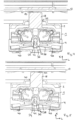
- FIG. 2 An exemplary receptacle of a contacting device 1 in a support profile 8 is shown in Figure 2 shown in cross-section.
- the support profile 8 comprises a linear current guide, which consists of a comb-like current guide profile 10, with a conductor 12 inserted in each chamber.
- the contact assemblies 4 in the contacting device 1 are arranged next to one another at a distance such that each contact assembly 4 is assigned a conductor 12 and thus each Contact assembly 4 can contact a conductor 12.
- the contacting device 1 comprises a holding device 6 which is arranged on two lateral and opposite walls. This holding device essentially comprises a number of holding clips 14 which engage in corresponding undercuts 16 of the support profile and fix the contacting device 1 there.
- a contact assembly 4 of the contacting device 1 is in the embodiment according to the Figure 3 shown in more detail.
- the contact assembly 4 is essentially T-shaped, with the central web 18 of the contact assembly 4 enclosing the contact element 20 and the arms 22 of the contact assembly 4 being designed to receive conductors for external connecting conductors.
- the contact assembly 4 is oriented or inserted into the contacting device 1 in such a way that the arms 22 are formed in the longitudinal direction L and thus parallel to the conductors 12 to be contacted and the central web 18 is oriented perpendicular to the longitudinal direction L and transverse direction Q in the contacting direction K.
- the contact element 20 is in the embodiment according to Figure 3 designed as a contact blade with a longitudinally flat and wide contact surface for contacting the conductors 12, for example the conductor 12 of the linear current guide from the embodiment according to Fig. 2
- the contact surface is made of a conductive material 24 that extends along the central web to the arms 22 of the contact assembly 4.
- the central web 18 itself is widened by means of an insulating material 26, whereby air and creepage distances can be maintained.
- the arms 22 of the contact assembly 4 essentially each comprise a receptacle for connecting external conductors, which are to be connected to the conductors 12 of the linear current guide via the contact assembly 4.
- the arms 22 each comprise an insertion opening 28 on their front sides through which the external conductors can be inserted.
- These external conductors are pressed onto the conductive material 24 of the contact element 4 in the interior area via a leg spring 30 and are thus fixed there.
- the insertion openings 28 for the external Conductors are arranged on both sides of the arms 22 and are in a line. They thus form an insertion axis for the external conductors.
- the contacting device 1 with a contact assembly 4 is shown in longitudinal section in contact with a conductor 12 of a linear current guide in the embodiment according to Fig. 4 shown.
- the contact assembly 4 is inserted into the contact housing 2 of the contact device 1, with the central web 18 of the contact assembly 4 protruding through an opening 32 on the top of the contact housing 2 so that the contact element 20 can contact the conductor 12 running outside the contact device 1.
- the contact assembly 4 is freely and floatingly mounted in the contact device 1. This is achieved in that the contact device 1 comprises a receiving web 34 running in the transverse direction Q and the contact assembly 4 has a bearing recess 36 approximately in the area of the intersection of the central web 18 and the arms 22, which engages around the receiving web 34 when the contact assembly 4 is inserted into the contact device 1.
- the contacting device 1 comprises a leaf spring 38, which is arranged in the base area of the contacting housing 2 and below the contact assembly 4 and exerts a spring force on the contact assembly 4 in the direction of the conductors 12 of the linear current guide.
- the leaf spring 38 comprises two arms 40, which are formed in opposite directions in the longitudinal direction L and are supported at their arm ends on the base and the side walls of the contacting housing 1.
- the leaf spring 38 acts in its center on a formation 42 of the bearing recess 36 and presses the contact assembly 4 centrally and in the direction of the contacting direction K.
- the contact assembly 4 is mounted on the receiving web 34 in such a way that it can pivot around the axis of the receiving web. 34. This allows the contact element 20 or the contact blade to be guided along a partial area when the conductor is extended and moved in the longitudinal direction L, thereby minimizing frictional wear.
- Such a guiding and pivoting of the complete contact assembly 4 is possible in the embodiment according to the Figure 5 shown.
- the receiving web 34 is essentially circular in cross-section and the bearing recess 36 is adapted to this circular shape, so that the contact assembly 4 is mounted floating and freely on the receiving web 34.
- the possible pivoting range is defined by the width of the opening 32 on the top of the contact housing 2 or limited by this opening 32.
- the contacting device is specifically designed so that it can compensate for a change in length or displacement of the conductor by approximately 2 mm in both directions. This corresponds to a pivoting range of approximately 6° in both directions, i.e. a total pivoting range of approximately 12°. Within this pivoting range, the contact element 20 is always electrically connected to the conductor 12.
- the leaf spring 38 comprises a circular segment-shaped bulge 44 in its center, in which the formation 42 of the bearing recess 36 can roll during pivoting. This enables sufficient contact between the leaf spring 38 and the contact assembly 4 in every pivoting position.
- the pivot axis i.e. the receiving web 34, intersects the insertion axis of the external conductors, so that additional torque due to tensile forces is avoided as best as possible.
Landscapes
- Engineering & Computer Science (AREA)
- General Engineering & Computer Science (AREA)
- Coupling Device And Connection With Printed Circuit (AREA)
Description
- Die Erfindung betrifft ein System zur Kontaktierung von Leitern mit einer Kontaktierungsvorrichtung und einer Anzahl sich in Längsrichtung erstreckender Leiter, wobei die Kontaktierungsvorrichtung ein Kontaktierungsgehäuse umfasst, in das eine entsprechenden Anzahl von Kontaktbaugruppen angeordnet ist, wobei jede Kontaktbaugruppe einem Leiter zugeordnet ist, wobei jede Kontaktbaugruppe ein Kontaktelement umfasst, welches im Betriebszustand in einen elektrischen Kontakt mit dem Leiter tritt, wobei die Kontaktbaugruppe in einem Schwenkbereich schwenkbar gelagert ist und wobei die Schwenkachse senkrecht zur Längsrichtung in Querrichtung ausgebildet ist.
- Derartige System betreffen in der Regel lineare Stromverteileranordnungen, die insbesondere für Beleuchtungssysteme in Gebäuden eingesetzt werden, um Leitungen zur Versorgung von Geräten mit Energie und/oder Signalen kostengünstig und optisch ansprechend zu verlegen. Unter Signalen wird dabei sowohl die Übertragung von allgemeinen Signalen, wie beispielsweise Steuersignalen, als auch die Übertragung von Daten, wie beispielsweise Mess- oder Informationsdaten, verstanden. Der Einbauort der Geräte kann flexibel entlang eines Gehäusekörpers der Stromverteileranordnung gewählt und leicht variiert werden. Die Geräte können damit auf einfache Weise mit einem Kontaktierungselement elektrisch leitend mit den Leitern einer linearen Versorgungseinheit an einem variabel festlegbaren Einbauort kontaktiert werden. Solche Stromverteileranordnungen haben den Vorteil, dass die Geräte sowohl elektrisch kontaktierend und auch zu gleich mechanisch an dem Gehäusekörper getragen werden.
- Die Kontaktierungsvorrichtungen im Sinne dieser Anmeldungen umfassen dabei sowohl Einspeiser, als Baugruppen, die entsprechende Signale und/oder Energie in die zu kontaktierenden Leiter einspeisen, aber ebenso Abgriffe, die die entsprechenden Signale und/oder Energie aus den kontaktierenden Leitern abgreifen und externen Endgeräten zuführen.
DE 10 2017 125270 B3 undDE 10 2020 100357 A1 offenbaren Beispiele für solche Kontaktierungsvorrichtungen. - Zur Verteilung bzw. Weiterleitung der Energie oder Signale werden in den linearen Stromverteileranordnungen meist lineare Versorgungseinheiten verwendet, die in einem Gehäusekörper gelagert werden. Diese Versorgungseinheiten können dabei beispielsweise als Stromführungsprofile aber auch als Flachbandkabel ausgebildet sein. Die Stromführungsprofile sind aus einem sich in Längsrichtung erstreckenden Grundkörper ausgebildet, der eine Anzahl von Kammern aufweist, in denen einzelne Leiter angeordnet sind. Diese Stromführungsprofile sind in der Regel starr ausgebildet und weisen herstellungsbedingt eine begrenzte Länge auf. Für längere Stromverteileranordnungen, wie sie beispielsweise in größeren Werks- oder Lagerhallen eingesetzt werden, sind daher üblicherweise mehrere Stromführungsprofile nötig, die dann über ein Verbindungselement sowohl mechanisch als auch elektrisch miteinander verbunden werden. Auch bei der Verwendung von Flachbandkabeln können je nach Länge des Flachbandkabels Verbindungselemente eingesetzt werden.
- Als Leiter werden üblicherweise starre Rundleiter verwendet, die in die Kammern eingesetzt oder eingelegt werden. Eine Kontaktierungsvorrichtung mit einer Anzahl von Kontaktelementen, die als Abgriff fungiert, greift dann in diese Kammern ein und kontaktiert die Kontaktelemente mit den entsprechenden Leitern, wodurch die Signale oder die Energie von den Leitern über die Abgriffe an die Endgeräte geleitet werden können. Umgekehrt ist dies auch für entsprechende Einspeiser gültig. Problematisch bei dieser Art der Ausgestaltung ist allerdings, dass aufgrund der Länge der linearen Systeme, diese sehr anfällig für äußere thermische Einflüsse sind. Dies führt zu einer Längenveränderung der Leiter bzw. zu einer Verschiebung der Leiter innerhalb der Kammern in Längsrichtung.
- Eine derartige Verschiebung der Leiter führt zu einer Reibbelastung der Kontaktflächen zwischen den Kontaktelementen und den Leitern und damit zum Abrieb Verschleiß der Kontaktflächen. Dies kann langfristig die elektrische Kontaktierung beeinträchtigen oder gar ganz unterbrechen.
- Die Aufgabe der Erfindung besteht insbesondere darin eine Kontaktierungsvorrichtung anzugeben, die einen besonders geringen Verschleiß im Bereich der Kontaktzonen mit den Leitern bei thermischen Längenänderungen der Leiter aufweist und daher besonders langlebig ist und eine besonders gute Kontaktierung aufweist.
- Die Aufgabe wird erfindungsgemäß durch die kennzeichnenden Merkmale der unabhängigen Ansprüche gelöst.
- Die Erfindung geht von der Überlegung aus, dass ein besonders geringer Verschleiß insbesondere dann möglich ist, wenn die Relativbewegung zwischen den beiden Kontaktflächen gering gehalten wird. Dies kann insbesondere dann erreicht werden, wenn das Kontaktelement bzw. die Kontaktbaugruppe die Längenänderung der Leiter aufgrund von äußeren thermischen Schwankungen mitgeht und nicht starr in einer Position verbleibt. Da eine komplette, insbesondere lineare Verschiebung der Kontaktierungsvorrichtung zur Kompensation der Längenänderung der Leiter aufgrund der Fixierung in Aufnahmeeinheiten, wie beispielsweise Tragprofilen, oder auch aufgrund der weiteren Anschlüsse an die Kontaktierungsvorrichtung nicht möglich ist bzw. das Problem nur verschiebt, geht die Erfindung den Weg, dass die einzelnen Kontaktbaugruppen einzeln und unabhängig voneinander die Längenänderung ausgleichen. Zur Vermeidung möglicher Zugkräfte auf die an die Kontaktbaugruppen angeschlossenen externen Leiter bei einer linearen Verschiebung der Kontaktbaugruppen wird auf diese Verschiebung verzichtet und die Kontaktelemente durch eine Schwenkung bzw. Drehung um eine Schwenkachse nachgeführt.
- Zur Kontaktierung einer linearen Stromversorgung mit einem linearen Stromführungsprofil und einer Mehrzahl an parallel zueinander angeordneter Leiter, weist die Kontaktierungsvorrichtung bevorzugt eine Mehrzahl an Kontaktbaugruppen auf, die in Querrichtung hintereinander, also entsprechend der Anordnung der zugeordneten Leiter, angeordnet sind. Auch wenn prinzipiell eine Kopplung mehrerer Kontaktbaugruppen zu einer Baugruppeneinheit möglich sind und im Einzelfall auch bevorzugt umgesetzt werden könnte, ist in vorteilhafter Ausführung jede dieser Kontaktbaugruppen einzeln und unabhängig voneinander um die Schwenkachse schwenkbar gelagert, sodass auch unterschiedliche Ausdehnungen und Verschiebungen einzelner Leiter nachgeführt werden können.
- Bei der elektrischen Kontaktierung des Kontaktelementes mit den Leitern ist eine ausreichende Kontaktkraft für eine zuverlässige und dauerhafte Kontaktierung wichtig. Diese Kontaktkraft wird in besonders vorteilhafter Ausgestaltung durch ein Federelement, insbesondere eine Blattfeder, bereitgestellt. Dieses Federelement kann dabei in dem Kontaktierungsgehäuse der Kontaktierungsvorrichtung angeordnet sein, sodass sie die gesamte Kontaktierungsbaugruppe in Richtung der Leiter verschiebt. Besonders vorteilhaft ist es dabei, wenn die Blattfeder ortsfest im Kontaktierungsgehäuse angeordnet ist und die Schwenkbewegung der Kontaktbaugruppe nicht mitgeht, trotzdem aber so ausgestaltet ist, dass die Kontaktkraft über den gesamten Schwenkbereich ausreichend hoch ist. Dazu umfasst die Blattfeder vorteilhaft über einen kreissegmentförmigen Wirkbereich, in dem die Kontaktbaugruppe bei der Schwenkbewegung abrollt und stets mit einer ausreichend hohen Federkraft beaufschlagt wird. In alternativer Ausgestaltung kann das Federelement aber auch so im Kontaktierungsgehäuse angeordnet sein, dass sie die Schwenkbewegung mitgeht.
- Für eine leichte Nachführung der Kontaktbaugruppen sind diese im Kontaktierungsgehäuse bevorzugt schwimmend und frei gelagert. Dazu umfasst das Kontaktierungsgehäuse über eine Schwenkvorrichtung, die in vorteilhafter Ausführung einen in Querrichtung verlaufenden Aufnahmesteg umfasst. Korrespondierend zu diesem Aufnahmesteg umfasst die Kontaktbaugruppe über eine entsprechende, im Wesentlichen U-förmige Lagerausnehmung im unteren Bereich, mit der die Kontaktbaugruppe auf den Aufnahmesteg gesetzt wird. Dabei umgreift die Lagerausnehmung den Aufnahmesteg zumindest teilweise und ist auf diesem schwenkbar angeordnet, wobei der Aufnahmesteg die Schwenkachse definiert.
- Die Kontaktbaugruppen sind in bevorzugter Ausgestaltung im Wesentlich T-förmig ausgebildet, wobei der Mittelsteg das Kontaktelement umfasst und die Arme Anschlussmöglichkeiten für externe Leiter aufweisen, um Endgeräte an die Kontaktierungsvorrichtung anschließen zu können. Im Kreuzungspunkt des Mittelsteges und der Arme ist in vorteilhafter Weise die Lagerausnehmung angeordnet. Für den Anschluss der externen Leiter sind auf beiden Seiten der Arme Einführöffnungen vorgesehen, die zusammen eine Einführöffnung bilden. Damit Zugkräfte auf die externen Leiter nicht zu einer Verschwenkung der Kontaktierungsvorrichtung führen und somit zu einem zusätzlichen Verschleiß im Kontaktbereich zwischen dem Kontaktelement und dem zu kontaktierenden Leiter, schneidet in vorteilhafter Ausgestaltung die Schwenkachse die Einführachse. Dadurch werden zusätzliche Drehmomente aufgrund der Zugkräfte und damit eine Drehbewegung der Kontaktierungsvorrichtung vermieden.
- Für die Kontaktierung der Leiter taucht das Kontaktelement durch eine Öffnung in dem Kontaktierungsgehäuse durch. Diese Öffnung ist in Längsrichtung breiter ausgebildet, als das Kontaktelement, was ein Verschwenken im Rahmen der Öffnung ermöglicht. Der Schwenkbereich wird daher über die Breite der Öffnung in Längsrichtung definiert und kann so angepasst werden, dass einerseits über den gesamten Schwenkbereich ein ausreichender Kontaktdruck bereitgestellt werden kann und andererseits gängige bzw. erwartbare Längenausdehnungen der Leiter kompensiert werden können.
- Der elektrische Kontakt über den gesamten Schwenkbereich kann in bevorzugter Weise insbesondere deshalb bereitgestellt werden, da die Kontaktfläche in Längsrichtung verbreitert ausgeführt ist. Das Kontaktelement somit als Kontaktschwert ausgebildet ist.
- Die mit der Erfindung erzielten Vorteile bestehen insbesondere darin, dass durch die Nachführung jeder einzelnen Kontaktbaugruppe auf Längenänderungen der Leiter bzw. Verschiebungen der Leiter aufgrund von externen thermischen Einflüssen reagiert werden kann, sodass eine besonders geringe Relativbewegung zwischen dem Leiter und dem Kontaktelement entsteht. Dies führt zu einem besonders geringen Verschleiß und ermöglicht eine besonders langlebige und sichere elektrische Kontaktierung der Leiter.
- Die Erfindung wird nachfolgend anhand einer Zeichnung näher erläutert. Dabei zeigen:
- Fig. 1
- eine Kontaktierungsvorrichtung,
- Fig. 2
- eine Kontaktierungsvorrichtung im verbauten Zustand im Querschnitt,
- Fig. 3
- eine Kontaktbaugruppe,
- Fig. 4
- eine Kontaktierungsvorrichtung im verbauten Zustand im Längsschnitt,
- Fig. 5
- eine Kontaktierungsvorrichtung im verbauten Zustand mit verschwenkter Kontaktbaugruppe.
- Gleiche Merkmale sind in allen Figuren mit denselben Bezugszeichen versehen.
- Eine Ausführungsbeispiel einer Kontaktierungsvorrichtung 1 ist in
Figur 1 dargestellt. Die Kontaktierungsvorrichtung 1 umfasst ein Kontaktierungsgehäuse 2, in das eine Anzahl von Kontaktbaugruppen 4 angeordnet sind. Die Kontaktbaugruppen 4 sind dabei in Querrichtung Q hintereinander angeordnet und einzeln im Kontaktierungsgehäuse 2 gelagert. Prinzipiell ist es möglich, dass eine Unteranzahl von Kontaktbaugruppen 4 miteinander verbunden sind, im Sinne der Erfindung ist es aber vorteilhaft, wenn alle oder zumindest die Mehrzahl von Kontaktbaugruppen 4 einzeln und unabhängig voneinander in der Kontaktierungsvorrichtung 1 gelagert sind. Die Kontaktierungsvorrichtung 1 umfasst neben dem Gehäuse 2 auch eine Haltevorrichtung 6, die im hier dargestellten Ausführungsbeispiel seitlich, in Querrichtung also vor und hinter den Kontaktbaugruppen 4 angeordnet ist und eine Fixierung der Kontaktierungsvorrichtung 1 in einer entsprechenden Aufnahme, beispielsweise in einem Tragprofil, ermöglicht. - Eine beispielhafte Aufnahme einer Kontaktierungsvorrichtung 1 in einem Tragprofil 8 ist in
Figur 2 im Querschnitt dargestellt. Das Tragprofil 8 umfasst dabei eine lineare Stromführung, die aus einem kammartigen Stromführungsprofil 10 besteht, wobei in jeder Kammer ein Leiter 12 eingelegt ist. Die Kontaktbaugruppen 4 in der Kontaktierungsvorrichtung 1 sind dabei derart beabstandet nebeneinander angeordnet, dass jeder Kontaktbaugruppe 4 ein Leiter 12 zugeordnet ist und somit jede Kontaktbaugruppe 4 einen Leiter 12 kontaktieren kann. Wie bereits im Ausführungsbeispiel nach derFigur 1 beschrieben, umfasst die Kontaktierungsvorrichtung 1 eine Haltevorrichtung 6, die an zwei seitlichen und gegenüberliegenden Wandungen angeordnet ist. Diese Haltevorrichtung umfasst im Wesentlichen eine Anzahl von Halteklammern 14, die in entsprechende Hinterschnitte 16 des Tragprofils eingreifen und die Kontaktierungsvorrichtung 1 dort fixieren. - Eine Kontaktbaugruppe 4 der Kontaktierungsvorrichtung 1 ist im Ausführungsbeispiel nach der
Figur 3 näher dargestellt. Die Kontaktbaugruppe 4 ist im Wesentlichen T-förmig ausgebildet, wobei der Mittelsteg 18 der Kontaktbaugruppe 4 das Kontaktelement 20 umfasst und die Arme 22 der Kontaktbaugruppe 4 zur Leiteraufnahme für externe Anschlussleiter ausgelegt sind. Dabei ist die Kontaktbaugruppe 4 derart orientiert bzw. in die Kontaktierungsvorrichtung 1 eingesetzt, dass die Arme 22 in Längsrichtung L ausgebildet sind und damit parallel zu den zu kontaktierenden Leitern 12 und der Mittelsteg 18 senkrecht zur Längs- L und Querrichtung Q in Kontaktierungsrichtung K orientiert ist. - Das Kontaktelement 20 ist im Ausführungsbeispiel nach
Figur 3 als Kontaktschwert ausgebildet mit einer in Längsrichtung flachen und breiten Kontaktfläche zur Kontaktierung der Leiter 12, beispielsweise der Leiter 12 der linearen Stromführung aus dem Ausführungsbeispiel nachFig. 2 . Die Kontaktfläche ist aus einem leitenden Material 24, dass sich entlang des Mittelsteges bis zu den Armen 22 der Kontaktbaugruppe 4 erstreckt. Der Mittelsteg 18 selbst ist mittels eines isolierenden Materials 26 verbreitert ausgeführt, wodurch Luft- und Kriechstrecken eingehalten werden können. - Die Arme 22 der Kontaktbaugruppe 4 umfassen im Wesentlichen jeweils eine Aufnahme zum Anschluss von externen Leitern, die über die Kontaktbaugruppe 4 mit den Leitern 12 der linearen Stromführung verbunden werden sollen. Dazu umfassen die Arme 22 an ihren Stirnseiten jeweils eine Einführöffnung 28, durch die die externen Leiter eingeführt werden können. Diese externen Leiter werden im Innenbereich über eine Schenkelfeder 30 an das leitende Material 24 des Kontaktelements 4 gedrückt und somit dort fixiert. Die Einführöffnungen 28 für die externen Leiter sind auf beiden Seiten der Arme 22 angeordnet und befinden sich in einer Linie. Sie bilden dadurch eine Einführachse für die externen Leiter.
- Die Kontaktierungsvorrichtung 1 mit einer Kontaktbaugruppe 4 ist im Längsschnitt im Kontakt mit einem Leiter 12 einer linearen Stromführung im Ausführungsbeispiel nach
Fig. 4 gezeigt. Die Kontaktbaugruppe 4 ist dabei in das Kontaktierungsgehäuse 2 der Kontaktierungsvorrichtung 1 eingesetzt, wobei der Mittelsteg 18 der Kontaktbaugruppe 4 an der Oberseite des Kontaktierungsgehäuses 2 durch eine Öffnung 32 hindurchragt, damit das Kontaktelement 20 den außerhalb der Kontaktierungsvorrichtung 1 verlaufenden Leiter 12 kontaktieren kann. Die Kontaktbaugruppe 4 ist in der Kontaktierungsvorrichtung 1 frei und schwimmend gelagert. Dies wird dadurch erreicht, dass die Kontaktierungsvorrichtung 1 einen in Querrichtung Q verlaufenden Aufnahmesteg 34 umfasst und die Kontaktbaugruppe 4 etwa im Bereich des Schnittpunktes des Mittelstegs 18 und der Arme 22 eine Lagerausnehmung 36 aufweist, die beim Einsetzen der Kontaktbaugruppe 4 in die Kontaktierungsvorrichtung 1 den Aufnahmesteg 34 umgreift. - Für einen ausreichenden Kontaktdruck umfasst die Kontaktierungsvorrichtung 1 über eine Blattfeder 38, die im Bodenbereich des Kontaktierungsgehäuses 2 und unterhalb der Kontaktbaugruppe 4 angeordnet ist und eine Federkraft in Richtung der Leiter 12 der linearen Stromführung auf die Kontaktbaugruppe 4 ausübt. Dazu umfasst die Blattfeder 38 zwei Arme 40, die in entgegengesetzter Richtung in Längsrichtung L ausgebildet sind und an ihren Armenden sich am Boden und den Seitenwänden des Kontaktierungsgehäuses 1 abstützen. Die Blattfeder 38 wirkt in ihrer Mitte auf eine Ausformung 42 der Lagerausnehmung 36 und drückt die Kontaktbaugruppe 4 mittig und in Richtung der Kontaktierungsrichtung K.
- Im Betrieb einer linearen Stromversorgungseinrichtung kann es durch thermische äußere Einflüsse zu Verformungen des kammartigen Stromführungsprofils oder auch der Leiter kommen. Dies kann zu Reibverschleiß im Kontaktbereich des Kontaktelements 20 führen, was die sichere elektrische Kontaktierung mit dem Leiter 12 beeinträchtigen kann. Um dies zu verhindern, ist die Kontaktbaugruppe 4 derart auf dem Aufnahmesteg 34 gelagert, dass sie schwenkbar um die Achse des Aufnahmestegs 34 ist. Dadurch kann das Kontaktelement 20 bzw. das Kontaktschwertes bei einer Ausdehnung und Verschiebung des Leiters in Längsrichtung L über einen Teilbereich mitgeführt werden, wodurch sich der Reibverschleiß minimiert. Eine derartige Mitführung und Schwenkung der kompletten Kontaktbaugruppe 4 ist im Ausführungsbeispiel nach der
Figur 5 dargestellt. Der Aufnahmesteg 34 ist dazu im Querschnitt im Wesentlichen kreisförmig ausgebildet und die Lagerausnehmung 36 an diese Kreisform angepasst, sodass die Kontaktbaugruppe 4 auf dem Aufnahmesteg 34 schwimmend und frei gelagert ist. Der mögliche Schwenkbereich ist dabei über die Breite der Öffnung 32 an der Oberseite des Kontaktierungsgehäuses 2 definiert bzw. durch diese Öffnung 32 begrenzt. Die Kontaktierungsvorrichtung ist dabei gezielt so ausgebildet, dass sie eine Längenveränderung oder Verschiebung des Leiters um etwa 2mm in beide Richtungen ausgleichen kann. Dies entspricht etwa einem Schwenkbereich von 6° in beide Richtungen, also einem Gesamtschwenkbereich von etwa 12°. Innerhalb dieses Schwenkbereiches ist das Kontaktelement 20 stets mit dem Leiter 12 elektrisch verbunden. - Damit diese Schwenkbewegung auch von der Blattfeder 38 aufgefangen wird bzw. auch diese in jeder Lage der Kontaktbaugruppe 4 eine ausreichende Kontaktkraft bereitstellen kann, umfasst die Blattfeder 38 in ihrer Mitte eine kreissegmentförmige Ausbuchtung 44, in der die Ausformung 42 der Lagerausnehmung 36 beim Schwenken abrollen kann. Somit wird in jeder Schwenklage ein ausreichender Kontakt zwischen der Blattfeder 38 und der Kontaktbaugruppe 4 ermöglicht.
- Um ein unerwünschtes Verschwenken der Kontaktbaugruppe 4 durch Zugkräfte auf einen angeschlossenen externen Leiter zu verhindern, schneidet die Schwenkachse, also der Aufnahmesteg 34 die Einführachse der externen Leiter, sodass hier ein zusätzliches Drehmoment durch Zugkräfte bestmöglich vermieden wird.
-
- 1
- Kontaktierungsvorrichtung
- 2
- Kontaktierungsgehäuse
- 4
- Kontaktbaugruppe
- 6
- Haltevorrichtung
- 8
- Tragprofil
- 10
- Stromführungsprofil
- 12
- Leiter
- 14
- Halteklammern
- 16
- Hinterschnitt
- 18
- Mittelsteg
- 20
- Kontaktelement
- 22
- Arme (Kontaktbaugruppe)
- 24
- leitendes Material
- 26
- isolierendes Material
- 28
- Einführöffnung
- 30
- Schenkelfeder
- 32
- Öffnung
- 34
- Aufnahmesteg
- 36
- Lagerausnehmung
- 38
- Federelement (Blattfeder)
- 40
- Arme (Blattfeder)
- 42
- Ausformung
- 44
- Ausbuchtung
- Q
- Querrichtung
- L
- Längsrichtung
- K
- Kontaktierungsrichtung
Claims (10)
- System zur Kontaktierung von Leitern (12) mit einer Kontaktierungsvorrichtung (1) und einer Anzahl sich in Längsrichtung (L) erstreckender Leiter (12), wobei die Kontaktierungsvorrichtung (1) ein Kontaktierungsgehäuse (2) umfasst, in das eine entsprechenden Anzahl von Kontaktbaugruppen (4) angeordnet ist, wobei jede Kontaktbaugruppe (4) einem Leiter (12) zugeordnet ist, wobei jede Kontaktbaugruppe (4) ein Kontaktelement (20) umfasst, welches im Betriebszustand in einen elektrischen Kontakt mit dem Leiter (12) tritt, dadurch gekennzeichnet, dass die Kontaktbaugruppe (4) in einem Schwenkbereich schwenkbar gelagert ist, wobei die Schwenkachse senkrecht zur Längsrichtung (L) in Querrichtung (Q) ausgebildet ist und wobei der elektrische Kontakt zwischen dem Kontaktelement (20) und dem Leiter (12) über den im Wesentlichen vollständigen Schwenkbereich besteht.
- System nach Anspruch 1, dadurch gekennzeichnet, dass eine Mehrzahl von Kontaktbaugruppen (4) in Querrichtung (Q) nebeneinander angeordnet sind.
- System nach Anspruch 2, dadurch gekennzeichnet, dass jede Kontaktbaugruppe (4) einzeln und unabhängig voneinander schwenkbar um die Schwenkachse gelagert ist.
- System nach einem der Ansprüche 1 bis 3, dadurch gekennzeichnet, dass in dem Kontaktierungsgehäuse (2) für jede Kontaktbaugruppe (4) ein Federelement (38) vorgesehen ist, um einen ausreichenden Kontaktdruck für den elektrischen Kontakt zwischen dem Kontaktelement (4) und dem Leiter (12) bereitstellen zu können.
- System nach einem der Ansprüche 1 bis 4, dadurch gekennzeichnet, dass das Kontaktierungsgehäuse (2) eine Schwenkvorrichtung umfasst.
- System nach Anspruch 5, dadurch gekennzeichnet, dass die Schwenkvorrichtung einen in Querrichtung (Q) verlaufenden Aufnahmesteg (34) aufweist und die Anzahl von Kontaktbaugruppen (4) jeweils eine Lagerausnehmung (36) aufweisen, die den Aufnahmesteg (34) zumindest teilweise umgreifen.
- System nach einem der Ansprüche 1 bis 6, dadurch gekennzeichnet, dass das Kontaktierungsgehäuse (2) eine Anzahl von Öffnungen (32) aufweist, durch die jeweils das Kontaktelement (20) einer Kontaktbaugruppe (4) durchgreift, wobei die Öffnung (32) derart dimensioniert ist, dass sie den möglichen Schwenkbereich definiert.
- System nach einem der Ansprüche 1 bis 7, dadurch gekennzeichnet, dass die Schwenkachse in Längsrichtung (L) mittig in Bezug auf die Kontaktbaugruppe (4) angeordnet ist.
- System nach einem der Ansprüche 1 bis 8, dadurch gekennzeichnet, dass das Kontaktelement (20) als Kontaktschwert ausgebildet ist.
- System nach einem der Ansprüche 1 bis 9, dadurch gekennzeichnet, dass die Kontaktbaugruppe (4) T-förmig ausgebildet ist, wobei der Mittelsteg (18) das Kontaktelement (20) umfasst und die Arme (22) jeweils Einführöffnungen (28) für externe Leiter bereitstellen, wobei die beiden Einführöffnungen (28) eine Einführachse definieren, wobei die Schwenkachse die Einführachse schneidet.
Applications Claiming Priority (1)
| Application Number | Priority Date | Filing Date | Title |
|---|---|---|---|
| DE102021133752.6A DE102021133752B3 (de) | 2021-12-17 | 2021-12-17 | System zur Kontaktierung von Leitern mit schwenkbaren Kontaktbaugruppen |
Publications (2)
| Publication Number | Publication Date |
|---|---|
| EP4199270A1 EP4199270A1 (de) | 2023-06-21 |
| EP4199270B1 true EP4199270B1 (de) | 2024-10-16 |
Family
ID=84537982
Family Applications (1)
| Application Number | Title | Priority Date | Filing Date |
|---|---|---|---|
| EP22214581.5A Active EP4199270B1 (de) | 2021-12-17 | 2022-12-19 | System zur kontaktierung von leitern mit schwenkbaren kontaktbaugruppen |
Country Status (4)
| Country | Link |
|---|---|
| EP (1) | EP4199270B1 (de) |
| DE (1) | DE102021133752B3 (de) |
| ES (1) | ES2998812T3 (de) |
| PL (1) | PL4199270T3 (de) |
Family Cites Families (2)
| Publication number | Priority date | Publication date | Assignee | Title |
|---|---|---|---|---|
| DE102017125270B3 (de) | 2017-10-27 | 2019-03-21 | Wago Verwaltungsgesellschaft Mbh | Abgriffsteckverbinder |
| DE102020100357A1 (de) | 2020-01-09 | 2021-07-15 | Wieland Electric Gmbh | Flachbandleitung als Stromführungsprofil |
-
2021
- 2021-12-17 DE DE102021133752.6A patent/DE102021133752B3/de active Active
-
2022
- 2022-12-19 EP EP22214581.5A patent/EP4199270B1/de active Active
- 2022-12-19 ES ES22214581T patent/ES2998812T3/es active Active
- 2022-12-19 PL PL22214581.5T patent/PL4199270T3/pl unknown
Also Published As
| Publication number | Publication date |
|---|---|
| ES2998812T3 (en) | 2025-02-21 |
| PL4199270T3 (pl) | 2025-02-17 |
| EP4199270A1 (de) | 2023-06-21 |
| DE102021133752B3 (de) | 2023-04-20 |
Similar Documents
| Publication | Publication Date | Title |
|---|---|---|
| EP3359412B1 (de) | Schnellladesystem und verfahren zur elektrischen verbindung eines fahrzeugs mit einer ladestation | |
| EP3477774B1 (de) | Stromführungsprofil-verbinder und stromführungsanordnung | |
| EP3765327B1 (de) | Kontakteinheit | |
| DE102008039704A1 (de) | Kontaktanordnung mit gebogener Litze, Relais mit Kontaktanordnung und Verfahren zur Montage eines Relais | |
| WO2013004738A1 (de) | Klemmeinheit einer elektrischen anschlussklemme | |
| EP3477793A2 (de) | Abgriffsteckverbinder | |
| EP4199270B1 (de) | System zur kontaktierung von leitern mit schwenkbaren kontaktbaugruppen | |
| WO2019185801A1 (de) | Leiteranschlussklemme | |
| DE102020100357A1 (de) | Flachbandleitung als Stromführungsprofil | |
| EP0254770B1 (de) | Elektrische Kontaktvorrichtung | |
| DE102020117240B4 (de) | Verbindungselement mit einem flexiblen Kontaktelement | |
| DE102020102487B4 (de) | Lineare Versorgungseinheit mit einer Pufferzone | |
| EP2337156A1 (de) | Elektrische Steckverbindung | |
| EP3503312A1 (de) | Stromführungsprofil | |
| EP4449563A1 (de) | Modulare leuchte mit kontakteinrichtung | |
| EP3828025B1 (de) | Vorkontaktklemme für eine schleifleitung, einfahrhilfe und schleifleitungssystem | |
| EP4274044A1 (de) | Lineares führungssystem | |
| EP4199271B1 (de) | Haltevorrichtung für kontaktierungsvorrichtungen | |
| DE102018127304B3 (de) | Stromabnehmer, Schleifleitung und Schleifleitungssystem | |
| EP3940894B1 (de) | Fixierungselement für pe-kontaktierung | |
| DE102020102491B4 (de) | Lineare Stromverteileranordnung mit einem an einer linearen Versorgungseinheit angeordneten Abgriff | |
| EP4042526A1 (de) | Stromschiene für leuchten oder elektrische einheiten | |
| EP3876356A1 (de) | Anordnung von bauteilen zur übertragung von elektrischem strom | |
| EP1587173B1 (de) | Vorrichtung zur elektrischen Verbindung einer Stromgebereinrichtung mit einer Stromabnehmereinrichtung | |
| DE102019132567A1 (de) | Stromabnehmer und Schleifleitungssystem |
Legal Events
| Date | Code | Title | Description |
|---|---|---|---|
| PUAI | Public reference made under article 153(3) epc to a published international application that has entered the european phase |
Free format text: ORIGINAL CODE: 0009012 |
|
| STAA | Information on the status of an ep patent application or granted ep patent |
Free format text: STATUS: THE APPLICATION HAS BEEN PUBLISHED |
|
| AK | Designated contracting states |
Kind code of ref document: A1 Designated state(s): AL AT BE BG CH CY CZ DE DK EE ES FI FR GB GR HR HU IE IS IT LI LT LU LV MC ME MK MT NL NO PL PT RO RS SE SI SK SM TR |
|
| STAA | Information on the status of an ep patent application or granted ep patent |
Free format text: STATUS: REQUEST FOR EXAMINATION WAS MADE |
|
| 17P | Request for examination filed |
Effective date: 20231220 |
|
| RBV | Designated contracting states (corrected) |
Designated state(s): AL AT BE BG CH CY CZ DE DK EE ES FI FR GB GR HR HU IE IS IT LI LT LU LV MC ME MK MT NL NO PL PT RO RS SE SI SK SM TR |
|
| REG | Reference to a national code |
Ref country code: DE Ref legal event code: R079 Ipc: F21V0021350000 Ref country code: DE Ref legal event code: R079 Ref document number: 502022001917 Country of ref document: DE Free format text: PREVIOUS MAIN CLASS: H01R0025140000 Ipc: F21V0021350000 |
|
| GRAP | Despatch of communication of intention to grant a patent |
Free format text: ORIGINAL CODE: EPIDOSNIGR1 |
|
| STAA | Information on the status of an ep patent application or granted ep patent |
Free format text: STATUS: GRANT OF PATENT IS INTENDED |
|
| RIC1 | Information provided on ipc code assigned before grant |
Ipc: H01R 13/631 20060101ALI20240418BHEP Ipc: H01R 4/48 20060101ALI20240418BHEP Ipc: H01R 25/14 20060101ALI20240418BHEP Ipc: F21V 21/35 20060101AFI20240418BHEP |
|
| INTG | Intention to grant announced |
Effective date: 20240506 |
|
| GRAS | Grant fee paid |
Free format text: ORIGINAL CODE: EPIDOSNIGR3 |
|
| GRAA | (expected) grant |
Free format text: ORIGINAL CODE: 0009210 |
|
| STAA | Information on the status of an ep patent application or granted ep patent |
Free format text: STATUS: THE PATENT HAS BEEN GRANTED |
|
| AK | Designated contracting states |
Kind code of ref document: B1 Designated state(s): AL AT BE BG CH CY CZ DE DK EE ES FI FR GB GR HR HU IE IS IT LI LT LU LV MC ME MK MT NL NO PL PT RO RS SE SI SK SM TR |
|
| REG | Reference to a national code |
Ref country code: GB Ref legal event code: FG4D Free format text: NOT ENGLISH |
|
| REG | Reference to a national code |
Ref country code: CH Ref legal event code: EP |
|
| REG | Reference to a national code |
Ref country code: IE Ref legal event code: FG4D Free format text: LANGUAGE OF EP DOCUMENT: GERMAN |
|
| REG | Reference to a national code |
Ref country code: DE Ref legal event code: R096 Ref document number: 502022001917 Country of ref document: DE |
|
| REG | Reference to a national code |
Ref country code: SE Ref legal event code: TRGR |
|
| REG | Reference to a national code |
Ref country code: LT Ref legal event code: MG9D |
|
| REG | Reference to a national code |
Ref country code: NL Ref legal event code: MP Effective date: 20241016 |
|
| REG | Reference to a national code |
Ref country code: ES Ref legal event code: FG2A Ref document number: 2998812 Country of ref document: ES Kind code of ref document: T3 Effective date: 20250221 |
|
| PG25 | Lapsed in a contracting state [announced via postgrant information from national office to epo] |
Ref country code: NL Free format text: LAPSE BECAUSE OF FAILURE TO SUBMIT A TRANSLATION OF THE DESCRIPTION OR TO PAY THE FEE WITHIN THE PRESCRIBED TIME-LIMIT Effective date: 20241016 |
|
| PG25 | Lapsed in a contracting state [announced via postgrant information from national office to epo] |
Ref country code: NL Free format text: LAPSE BECAUSE OF FAILURE TO SUBMIT A TRANSLATION OF THE DESCRIPTION OR TO PAY THE FEE WITHIN THE PRESCRIBED TIME-LIMIT Effective date: 20241016 |
|
| PG25 | Lapsed in a contracting state [announced via postgrant information from national office to epo] |
Ref country code: IS Free format text: LAPSE BECAUSE OF FAILURE TO SUBMIT A TRANSLATION OF THE DESCRIPTION OR TO PAY THE FEE WITHIN THE PRESCRIBED TIME-LIMIT Effective date: 20250216 Ref country code: HR Free format text: LAPSE BECAUSE OF FAILURE TO SUBMIT A TRANSLATION OF THE DESCRIPTION OR TO PAY THE FEE WITHIN THE PRESCRIBED TIME-LIMIT Effective date: 20241016 Ref country code: PT Free format text: LAPSE BECAUSE OF FAILURE TO SUBMIT A TRANSLATION OF THE DESCRIPTION OR TO PAY THE FEE WITHIN THE PRESCRIBED TIME-LIMIT Effective date: 20250217 |
|
| PG25 | Lapsed in a contracting state [announced via postgrant information from national office to epo] |
Ref country code: FI Free format text: LAPSE BECAUSE OF FAILURE TO SUBMIT A TRANSLATION OF THE DESCRIPTION OR TO PAY THE FEE WITHIN THE PRESCRIBED TIME-LIMIT Effective date: 20241016 |
|
| PG25 | Lapsed in a contracting state [announced via postgrant information from national office to epo] |
Ref country code: BG Free format text: LAPSE BECAUSE OF FAILURE TO SUBMIT A TRANSLATION OF THE DESCRIPTION OR TO PAY THE FEE WITHIN THE PRESCRIBED TIME-LIMIT Effective date: 20241016 |
|
| PG25 | Lapsed in a contracting state [announced via postgrant information from national office to epo] |
Ref country code: NO Free format text: LAPSE BECAUSE OF FAILURE TO SUBMIT A TRANSLATION OF THE DESCRIPTION OR TO PAY THE FEE WITHIN THE PRESCRIBED TIME-LIMIT Effective date: 20250116 |
|
| PG25 | Lapsed in a contracting state [announced via postgrant information from national office to epo] |
Ref country code: LV Free format text: LAPSE BECAUSE OF FAILURE TO SUBMIT A TRANSLATION OF THE DESCRIPTION OR TO PAY THE FEE WITHIN THE PRESCRIBED TIME-LIMIT Effective date: 20241016 Ref country code: GR Free format text: LAPSE BECAUSE OF FAILURE TO SUBMIT A TRANSLATION OF THE DESCRIPTION OR TO PAY THE FEE WITHIN THE PRESCRIBED TIME-LIMIT Effective date: 20250117 |
|
| PG25 | Lapsed in a contracting state [announced via postgrant information from national office to epo] |
Ref country code: IT Free format text: LAPSE BECAUSE OF NON-PAYMENT OF DUE FEES Effective date: 20241219 |
|
| PG25 | Lapsed in a contracting state [announced via postgrant information from national office to epo] |
Ref country code: RS Free format text: LAPSE BECAUSE OF FAILURE TO SUBMIT A TRANSLATION OF THE DESCRIPTION OR TO PAY THE FEE WITHIN THE PRESCRIBED TIME-LIMIT Effective date: 20250116 |
|
| PG25 | Lapsed in a contracting state [announced via postgrant information from national office to epo] |
Ref country code: SM Free format text: LAPSE BECAUSE OF FAILURE TO SUBMIT A TRANSLATION OF THE DESCRIPTION OR TO PAY THE FEE WITHIN THE PRESCRIBED TIME-LIMIT Effective date: 20241016 |
|
| PG25 | Lapsed in a contracting state [announced via postgrant information from national office to epo] |
Ref country code: MC Free format text: LAPSE BECAUSE OF FAILURE TO SUBMIT A TRANSLATION OF THE DESCRIPTION OR TO PAY THE FEE WITHIN THE PRESCRIBED TIME-LIMIT Effective date: 20241016 |
|
| PG25 | Lapsed in a contracting state [announced via postgrant information from national office to epo] |
Ref country code: DK Free format text: LAPSE BECAUSE OF FAILURE TO SUBMIT A TRANSLATION OF THE DESCRIPTION OR TO PAY THE FEE WITHIN THE PRESCRIBED TIME-LIMIT Effective date: 20241016 |
|
| REG | Reference to a national code |
Ref country code: DE Ref legal event code: R097 Ref document number: 502022001917 Country of ref document: DE |
|
| PG25 | Lapsed in a contracting state [announced via postgrant information from national office to epo] |
Ref country code: EE Free format text: LAPSE BECAUSE OF FAILURE TO SUBMIT A TRANSLATION OF THE DESCRIPTION OR TO PAY THE FEE WITHIN THE PRESCRIBED TIME-LIMIT Effective date: 20241016 |
|
| PG25 | Lapsed in a contracting state [announced via postgrant information from national office to epo] |
Ref country code: RO Free format text: LAPSE BECAUSE OF FAILURE TO SUBMIT A TRANSLATION OF THE DESCRIPTION OR TO PAY THE FEE WITHIN THE PRESCRIBED TIME-LIMIT Effective date: 20241016 |
|
| PG25 | Lapsed in a contracting state [announced via postgrant information from national office to epo] |
Ref country code: SK Free format text: LAPSE BECAUSE OF FAILURE TO SUBMIT A TRANSLATION OF THE DESCRIPTION OR TO PAY THE FEE WITHIN THE PRESCRIBED TIME-LIMIT Effective date: 20241016 |
|
| PG25 | Lapsed in a contracting state [announced via postgrant information from national office to epo] |
Ref country code: CZ Free format text: LAPSE BECAUSE OF FAILURE TO SUBMIT A TRANSLATION OF THE DESCRIPTION OR TO PAY THE FEE WITHIN THE PRESCRIBED TIME-LIMIT Effective date: 20241016 |
|
| PG25 | Lapsed in a contracting state [announced via postgrant information from national office to epo] |
Ref country code: LU Free format text: LAPSE BECAUSE OF NON-PAYMENT OF DUE FEES Effective date: 20241219 |
|
| PLBE | No opposition filed within time limit |
Free format text: ORIGINAL CODE: 0009261 |
|
| STAA | Information on the status of an ep patent application or granted ep patent |
Free format text: STATUS: NO OPPOSITION FILED WITHIN TIME LIMIT |
|
| 26N | No opposition filed |
Effective date: 20250717 |
|
| REG | Reference to a national code |
Ref country code: BE Ref legal event code: MM Effective date: 20241231 |
|
| PG25 | Lapsed in a contracting state [announced via postgrant information from national office to epo] |
Ref country code: BE Free format text: LAPSE BECAUSE OF NON-PAYMENT OF DUE FEES Effective date: 20241231 |
|
| PG25 | Lapsed in a contracting state [announced via postgrant information from national office to epo] |
Ref country code: IE Free format text: LAPSE BECAUSE OF NON-PAYMENT OF DUE FEES Effective date: 20241219 |
|
| PGFP | Annual fee paid to national office [announced via postgrant information from national office to epo] |
Ref country code: AT Payment date: 20260113 Year of fee payment: 4 |
|
| PG25 | Lapsed in a contracting state [announced via postgrant information from national office to epo] |
Ref country code: IT Free format text: LAPSE BECAUSE OF NON-PAYMENT OF DUE FEES Effective date: 20241219 |
|
| PGRI | Patent reinstated in contracting state [announced from national office to epo] |
Ref country code: IT Effective date: 20241231 |
|
| PGFP | Annual fee paid to national office [announced via postgrant information from national office to epo] |
Ref country code: FR Payment date: 20251218 Year of fee payment: 4 |
|
| PGFP | Annual fee paid to national office [announced via postgrant information from national office to epo] |
Ref country code: TR Payment date: 20251215 Year of fee payment: 4 |
|
| PGFP | Annual fee paid to national office [announced via postgrant information from national office to epo] |
Ref country code: SE Payment date: 20251217 Year of fee payment: 4 |
|
| PGFP | Annual fee paid to national office [announced via postgrant information from national office to epo] |
Ref country code: PL Payment date: 20251209 Year of fee payment: 4 |
|
| PGFP | Annual fee paid to national office [announced via postgrant information from national office to epo] |
Ref country code: ES Payment date: 20260119 Year of fee payment: 4 |
|
| PGFP | Annual fee paid to national office [announced via postgrant information from national office to epo] |
Ref country code: DE Payment date: 20251222 Year of fee payment: 4 |
|
| PGFP | Annual fee paid to national office [announced via postgrant information from national office to epo] |
Ref country code: IT Payment date: 20251231 Year of fee payment: 4 |