EP4199794B1 - Grill oder kocher - Google Patents
Grill oder kocher Download PDFInfo
- Publication number
- EP4199794B1 EP4199794B1 EP22769081.5A EP22769081A EP4199794B1 EP 4199794 B1 EP4199794 B1 EP 4199794B1 EP 22769081 A EP22769081 A EP 22769081A EP 4199794 B1 EP4199794 B1 EP 4199794B1
- Authority
- EP
- European Patent Office
- Prior art keywords
- gas
- barbecue
- burner
- attachment
- shell
- Prior art date
- Legal status (The legal status is an assumption and is not a legal conclusion. Google has not performed a legal analysis and makes no representation as to the accuracy of the status listed.)
- Active
Links
Images



Classifications
-
- A—HUMAN NECESSITIES
- A47—FURNITURE; DOMESTIC ARTICLES OR APPLIANCES; COFFEE MILLS; SPICE MILLS; SUCTION CLEANERS IN GENERAL
- A47J—KITCHEN EQUIPMENT; COFFEE MILLS; SPICE MILLS; APPARATUS FOR MAKING BEVERAGES
- A47J37/00—Baking; Roasting; Grilling; Frying
- A47J37/06—Roasters; Grills; Sandwich grills
- A47J37/07—Roasting devices for outdoor use; Barbecues
- A47J37/0704—Roasting devices for outdoor use; Barbecues with horizontal fire box
-
- A—HUMAN NECESSITIES
- A47—FURNITURE; DOMESTIC ARTICLES OR APPLIANCES; COFFEE MILLS; SPICE MILLS; SUCTION CLEANERS IN GENERAL
- A47J—KITCHEN EQUIPMENT; COFFEE MILLS; SPICE MILLS; APPARATUS FOR MAKING BEVERAGES
- A47J37/00—Baking; Roasting; Grilling; Frying
- A47J37/06—Roasters; Grills; Sandwich grills
- A47J37/07—Roasting devices for outdoor use; Barbecues
- A47J37/0754—Roasting devices for outdoor use; Barbecues with blowers providing forced air circulation
-
- A—HUMAN NECESSITIES
- A47—FURNITURE; DOMESTIC ARTICLES OR APPLIANCES; COFFEE MILLS; SPICE MILLS; SUCTION CLEANERS IN GENERAL
- A47J—KITCHEN EQUIPMENT; COFFEE MILLS; SPICE MILLS; APPARATUS FOR MAKING BEVERAGES
- A47J37/00—Baking; Roasting; Grilling; Frying
- A47J37/06—Roasters; Grills; Sandwich grills
- A47J37/07—Roasting devices for outdoor use; Barbecues
- A47J37/0763—Small-size, portable barbecues
Definitions
- the invention relates to a grill or cooker.
- grill is generally used below, although this may be a table grill for positioning on a table or a standing grill for positioning on a floor or the like.
- the grill comprises an outer shell serving as a housing, a carrier shell arranged on all sides within the outer shell at a distance from the outer shell, a combustion unit located within the carrier shell, a grill grate arranged above the combustion unit and/or a container for cooking and frying, and a gas supply device which generates a fluid flow to or into the combustion unit from below the carrier shell.
- the essential feature of the well-known charcoal grill is that it has a charcoal combustion chamber inside a housing, whereby the charcoal combustion chamber is closed by a lid when in use.
- the lid can be closed or perforated.
- a stepped perforated version of the lid is also known.
- the charcoal combustion chamber stands on an ignition tray and can be supplied with outside air from below the ignition tray, which facilitates the ignition process using an ignition paste and also the burning of the charcoal.
- the well-known charcoal grill has proven itself. Provided the charcoal combustion chamber is positioned securely, i.e. so that it cannot tip over in the housing, the grill offers a considerable degree of safety. It has also been shown that using suitable charcoal, for example from LotusGrill GmbH, the grill can be operated with little smoke. The actual smoke development therefore depends largely on the food being grilled.
- the invention is based on the task of designing and developing a conventional grill or cooker in such a way that it can be operated in the tried and tested way with charcoal but also with gas, while at the same time complying with legal requirements.
- the grill or cooker should be simple in construction and easy to use. It should also be different from competitive products.
- the combustion unit can optionally be a charcoal combustion unit or a gas combustion unit, together with specific connection elements, can be used, whereby, when the combustion unit is used accordingly, a directed air flow can be conducted into or to the charcoal combustion unit via the gas supply device, or a combustible gas can be conducted into or to the gas combustion unit, and whereby in the base area of the outer shell, under the carrier shell, preferably on a base plate, a change mechanism is arranged which can only be operated when the combustion chamber is removed and upon operation of which, after reaching a defined working position for the respective combustion device, the respective combustion chamber including the specific connection elements can be inserted and activated.
- the known grill is particularly suitable for universal use if a more or less conventional charcoal burner unit and a gas burner unit are interchangeable with little effort. This means that specific connection elements must be exchanged with the respective burner unit so that the burner unit functions correctly with the respective fuel.
- charcoal combustion unit or gas combustion unit this can be supplied with a fluid via the gas supply device as usual, specifically in the case of the charcoal combustion unit a directed air flow and in the case of the gas combustion unit a combustible gas can be fed into the combustion unit.
- the grill or cooker according to the invention is a self-sufficient device that includes two different combustion units that are designed to be exchanged, whereby the exchange can be carried out manually, preferably without tools. Depending on requirements, you can choose between using it as a charcoal grill or as a gas grill, which gives the grill or cooker enormous flexibility. It is therefore a hybrid grill.
- the charcoal combustion chamber includes a housing for holding the charcoal.
- the housing can be designed in a variety of ways. It is preferably perforated or slotted so that optimal heat radiation is achieved during operation.
- the bottom of the housing can be offset inwards so that the wall, pointing downwards, protrudes above the bottom and a kind of cavity is formed below the actual combustion chamber.
- the bottom is perforated so that the air required for lighting and burning can flow through the bottom into the housing to the charcoal.
- the housing stands with its lower edge on or in a lighting bowl, into which lighting paste or the like is placed before lighting.
- the lighting bowl is positioned in the middle of the support bowl, with an air pipe protruding through the middle of the lighting bowl into the air distribution space formed between the bottom of the charcoal combustion chamber and the lighting bowl.
- This space is supplied with air via an electric fan arranged in the bottom area of the outer bowl, whereby the fan can be controlled in relation to the amount of air to be conveyed or regulated in relation to the heat to be generated.
- EP 2 785 227 B1 For further function and design, please refer to EP 2 785 227 B1 referred to.
- the charcoal combustion chamber includes a preferably perforated lid, which forces the hot air generated by the combustion radially outwards through the wall of the charcoal combustion chamber.
- the charcoal combustion chamber can be secured between the grill grate and the support tray thanks to the lid, if necessary using a lifting eyelet attached in the middle, namely by bracing the grill grate. This ensures that the charcoal combustion chamber is positioned immovably, which promotes safe operation of the grill.
- the grill or cooker according to the invention is equipped with a change system, namely it comprises a further combustion unit, which is designed as a gas combustion chamber in the sense of a closed unit.
- the combustion chamber of the gas combustion unit is equipped in a similar way to the combustion chamber of the charcoal combustion unit.
- a preferably perforated or slotted housing is also provided there.
- the radial heat radiation is to be promoted.
- the gas combustion chamber has a floor that can be offset inwards, like the charcoal combustion chamber. However, this is not mandatory.
- a gas burner such as that used in camping stoves, is located in the middle of the housing near the bottom.
- the gas burner sits on a gas riser pipe that extends through the bottom of the gas combustion chamber to below and thus outside the gas combustion chamber to an internal gas connection device.
- the internal gas connection device is connected via an internal gas line to an external gas connection device for the direct or indirect connection of a gas bottle or the like. All gas connections are gas-tight and have appropriate sealing agents.
- the gas riser pipe is equipped outside the gas combustion chamber, preferably in the lower area, with an air inlet defined by a bore or with a variable flow cross-section in order to add outside air to the combustion gas, for example butane or propane, and thus influence the combustion of the gas or the flame.
- an air inlet defined by a bore or with a variable flow cross-section in order to add outside air to the combustion gas, for example butane or propane, and thus influence the combustion of the gas or the flame.
- an opening for introducing an ignition agent is formed in the wall of the gas combustion chamber, approximately at the level of the gas burner or slightly above it.
- the escaping gas can be Light the trap using a match or long lighter.
- a piezo igniter extends into the gas combustion chamber and is fixed there. In any case, it is conceivable that the ignition device works electrically or mechanically or in combination.
- the gas combustion chamber must also be securely seated within the carrier shell.
- the gas combustion chamber can include a lower base or a separate base can be provided on which the gas combustion chamber sits.
- the base serves to securely position the gas combustion chamber on the carrier shell, whereby individual feet or a ring-shaped closed foot can be designed for this purpose. Secure positioning is also ensured by positioning and screwing the gas riser, which can be supported on the carrier shell, an intermediate plate and a base plate. It is also conceivable that the gas riser is supported and guided or held by a sleeve between the gas combustion chamber and the inner gas connection device.
- the gas combustion chamber comprises a preferably perforated cover that is firmly connected to the housing of the combustion chamber and by means of which the gas combustion chamber can be fixed immovably between the grill grate and the support tray. This measure corresponds to the fixing of the charcoal combustion chamber, with the same advantages.
- the previously discussed embodiment relates to the use of a gas combustion chamber for grilling.
- a lockable or tensionable grill grate is provided above the gas combustion chamber, as is the case with the charcoal combustion chamber.
- a type of railing can be provided above this to secure the grilled food all around.
- the grill grate and railing can be made as one piece.
- the gas burner unit comprises, in addition to the gas burner, a preferably circumferential or sectionally formed base for positioning a container, for example for positioning a pot, a pan or the like above the gas burner.
- the gas burner is arranged below the level of the base, whereby, as in the previously described embodiment of the gas burner, a gas riser pipe extends through the base and the carrier shell downwards to an inner gas connection device, which is fluidly connected to an outer gas connection device for the direct or indirect connection of a gas bottle or the like.
- a gas riser pipe extends through the base and the carrier shell downwards to an inner gas connection device, which is fluidly connected to an outer gas connection device for the direct or indirect connection of a gas bottle or the like.
- the gas burner unit comprises a support device with which the gas burner unit is positioned in the carrier shell in a supporting manner, especially since a filled cooking pot, for example, has to be positioned and held by the base.
- the support device accordingly serves to stiffen and stabilize the arrangement, whereby the gas burner is held via the gas riser pipe, possibly an intermediate floor and via the inner gas connection device. A secure stand is guaranteed when the gas burner is connected and, if necessary, screwed to the gas riser pipe.
- the changeover mechanism can be designed in very different ways.
- the changeover mechanism comprises a slider device which can be pushed or pivoted by actuating it from the side outside or below the housing from a position receiving/activating the charcoal combustion chamber to a position receiving/activating the gas combustion chamber.
- the position set by the slider device can be indicated by a display element. be recognizable from outside or below the housing by appropriate markings.
- the slide device comprises a slide which, in the position for connecting the charcoal combustion unit, carries an air connection unit comprising the blower and an air guide chamber up to an insertion opening of the air inlet pipe.
- the slide In the position for connecting the gas combustion unit, the slide comprises a gas-tight screw or plug connection for the gas riser pipe with an internal gas connection and flow connection to the external gas connection.
- simple insertion and thus simple connection of either the charcoal combustion chamber or the gas combustion chamber is possible, in the case of the charcoal combustion chamber with a quasi-automatic connection of the air supply and in the case of the gas combustion chamber with a quasi-automatic connection of the supply of combustible gas to the gas burner.
- the changeover mechanism has a latch or lock for the respective operating position. This gives the user the feeling of a correct setting after each latch, and a certain amount of force is required to unlock and re-latch in the other position in order to "switch" to the other position.
- the external gas connection device is automatically or forcibly locked when the change mechanism is in the position where the charcoal combustion chamber is received/activated. This is to prevent gas from being fed into the interior of the housing when the charcoal combustion chamber is connected.
- the locking can be done mechanically via the slide device or via a separate locking device, in the simplest case by blocking the connection socket for plugging/screwing in the gas connection line from the outside of the housing. Only when the change mechanism is in the position for inserting the gas combustion unit is the external gas connection released and can, for example, A flexible gas line can be inserted into a gas connection socket using conventional connection means and sealed and screwed if necessary.
- Fig. 1 shows in a schematic exploded view the "external" components of the grill according to the invention, namely, starting from the bottom, the housing 1, the carrier tray 2 that can be inserted into the housing 1 and the grill grate 3 that can be arranged above it.
- Fig. 1 It can be seen that the housing 1 has an inner base 4 in the lower area in the sense of an intermediate base, under which or on which electrical and possibly mechanical components can be arranged. From outside the housing 1, a rotary knob 5 can be seen, which is used to switch on and off and to regulate a fan arranged under the inner base 4.
- Lower passages 6 are provided in the wall of the housing 1, which serve to draw in outside air.
- Upper passages 7 serve to ventilate the space between the carrier shell 2 and the housing 1.
- the carrier tray 2 is placed with its edge area 8 on the free edge of the housing 1 and is secured there by means of clamping devices 9 which engage the grill grate 3.
- the clamping devices 9 are clamps which engage on both sides and firmly connect the grill grate 3 and thus also the carrier tray 2 to the housing 1.
- the recesses 10 in the upper edge area of the carrier shell 2 serve on the one hand for the insertion of feet 11 of the grill grate 3 and on the other hand, for the escape of warm/hot air from the interior of the housing 1, more precisely from the area between the housing 1 and the carrier shell 2.
- the recesses 10 thus promote rear ventilation.
- the grill grate 3 comprises a surrounding railing 13 and is provided in the middle with a closed, corrugated grill surface 14, the edge area of which can be designed to slope downwards at least slightly to allow fat to drip off.
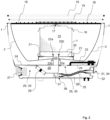
- Fig. 2 shows the grill according to the invention with an inserted charcoal combustion chamber 15.
- the charcoal combustion chamber 15 has a perforated wall and is closed with a lid 16.
- the lid 16 is equipped with a lifting eye 17, which serves to attach to a grill grate 18 from below.
- a double railing 19 is provided for securing the grilled food from the side.
- the charcoal combustion chamber 15 has a perforated bottom 20, wherein the perforation serves to allow outside air to flow into the interior of the charcoal combustion chamber.
- an ignition bowl 21 is provided below the charcoal combustion chamber 15, which can be covered with an ignition paste.
- the charcoal combustion chamber 15 stands with its lower edge in the ignition bowl 21 and is more or less immovable there.
- a passage 22a through which an air inlet pipe 23 extends through the carrier bowl 2 to an intermediate floor 24.
- a passage 22b is also provided in the intermediate floor 24, after which the intermediate floor 24 opens into an air space 25 which is supplied with outside air via a fan 26.
- the ignition bowl 21 and the carrier bowl 2 are placed around the air inlet pipe 23.
- the intermediate floor 24 opens into an air space 25 which is supplied with outside air via a fan 26.
- the fan 26 can be operated from outside the housing 1 via a switch 27.
- Batteries or rechargeable batteries are provided in a battery compartment 28 for power supply.
- Fig. 2 also shows the provision of a slide device 29, over which a slide 30 can be moved.
- the slide 30 In the state shown, the slide 30 is in the position that releases the air flow from the air space 25 to the air inlet pipe 23.
- the external gas connection device 31 is blocked by a blocking element 32, wherein the blocking element 32 can be moved into the blocking position according to Fig. 2
- the rod 33 serves to actuate or move the slide device 29 or the slide 30.
- Fig. 2 gas connection not activated by the slide device 29 shows Fig. 2 the external gas connection device 31 in the state blocked by the blocking element 32, the external gas connection 34, an internal gas connection line 35 and an internal gas connection 36, which, angled or rotated by 90°, has an internal thread 37 for inserting and screwing in a Fig. 2 gas riser pipe (not shown).
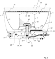
- Fig. 3 shows the grill according to the invention with an inserted gas combustion chamber 38.
- the gas combustion chamber 38 like the charcoal combustion chamber, comprises a perforated housing 1 with a lid 16 attached, the lid 16 being firmly connected to the housing 1.
- the grill grate 18 with the railing 19 is arranged above the lid 16 or above a lifting eye 17, whereby the gas combustion chamber 38 is secured.
- the gas combustion chamber 38 comprises an opening 39 in the lower area through which the gas can be ignited from outside.
- a gas burner 40 is arranged within the gas combustion chamber 38 and is supplied with gas via a gas riser pipe 41.
- the connection between the gas riser pipe 41 and the gas burner 40 is gas-tight.
- the gas combustion chamber 38 stands on the carrier shell 2 and is positioned there by means of a support device 42.
- the support device 42 can be an integral part of the gas combustion chamber 38, in particular of the inwardly offset bottom 43 therein.
- the gas riser pipe 41 extends from the gas burner 40 through the base 43 of the gas combustion chamber 38, through a central passage in the carrier shell 2 and through an intermediate base 24 which encloses or carries the slide device 29.
- the slide device 29 or the slide 30 is in the position used to connect the gas combustion chamber 38, so that the gas riser pipe 41 can be screwed into a connection block 44 of the inner gas connection 36.
- Suitable sealing means 45 can be interposed.
- the gas coming from a gas tank for example a cartridge, a gas cartridge, etc., possibly with the interposition of a regulator, can flow in and reaches the gas burner 40 via the intended flow path.
- a gas tank for example a cartridge, a gas cartridge, etc.
- Fig. 3 also shows that the locking element 32 is in the open position.
- the slide 30 or the locking device 29 is brought into the position suitable for the connection of the gas combustion chamber 38.
- the air inlet pipe 23 serves as a gas riser pipe 41.
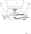
- Fig. 4 shows a further embodiment with an inserted gas burner 40, without the provision of a gas combustion chamber.
- a base 46 is provided around the gas burner 40, which can include individual base elements, for example in the form of fingers.
- the base 46 is used to position a pot 47.
- the gas burner 40 is arranged lower in the middle of the base 46, which in turn is supported by a gas riser pipe 41.
- a special support element 48 is provided, which can be attached directly to the gas riser pipe 41 or to a sleeve 49 surrounding the gas riser pipe 41.
- the Fig. 5 and 6 show in part an external view of the housing 1 with ventilation slots 50.
- the housing 1 is positioned on support studs 51. These can be, at least partially, height-adjustable.
- the Fig. 5 and 6 show from outside the housing 1 the external gas connection 34 with a gas connection socket 52 for locking insertion or screwing in of a conventional gas connection with gas connection line. According to the illustration in Fig. 5 Due to the slide position not shown, the locking element 32 is away from the insertion area. The gas connection socket 52 is thus free and an external gas connection element can be inserted.
- Fig. 6 shows the gas connection socket 52 in the locked state, after which the external gas connection device 31 is closed via the locking element 32.
Landscapes
- Engineering & Computer Science (AREA)
- Food Science & Technology (AREA)
- Baking, Grill, Roasting (AREA)
Priority Applications (2)
| Application Number | Priority Date | Filing Date | Title |
|---|---|---|---|
| SI202230121T SI4199794T1 (sl) | 2021-11-09 | 2022-08-17 | Žar ali kuhalnik |
| HRP20250486TT HRP20250486T1 (hr) | 2021-11-09 | 2022-08-17 | Roštilj ili uređaj za kuhanje |
Applications Claiming Priority (2)
| Application Number | Priority Date | Filing Date | Title |
|---|---|---|---|
| DE102021212606.5A DE102021212606A1 (de) | 2021-11-09 | 2021-11-09 | Grill, Kocher oder dergleichen |
| PCT/DE2022/200187 WO2023083421A1 (de) | 2021-11-09 | 2022-08-17 | Grill oder kocher |
Publications (2)
| Publication Number | Publication Date |
|---|---|
| EP4199794A1 EP4199794A1 (de) | 2023-06-28 |
| EP4199794B1 true EP4199794B1 (de) | 2025-01-29 |
Family
ID=83283481
Family Applications (1)
| Application Number | Title | Priority Date | Filing Date |
|---|---|---|---|
| EP22769081.5A Active EP4199794B1 (de) | 2021-11-09 | 2022-08-17 | Grill oder kocher |
Country Status (13)
| Country | Link |
|---|---|
| US (1) | US20250009179A1 (da) |
| EP (1) | EP4199794B1 (da) |
| CN (1) | CN118338825A (da) |
| DE (1) | DE102021212606A1 (da) |
| DK (1) | DK4199794T3 (da) |
| ES (1) | ES3023848T3 (da) |
| FI (1) | FI4199794T3 (da) |
| HR (1) | HRP20250486T1 (da) |
| LT (1) | LT4199794T (da) |
| PL (1) | PL4199794T3 (da) |
| PT (1) | PT4199794T (da) |
| SI (1) | SI4199794T1 (da) |
| WO (1) | WO2023083421A1 (da) |
Families Citing this family (1)
| Publication number | Priority date | Publication date | Assignee | Title |
|---|---|---|---|---|
| CN121313022A (zh) * | 2024-07-11 | 2026-01-13 | 广东美的厨房电器制造有限公司 | 烤炉 |
Family Cites Families (7)
| Publication number | Priority date | Publication date | Assignee | Title |
|---|---|---|---|---|
| DE202004017817U1 (de) | 2004-11-17 | 2005-02-10 | Wedermann, Andre | Vorrichtung zum schonenden Garen von Gargut |
| SI2785227T1 (sl) | 2012-12-19 | 2016-02-29 | Lotusgrill Gmbh | Žar |
| KR20150000117A (ko) * | 2013-06-24 | 2015-01-02 | 강선구 | 휴대용 가스 겸용 숯불 바베큐 그릴 |
| MX2016002463A (es) | 2013-08-29 | 2016-06-24 | Brand Developers Aust Pty Ltd | Parrilla. |
| DE102015221099A1 (de) | 2015-10-12 | 2017-04-13 | Lotusgrill Gmbh | Vorrichtung zum Kochen und/oder Grillen |
| GR1009151B (el) | 2016-08-09 | 2017-11-03 | Χαραλαμπος Αλεξανδρου Συγγελακης | Πολυψησταρια |
| US20180325314A1 (en) * | 2017-05-09 | 2018-11-15 | Phase 2, Llc | Grills having flavorizing material containers |
-
2021
- 2021-11-09 DE DE102021212606.5A patent/DE102021212606A1/de not_active Ceased
-
2022
- 2022-08-17 CN CN202280078568.8A patent/CN118338825A/zh active Pending
- 2022-08-17 FI FIEP22769081.5T patent/FI4199794T3/fi active
- 2022-08-17 WO PCT/DE2022/200187 patent/WO2023083421A1/de not_active Ceased
- 2022-08-17 PL PL22769081.5T patent/PL4199794T3/pl unknown
- 2022-08-17 PT PT227690815T patent/PT4199794T/pt unknown
- 2022-08-17 SI SI202230121T patent/SI4199794T1/sl unknown
- 2022-08-17 US US18/708,372 patent/US20250009179A1/en active Pending
- 2022-08-17 DK DK22769081.5T patent/DK4199794T3/da active
- 2022-08-17 EP EP22769081.5A patent/EP4199794B1/de active Active
- 2022-08-17 LT LTEPPCT/DE2022/200187T patent/LT4199794T/lt unknown
- 2022-08-17 HR HRP20250486TT patent/HRP20250486T1/hr unknown
- 2022-08-17 ES ES22769081T patent/ES3023848T3/es active Active
Also Published As
| Publication number | Publication date |
|---|---|
| US20250009179A1 (en) | 2025-01-09 |
| SI4199794T1 (sl) | 2025-07-31 |
| DE102021212606A1 (de) | 2023-05-11 |
| ES3023848T3 (en) | 2025-06-03 |
| FI4199794T3 (fi) | 2025-05-05 |
| WO2023083421A1 (de) | 2023-05-19 |
| LT4199794T (lt) | 2025-05-12 |
| CN118338825A (zh) | 2024-07-12 |
| PT4199794T (pt) | 2025-05-02 |
| PL4199794T3 (pl) | 2025-06-02 |
| EP4199794A1 (de) | 2023-06-28 |
| DK4199794T3 (da) | 2025-04-28 |
| HRP20250486T1 (hr) | 2025-06-20 |
Similar Documents
| Publication | Publication Date | Title |
|---|---|---|
| EP3010382B1 (de) | Grill und holzkohlekammer | |
| EP2785227B1 (de) | Grill | |
| DE202019006135U1 (de) | Zusammenlegbare Grillvorrichtung mit gasbetriebener Heizeinrichtung | |
| WO2017220088A1 (de) | Grill, kocher und holzkohlekammer für einen grill, kocher | |
| EP2979594A1 (de) | Tragbarer kocher | |
| EP4199794A1 (de) | Grill oder kocher | |
| DE102015209010A1 (de) | Grill und Holzkohlekammer | |
| EP3682165B1 (de) | Gasbrenner, gasbrenneranordnung und haushaltsgargerät | |
| EP3442384B1 (de) | Leitblech und zugehöriger grill | |
| WO2017220089A1 (de) | Grill und/oder kocher | |
| EP3114974A1 (de) | Garvorrichtung | |
| DE202012100411U1 (de) | Grillgerät | |
| DE202018006715U1 (de) | Zusammenlegbare Grillvorrichtung mit gasbetriebener Heizeinrichtung | |
| AT512013A2 (de) | Brennvorrichtung insbesondere zum Verbrennen von Ethanol | |
| DE102015221099A1 (de) | Vorrichtung zum Kochen und/oder Grillen | |
| DE3302083C2 (de) | Brenneinsatz für ein Kochgerät | |
| CH716203B1 (de) | Grill. | |
| DE202024101194U1 (de) | Zusammenlegbare Gasfeuerstelle | |
| DE202026101394U1 (de) | Zusammenlegbare Grillvorrichtung mit gasbetriebener Heizeinrichtung und verbesserter Flammabdeckung | |
| EP4193894A1 (de) | Outdoor-gasgrill | |
| EP3155938A1 (de) | Vorrichtung zum kochen und/oder grillen | |
| EP4660527A1 (de) | Doppelkammerrohrbrenner zum lösbaren einsetzen in portable gasgrills | |
| DE20317505U1 (de) | Brenner für Bratrost | |
| DE2541766A1 (de) | Geraet zur warmwasserbereitung und -speicherung | |
| WO2022040706A1 (de) | Aufsatzgerät |
Legal Events
| Date | Code | Title | Description |
|---|---|---|---|
| REG | Reference to a national code |
Ref country code: HR Ref legal event code: TUEP Ref document number: P20250486T Country of ref document: HR |
|
| STAA | Information on the status of an ep patent application or granted ep patent |
Free format text: STATUS: UNKNOWN |
|
| STAA | Information on the status of an ep patent application or granted ep patent |
Free format text: STATUS: THE INTERNATIONAL PUBLICATION HAS BEEN MADE |
|
| PUAI | Public reference made under article 153(3) epc to a published international application that has entered the european phase |
Free format text: ORIGINAL CODE: 0009012 |
|
| STAA | Information on the status of an ep patent application or granted ep patent |
Free format text: STATUS: REQUEST FOR EXAMINATION WAS MADE |
|
| 17P | Request for examination filed |
Effective date: 20230214 |
|
| AK | Designated contracting states |
Kind code of ref document: A1 Designated state(s): AL AT BE BG CH CY CZ DE DK EE ES FI FR GB GR HR HU IE IS IT LI LT LU LV MC MK MT NL NO PL PT RO RS SE SI SK SM TR |
|
| GRAP | Despatch of communication of intention to grant a patent |
Free format text: ORIGINAL CODE: EPIDOSNIGR1 |
|
| STAA | Information on the status of an ep patent application or granted ep patent |
Free format text: STATUS: GRANT OF PATENT IS INTENDED |
|
| DAV | Request for validation of the european patent (deleted) | ||
| DAX | Request for extension of the european patent (deleted) | ||
| INTG | Intention to grant announced |
Effective date: 20241011 |
|
| GRAS | Grant fee paid |
Free format text: ORIGINAL CODE: EPIDOSNIGR3 |
|
| P01 | Opt-out of the competence of the unified patent court (upc) registered |
Free format text: CASE NUMBER: APP_60957/2024 Effective date: 20241113 |
|
| GRAA | (expected) grant |
Free format text: ORIGINAL CODE: 0009210 |
|
| STAA | Information on the status of an ep patent application or granted ep patent |
Free format text: STATUS: THE PATENT HAS BEEN GRANTED |
|
| AK | Designated contracting states |
Kind code of ref document: B1 Designated state(s): AL AT BE BG CH CY CZ DE DK EE ES FI FR GB GR HR HU IE IS IT LI LT LU LV MC MK MT NL NO PL PT RO RS SE SI SK SM TR |
|
| REG | Reference to a national code |
Ref country code: GB Ref legal event code: FG4D Free format text: NOT ENGLISH |
|
| REG | Reference to a national code |
Ref country code: CH Ref legal event code: EP |
|
| REG | Reference to a national code |
Ref country code: DE Ref legal event code: R096 Ref document number: 502022002818 Country of ref document: DE |
|
| REG | Reference to a national code |
Ref country code: IE Ref legal event code: FG4D Free format text: LANGUAGE OF EP DOCUMENT: GERMAN |
|
| REG | Reference to a national code |
Ref country code: DK Ref legal event code: T3 Effective date: 20250425 |
|
| REG | Reference to a national code |
Ref country code: PT Ref legal event code: SC4A Ref document number: 4199794 Country of ref document: PT Date of ref document: 20250502 Kind code of ref document: T Free format text: AVAILABILITY OF NATIONAL TRANSLATION Effective date: 20250424 |
|
| REG | Reference to a national code |
Ref country code: FI Ref legal event code: FGE |
|
| REG | Reference to a national code |
Ref country code: NL Ref legal event code: FP |
|
| REG | Reference to a national code |
Ref country code: SE Ref legal event code: TRGR |
|
| REG | Reference to a national code |
Ref country code: ES Ref legal event code: FG2A Ref document number: 3023848 Country of ref document: ES Kind code of ref document: T3 Effective date: 20250603 |
|
| REG | Reference to a national code |
Ref country code: SK Ref legal event code: T3 Ref document number: E 46274 Country of ref document: SK |
|
| REG | Reference to a national code |
Ref country code: HR Ref legal event code: T1PR Ref document number: P20250486 Country of ref document: HR |
|
| PG25 | Lapsed in a contracting state [announced via postgrant information from national office to epo] |
Ref country code: RS Free format text: LAPSE BECAUSE OF FAILURE TO SUBMIT A TRANSLATION OF THE DESCRIPTION OR TO PAY THE FEE WITHIN THE PRESCRIBED TIME-LIMIT Effective date: 20250429 |
|
| PG25 | Lapsed in a contracting state [announced via postgrant information from national office to epo] |
Ref country code: BG Free format text: LAPSE BECAUSE OF FAILURE TO SUBMIT A TRANSLATION OF THE DESCRIPTION OR TO PAY THE FEE WITHIN THE PRESCRIBED TIME-LIMIT Effective date: 20250129 |
|
| REG | Reference to a national code |
Ref country code: EE Ref legal event code: FG4A Ref document number: E025074 Country of ref document: EE Effective date: 20250428 |
|
| REG | Reference to a national code |
Ref country code: GR Ref legal event code: EP Ref document number: 20250400836 Country of ref document: GR Effective date: 20250613 |
|
| REG | Reference to a national code |
Ref country code: HR Ref legal event code: ODRP Ref document number: P20250486 Country of ref document: HR Payment date: 20250808 Year of fee payment: 4 |
|
| PGFP | Annual fee paid to national office [announced via postgrant information from national office to epo] |
Ref country code: NL Payment date: 20250821 Year of fee payment: 4 Ref country code: LU Payment date: 20250820 Year of fee payment: 4 |
|
| PG25 | Lapsed in a contracting state [announced via postgrant information from national office to epo] |
Ref country code: SM Free format text: LAPSE BECAUSE OF FAILURE TO SUBMIT A TRANSLATION OF THE DESCRIPTION OR TO PAY THE FEE WITHIN THE PRESCRIBED TIME-LIMIT Effective date: 20250129 |
|
| PGFP | Annual fee paid to national office [announced via postgrant information from national office to epo] |
Ref country code: FI Payment date: 20250820 Year of fee payment: 4 Ref country code: ES Payment date: 20250917 Year of fee payment: 4 Ref country code: PT Payment date: 20250801 Year of fee payment: 4 |
|
| PGFP | Annual fee paid to national office [announced via postgrant information from national office to epo] |
Ref country code: LT Payment date: 20250731 Year of fee payment: 4 Ref country code: DK Payment date: 20250821 Year of fee payment: 4 |
|
| PGFP | Annual fee paid to national office [announced via postgrant information from national office to epo] |
Ref country code: NO Payment date: 20250820 Year of fee payment: 4 Ref country code: GR Payment date: 20250819 Year of fee payment: 4 |
|
| PGFP | Annual fee paid to national office [announced via postgrant information from national office to epo] |
Ref country code: TR Payment date: 20250808 Year of fee payment: 4 Ref country code: PL Payment date: 20250813 Year of fee payment: 4 Ref country code: IT Payment date: 20250901 Year of fee payment: 4 |
|
| PGFP | Annual fee paid to national office [announced via postgrant information from national office to epo] |
Ref country code: BE Payment date: 20250820 Year of fee payment: 4 |
|
| PGFP | Annual fee paid to national office [announced via postgrant information from national office to epo] |
Ref country code: HR Payment date: 20250808 Year of fee payment: 4 |
|
| PGFP | Annual fee paid to national office [announced via postgrant information from national office to epo] |
Ref country code: AT Payment date: 20251020 Year of fee payment: 4 Ref country code: FR Payment date: 20250821 Year of fee payment: 4 |
|
| PGFP | Annual fee paid to national office [announced via postgrant information from national office to epo] |
Ref country code: MT Payment date: 20250820 Year of fee payment: 4 Ref country code: CH Payment date: 20250901 Year of fee payment: 4 Ref country code: SE Payment date: 20250821 Year of fee payment: 4 |
|
| PGFP | Annual fee paid to national office [announced via postgrant information from national office to epo] |
Ref country code: EE Payment date: 20250901 Year of fee payment: 4 Ref country code: IE Payment date: 20250821 Year of fee payment: 4 Ref country code: CZ Payment date: 20250801 Year of fee payment: 4 |
|
| PGFP | Annual fee paid to national office [announced via postgrant information from national office to epo] |
Ref country code: RO Payment date: 20250811 Year of fee payment: 4 |
|
| PGFP | Annual fee paid to national office [announced via postgrant information from national office to epo] |
Ref country code: SK Payment date: 20250808 Year of fee payment: 4 |
|
| PGFP | Annual fee paid to national office [announced via postgrant information from national office to epo] |
Ref country code: IS Payment date: 20250815 Year of fee payment: 4 |
|
| PGFP | Annual fee paid to national office [announced via postgrant information from national office to epo] |
Ref country code: LV Payment date: 20250821 Year of fee payment: 4 |
|
| REG | Reference to a national code |
Ref country code: DE Ref legal event code: R097 Ref document number: 502022002818 Country of ref document: DE |
|
| PGFP | Annual fee paid to national office [announced via postgrant information from national office to epo] |
Ref country code: SI Payment date: 20250801 Year of fee payment: 4 |
|
| PLBE | No opposition filed within time limit |
Free format text: ORIGINAL CODE: 0009261 |
|
| STAA | Information on the status of an ep patent application or granted ep patent |
Free format text: STATUS: NO OPPOSITION FILED WITHIN TIME LIMIT |
|
| 26N | No opposition filed |
Effective date: 20251030 |
|
| PGFP | Annual fee paid to national office [announced via postgrant information from national office to epo] |
Ref country code: DE Payment date: 20251030 Year of fee payment: 4 |
|
| PGFP | Annual fee paid to national office [announced via postgrant information from national office to epo] |
Ref country code: CY Payment date: 20250804 Year of fee payment: 4 |
|
| PG25 | Lapsed in a contracting state [announced via postgrant information from national office to epo] |
Ref country code: MC Free format text: LAPSE BECAUSE OF FAILURE TO SUBMIT A TRANSLATION OF THE DESCRIPTION OR TO PAY THE FEE WITHIN THE PRESCRIBED TIME-LIMIT Effective date: 20250129 |