EP4199806B1 - Erkennung der magnetfeldrichtung - Google Patents
Erkennung der magnetfeldrichtung Download PDFInfo
- Publication number
- EP4199806B1 EP4199806B1 EP21777909.9A EP21777909A EP4199806B1 EP 4199806 B1 EP4199806 B1 EP 4199806B1 EP 21777909 A EP21777909 A EP 21777909A EP 4199806 B1 EP4199806 B1 EP 4199806B1
- Authority
- EP
- European Patent Office
- Prior art keywords
- magnetic field
- sensor
- magnetometers
- magnetometer
- field source
- Prior art date
- Legal status (The legal status is an assumption and is not a legal conclusion. Google has not performed a legal analysis and makes no representation as to the accuracy of the status listed.)
- Active
Links
Images


Classifications
-
- A—HUMAN NECESSITIES
- A61—MEDICAL OR VETERINARY SCIENCE; HYGIENE
- A61M—DEVICES FOR INTRODUCING MEDIA INTO, OR ONTO, THE BODY; DEVICES FOR TRANSDUCING BODY MEDIA OR FOR TAKING MEDIA FROM THE BODY; DEVICES FOR PRODUCING OR ENDING SLEEP OR STUPOR
- A61M25/00—Catheters; Hollow probes
- A61M25/01—Introducing, guiding, advancing, emplacing or holding catheters
- A61M25/0105—Steering means as part of the catheter or advancing means; Markers for positioning
- A61M25/0127—Magnetic means; Magnetic markers
-
- A—HUMAN NECESSITIES
- A61—MEDICAL OR VETERINARY SCIENCE; HYGIENE
- A61B—DIAGNOSIS; SURGERY; IDENTIFICATION
- A61B5/00—Measuring for diagnostic purposes; Identification of persons
- A61B5/06—Devices, other than using radiation, for detecting or locating foreign bodies ; Determining position of diagnostic devices within or on the body of the patient
- A61B5/061—Determining position of a probe within the body employing means separate from the probe, e.g. sensing internal probe position employing impedance electrodes on the surface of the body
- A61B5/062—Determining position of a probe within the body employing means separate from the probe, e.g. sensing internal probe position employing impedance electrodes on the surface of the body using magnetic field
-
- G—PHYSICS
- G01—MEASURING; TESTING
- G01R—MEASURING ELECTRIC VARIABLES; MEASURING MAGNETIC VARIABLES
- G01R33/00—Arrangements or instruments for measuring magnetic variables
- G01R33/02—Measuring direction or magnitude of magnetic fields or magnetic flux
-
- A—HUMAN NECESSITIES
- A61—MEDICAL OR VETERINARY SCIENCE; HYGIENE
- A61B—DIAGNOSIS; SURGERY; IDENTIFICATION
- A61B5/00—Measuring for diagnostic purposes; Identification of persons
- A61B5/72—Signal processing specially adapted for physiological signals or for diagnostic purposes
- A61B5/7203—Signal processing specially adapted for physiological signals or for diagnostic purposes for noise prevention, reduction or removal
-
- A—HUMAN NECESSITIES
- A61—MEDICAL OR VETERINARY SCIENCE; HYGIENE
- A61B—DIAGNOSIS; SURGERY; IDENTIFICATION
- A61B5/00—Measuring for diagnostic purposes; Identification of persons
- A61B5/74—Details of notification to user or communication with user or patient; User input means
- A61B5/742—Details of notification to user or communication with user or patient; User input means using visual displays
- A61B5/743—Displaying an image simultaneously with additional graphical information, e.g. symbols, charts, function plots
-
- A—HUMAN NECESSITIES
- A61—MEDICAL OR VETERINARY SCIENCE; HYGIENE
- A61B—DIAGNOSIS; SURGERY; IDENTIFICATION
- A61B5/00—Measuring for diagnostic purposes; Identification of persons
- A61B5/74—Details of notification to user or communication with user or patient; User input means
- A61B5/742—Details of notification to user or communication with user or patient; User input means using visual displays
- A61B5/7435—Displaying user selection data, e.g. icons in a graphical user interface
-
- A—HUMAN NECESSITIES
- A61—MEDICAL OR VETERINARY SCIENCE; HYGIENE
- A61B—DIAGNOSIS; SURGERY; IDENTIFICATION
- A61B5/00—Measuring for diagnostic purposes; Identification of persons
- A61B5/74—Details of notification to user or communication with user or patient; User input means
- A61B5/7475—User input or interface means, e.g. keyboard, pointing device, joystick
-
- A—HUMAN NECESSITIES
- A61—MEDICAL OR VETERINARY SCIENCE; HYGIENE
- A61B—DIAGNOSIS; SURGERY; IDENTIFICATION
- A61B2562/00—Details of sensors; Constructional details of sensor housings or probes; Accessories for sensors
- A61B2562/04—Arrangements of multiple sensors of the same type
- A61B2562/046—Arrangements of multiple sensors of the same type in a matrix array
-
- A—HUMAN NECESSITIES
- A61—MEDICAL OR VETERINARY SCIENCE; HYGIENE
- A61M—DEVICES FOR INTRODUCING MEDIA INTO, OR ONTO, THE BODY; DEVICES FOR TRANSDUCING BODY MEDIA OR FOR TAKING MEDIA FROM THE BODY; DEVICES FOR PRODUCING OR ENDING SLEEP OR STUPOR
- A61M25/00—Catheters; Hollow probes
- A61M25/01—Introducing, guiding, advancing, emplacing or holding catheters
- A61M25/0105—Steering means as part of the catheter or advancing means; Markers for positioning
- A61M2025/0166—Sensors, electrodes or the like for guiding the catheter to a target zone, e.g. image guided or magnetically guided
-
- A—HUMAN NECESSITIES
- A61—MEDICAL OR VETERINARY SCIENCE; HYGIENE
- A61M—DEVICES FOR INTRODUCING MEDIA INTO, OR ONTO, THE BODY; DEVICES FOR TRANSDUCING BODY MEDIA OR FOR TAKING MEDIA FROM THE BODY; DEVICES FOR PRODUCING OR ENDING SLEEP OR STUPOR
- A61M2205/00—General characteristics of the apparatus
- A61M2205/33—Controlling, regulating or measuring
- A61M2205/3317—Electromagnetic, inductive or dielectric measuring means
-
- A—HUMAN NECESSITIES
- A61—MEDICAL OR VETERINARY SCIENCE; HYGIENE
- A61M—DEVICES FOR INTRODUCING MEDIA INTO, OR ONTO, THE BODY; DEVICES FOR TRANSDUCING BODY MEDIA OR FOR TAKING MEDIA FROM THE BODY; DEVICES FOR PRODUCING OR ENDING SLEEP OR STUPOR
- A61M2205/00—General characteristics of the apparatus
- A61M2205/35—Communication
- A61M2205/3546—Range
- A61M2205/3561—Range local, e.g. within room or hospital
-
- A—HUMAN NECESSITIES
- A61—MEDICAL OR VETERINARY SCIENCE; HYGIENE
- A61M—DEVICES FOR INTRODUCING MEDIA INTO, OR ONTO, THE BODY; DEVICES FOR TRANSDUCING BODY MEDIA OR FOR TAKING MEDIA FROM THE BODY; DEVICES FOR PRODUCING OR ENDING SLEEP OR STUPOR
- A61M2205/00—General characteristics of the apparatus
- A61M2205/58—Means for facilitating use, e.g. by people with impaired vision
- A61M2205/583—Means for facilitating use, e.g. by people with impaired vision by visual feedback
-
- A—HUMAN NECESSITIES
- A61—MEDICAL OR VETERINARY SCIENCE; HYGIENE
- A61M—DEVICES FOR INTRODUCING MEDIA INTO, OR ONTO, THE BODY; DEVICES FOR TRANSDUCING BODY MEDIA OR FOR TAKING MEDIA FROM THE BODY; DEVICES FOR PRODUCING OR ENDING SLEEP OR STUPOR
- A61M2205/00—General characteristics of the apparatus
- A61M2205/60—General characteristics of the apparatus with identification means
- A61M2205/6054—Magnetic identification systems
Definitions
- US 2018/221610 A1 discloses a system for facilitating endotracheal intubation that includes one or more magnetometers arranged relative to a video laryngoscope body and configured to generate magnetometer signals based on an interaction with one or more magnetic elements associated with an intubation device.
- US 2019/239976 A1 discloses tissue expander containing a magnet and a device for detecting the magnet.
- Disclosed herein is a system for magnetic field direction detection when placing a catheter according to claim 1.
- the system includes a console wired to the sensor.
- the system includes a console wirelessly coupled to the sensor.
- the system includes a console in communication with the display.
- the system includes a console including one or more thresholds corresponding to a measured strength of the magnetic field source at a known distance from the sensor.
- the senor is configured to be placed on a body of a patient and perform a medical device tip location tracking process.
- an apparatus for magnetic field direction detection when placing a catheter including a sensor housing, a magnetic sensor printed circuit board (PCB), coupled to the sensor housing, having a plurality of magnetometers arranged in a magnetometer array, where the magnetic sensor PCB provides, to a console device, a magnetic field strength value detected by each magnetometer and a magnetometer ID of a corresponding magnetometer where the magnetic field strength values and corresponding magnetometer IDs indicate a direction of the magnetic field source relative to the apparatus based on a positioning of each magnetometer and the magnetic field strength value detected by each magnetometer.
- PCB magnetic sensor printed circuit board
- the apparatus includes a PCB including a rectangular arranged magnetometer array.
- the apparatus includes a PCB including an elliptical arranged magnetometer array.
- the method includes detecting a magnetic field by a sensor includes recording an identifier of each magnetometer in the plurality of magnetometers and detected magnetic field strength value at each magnetometer in the plurality of magnetometers.
- the method includes generating a graphic includes generating one or more of a reference icon, a magnetic field source icon or a magnetic field source direction icon.
- generating a graphic includes generating a graphic that illustrates the magnetic field source is no longer detected by the sensor.
- generating a graphic includes generating a graphic that receives user input confirming the magnetic field source has been removed.
- logic is representative of hardware, firmware or software that is configured to perform one or more functions.
- logic may include circuitry having data processing or storage functionality. Examples of such circuitry may include, but are not limited or restricted to a hardware processor (e.g., microprocessor with one or more processor cores, a digital signal processor, a programmable gate array, a microcontroller, an application specific integrated circuit "ASIC,” etc.), a semiconductor memory, or combinatorial elements.
- a hardware processor e.g., microprocessor with one or more processor cores, a digital signal processor, a programmable gate array, a microcontroller, an application specific integrated circuit "ASIC,” etc.
- ASIC application specific integrated circuit
- logic may be software, such as executable code in the form of an executable application, an Application Programming Interface (API), a subroutine, a function, a procedure, an applet, a servlet, a routine, source code, object code, a shared library/dynamic load library, or one or more instructions.
- the software may be stored in any type of a suitable non-transitory storage medium, or transitory storage medium (e.g., electrical, optical, acoustical or other form of propagated signals such as carrier waves, infrared signals, or digital signals).
- non-transitory storage medium may include, but are not limited or restricted to a programmable circuit; semiconductor memory; non-persistent storage such as volatile memory (e.g., any type of random access memory "RAM”); or persistent storage such as non-volatile memory (e.g., read-only memory "ROM,” power-backed RAM, flash memory, phase-change memory, etc.), a solid-state drive, hard disk drive, an optical disc drive, or a portable memory device.
- volatile memory e.g., any type of random access memory "RAM”
- persistent storage such as non-volatile memory (e.g., read-only memory "ROM,” power-backed RAM, flash memory, phase-change memory, etc.), a solid-state drive, hard disk drive, an optical disc drive, or a portable memory device.
- the executable code may be stored in persistent storage.
- FIG. 1 illustrates a plan view of a system 100 for magnetic field direction detection when placing a catheter including a console 110 coupled to a sensor 130 including a magnetic sensor printed circuit board (“PCB”) 140 with a plurality of magnetometers 142 in a magnetometer array 144, in accordance with some embodiments.
- the system 100 includes the console 110 having a processor 150 and non-transitory computer readable medium (“memory”) 160 having a plurality of logic modules that are configured to perform operations that will be described in more detail.
- memory non-transitory computer readable medium
- the console 110 can be coupled to a display 120 on which graphics can be generated to illustrate the direction of a magnetic field source 200 including one or more of a sensor icon 122, a magnetic field source icon 124, or a magnetic field source direction icon 126.
- the sensor 130 may be configured to be placed on a body of a patient and perform a medical device tip location tracking process.
- the sensor 130 includes a sensor housing 148 coupled to the magnetic sensor PCB 140 having a plurality of magnetometers 142 arranged in a magnetometer array 144 configured to detect the presence of a magnetic field source 200 through detection of a magnetic field generated thereby.
- the magnetic sensor PCB 140 may be configured such that each of the plurality of magnetometers 142 in a magnetometer array 144 measures a magnetic field strength, where each measurement is communicated to the console 110.
- the magnetic sensor PCB 140 communicates a series of magnetic field strength measurements (e.g., values) with a magnetometer ID of the corresponding magnetometer 142 in the magnetometer array 144 to the console 110.
- the console 110 may be configured to receive the magnetic field strength measurements from the plurality of magnetometers 142 and to determine the direction of the magnetic field source 200 based on the received magnetic field strength measurements.
- the console 110 may be configured to indicate the direction of the magnetic field source 200 on the display 120 through generating a graphic that may include one or more of the reference icon 122, the magnetic field source icon 124 or the direction icon 126.
- the reference icon 122 can include an icon of a sensor, a rectangle, an X, a circle, or the like.
- the magnetic field source icon 124 can include an icon of a bar magnet, an icon of a horseshoe magnet, an icon of a cylindrical magnet or the like.
- the direction icon 126 can include an arrow, a line, a finger or the like.
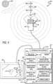
- the reference icon 122 may be configured to be centered on the display 120 with the magnetic field source icon 124 and the direction icon 126 being located 360° around the reference icon 122, with the direction icon 126 being displayed in the direction the console 110 has determined for the magnetic field source 200 (see FIG. 4 ).
- FIG 2 illustrates a block diagram depicting various elements of the system for magnetic field direction detection when placing a catheter including the console 110 and the sensor 130 including the magnetic sensor PCB 140 coupled to the sensor housing 148, having a plurality of magnetometers 142 arranged in a magnetometer array 144.
- the console 110 is shown to include one or more processors 150, a communication interface 152, the display 120 and the memory" 160, having a plurality of logic modules including a magnetometer acquisition logic 162, a magnetic field source determination logic 164 and a display logic 166.
- the console 110 includes the memory 160, which when executed by the processor 150 can be configured to perform operations including receiving magnetic field strength values detected by the plurality of magnetometers 142, determining a position on the sensor of each of the plurality of magnetometers 142, determining a direction of a magnetic field source 200 relative to the sensor 130 based on the detected magnetic field strength values and the position on the sensor 130 of each of the plurality of magnetometers 142, and generating a graphic configured to illustrate the direction of the magnetic field source200 on the display 200.
- the memory 160 may optionally include data stores such as magnetic field source direction data 168, magnetometer measurement data 170 and the relation data 172.
- the magnetometer acquisition logic 162 receives communications from the sensor 130 including the magnetic sensor PCB 140, wherein the communications may be a series of magnetic field strength measurement values paired with a magnetometer ID of the corresponding magnetometer 142 in the magnetometer array 144.
- the communication may also include a location within the magnetometer array 144 along with the magnetic field strength measurement value and the magnetometer ID (i.e. a tuple).
- the magnetometer acquisition logic 162 performs a lookup for the location of a magnetometer 142 in the magnetometer array 144 based on the magnetometer ID in order to complete the ⁇ magnetic field strength, magnetometer ID, magnetometer location ⁇ tuple.
- the magnetometer ID corresponds to the physical location of each of the plurality of magnetometers 142 in the magnetometer array 144.
- the magnetometer acquisition logic 162 is configured to determine the position on the sensor 130 of each of the plurality of magnetometers 142 based on the magnetometer ID of each of the plurality of magnetometers 142 arranged in the magnetometer array 144.
- the magnetic field source determination logic 166 determines the magnetic field source direction, relative to the sensor 130, using the magnetometer ID from each of the plurality of magnetometers 142 and the measured magnetic field strength values by each magnetometer 142. For instance, in some embodiments, the magnetic field source determination logic 166 determines a direction of the magnetic field source 200 relative to the sensor 130, using at least one threshold that will be described in more detail herein. The magnetic field source determination logic 166 correlates each magnetometer ID with the magnetic field strength value measured at each of the plurality of magnetometers 142 within the magnetometer array 144.
- the display logic 168 is configured to generate a graphic configured to illustrate the direction of the magnetic field source direction on the display 120 using one of a plurality of icons including the reference icon 122, the magnetic field source icon 124 or a magnetic field source direction icon 126.
- the processor 150 includes non-volatile memory such as EEPROM for instance, thus acting as a control processor.
- the display 120 in the present embodiment may be integrated into the console 110 and is used to display information about a magnetic field source 200 to the clinician while using the system 100.
- the display 120 may be separate from the console 110 and may be communicatively coupled by way of a wired communication or a wireless communication including WiFi, Bluetooth, Near Field Communications (NFC), electromagnetic (EM), radio frequency (RF), combinations thereof, or the like.
- the senor 130 including the magnetic sensor PCB 140 is coupled to the console 110. In some embodiments, the sensor 130 including the magnetic sensor PCB 140 can be in wired communication with the console 110. In some embodiments, the console 110 including the magnetic sensor PCB 140 can be communicatively coupled by way of wireless communication. Exemplary wireless communication modalities can include WiFi, Bluetooth, Near Field Communications (NFC), electromagnetic (EM), radio frequency (RF), combinations thereof, or the like.
- the magnetic sensor PCB 140 coupled to the sensor housing 148, can include a plurality of magnetometers 142 arranged in various configurations in a magnetometer array 144. As illustrated in FIG. 3A , the plurality of magnetometers 142 can be arranged in a rectangular configuration on the magnetic sensor PCB 140, coupled to the sensor housing 148. If a magnetic field source 200 is present, the plurality of magnetometers 142 in the magnetometer array 144 are each configured to measure the magnetic field source strength. If a magnetic field source 200 is located on the proximal side of the magnetic sensor PCB 140, as illustrated in FIG.
- the plurality of magnetometers 142 located proximal the magnetic field source 200 will detect higher magnetic field strength values as compared to the plurality of magnetometers 142 located distal the magnetic field source 200, which will detect lower magnetic field strength values.
- the plurality of magnetometers 142 can be arranged in an elliptical configuration magnetometer array 146 on the magnetic sensor PCB 140 coupled to the sensor housing 148, as illustrated in FIG. 3B .
- a system 400 for magnetic field direction detection when placing a catheter can detect the direction of the magnetic field source 200 and distance of the magnetic field source 200.
- FIG. 4 illustrates a block diagram depicting various elements of the system 400 for magnetic field direction detection when placing a catheter including one or more distance thresholds correlating to the measured strength of the magnetic field source at different distances in relation to the sensor 130, in accordance with some embodiments.
- the system 400 includes the console 110 including the processor 150 and memory 460 having stored thereon a plurality of logic modules that, when executed by the processor 150 are configured to perform operation including receiving magnetic field strength values detected by the plurality of magnetometers 142, determining the position on the sensor 130 including the magnetic sensor PCB 140 coupled to the sensor housing 148, of each of the plurality of magnetometers 142, determining the direction of a magnetic field source 200 relative to the sensor 130 based on the detected magnetic field strength values and the position on the sensor 130 of each of the plurality of magnetometers 142, determining a distance, relative to the sensor 130, based on one or more thresholds, and generating the graphic configured to illustrate the direction of the magnetic field source 200 on a display 120.
- the console 110 is shown to include the one or more processors 150, the communication interface 152, the display 120 and the non-transitory, computer-readable medium (“memory") 460.
- the memory 460 is configured to store logic modules including the magnetometer acquisition logic 162, the magnetic field source determination logic 166, a magnetic field threshold distance logic 468, and a display logic 470. Further, the memory 460 may optionally include data stores such as the magnetic field source direction data 170, a magnetic field source distance data 472, the magnetometer measurement data 172 and the relation data 174.
- the magnetometer acquisition logic 162 and the magnetic field source determination logic 166 function as described above.
- the magnetic field threshold distance logic 468 compares a magnetic field reading from the plurality of magnetometers 142 in the magnetometer array 144 to one or more established thresholds corresponding to one or more established distances of a magnetic field source 200 from the sensor 130 including the magnetic sensor PCB 140 as described above.
- the magnetic field threshold distance logic 468 compares magnetic field reading values to a first established threshold corresponding to a magnetic field strength within a first distance 480 ("d 1 ") away from the sensor 130 including the magnetic sensor PCB 140, to a second established threshold corresponding to the magnetic field strength within a second distance 482 ("d 2 ") away from the sensor 130 including the magnetic sensor PCB 140, to a third established threshold corresponding to the magnetic field strength within a third distance 484 ("d 3 ") away from the sensor 130 including the magnetic sensor PCB 140, and a fourth established threshold corresponding to the magnetic field strength within a fourth distance 486 (“d 4 ”) away from the sensor 130 including the magnetic sensor PCB 140.
- the display logic 470 is configured to generate a graphic configured to illustrate the direction of the magnetic field source direction and the distance of the magnetic field source using a plurality of icons including the reference icon 122, the magnetic field source icon 124, the magnetic field source direction icon 126, and a magnetic field source distance icon 428 on the display 120. Further, the magnetic field source direction icon 126 may indicate the distance from the sensor 130 including the magnetic sensor PCB 140 to the detected magnetic field source 200.
- the magnetic field source direction icon 126 includes the magnetic field source distance icon 428 being the text "121.92cm (4ft)."
- the indication of the distance may refer to an approximate distance between the sensor 130 and the detected magnetic field source 200, while in other embodiments, the indication of the distance may utilize one or more thresholds (e.g., 121.92-182.88cm (4-6ft)." where such an indication corresponds to a particular distance threshold).
- the system 100 may be configured to detect the direction of a local magnetic field that may interfere with magnetic tracking devices such as devices and systems for navigation and position a central venous catheter within a patient which can be found, for example, in U.S. Patent No. 8,388,541 ; U.S. Patent No. 8,781,555 ; U.S. Patent No. 8,849,382 ; U.S. Patent No. 9,521,961 ; U.S. Patent No. 9,526,440 ; U.S. Patent No. 9,549,685 ; U.S. Patent No. 9,636,031 ; U.S. Patent No. 9,649,048 ; U.S. Patent No. 9,681,823 ; U.S. Patent No. 9,999,371 ; U.S. Patent No. 10,105,121 ; U.S. Patent No. 10,165,962 ; U.S. Patent No. 10,238,418 ; and U.S. Patent No. 10,602,958 .
- the system 100 may include a console 110 having logic coupled to memory 160, a display 120, and a sensor 130 including a magnetic sensor PCB 140 having a plurality magnetometers 142 arranged in a magnetometer array 144 configured to track the tip of a medical device for proper placement including in some embodiments, a stylet, a wire, or a catheter.
- the sensor 130 may be configured to track the tip of the medical device by measuring a local electromagnetic field.
- a hospital bed can include a remote control (e.g., a magnetic field source 200) or other electronic devices (e.g. cell phones, tables), which can interfere with the sensor 130 configured to track the tip of the medical device by producing a magnetic field and potentially leading to improper placement of the medical device.
- the magnetic sensor PCB 140 including the plurality of magnetometers 142 arranged in the magnetometer array 144 can be configured to measure the magnetic field strength at each of the plurality of magnetometers 142 and can be communicated to the console 110.
- the console 110 can be configured to receive the magnetic field strength measurement values from the plurality of magnetometers 142 and determine, using the logic coupled to memory as described above, to determine the direction of the magnetic field source 200 (e.g., the hospital bed remote control) based upon the magnetic field strength measurement values.
- the console 110 may then alert the user by indicating the direction of the magnetic field source 200 (e.g., the hospital bed remote control) as it relates to the sensor 130 on the display 120 by the use of one or more of the reference icon 122, the magnetic field source icon 124 or the magnetic field source direction icon 126.
- the magnetic field source 200 e.g., the hospital bed remote control
- FIG. 5 illustrates an exemplary method 500 of detecting a magnetic field before placing a catheter, in accordance with some embodiments.
- the method 500 includes detecting a magnetic field by a sensor 130 configured to be placed on a body of a patient and perform a medical device tip location tracking process, the sensor 130 including a magnetic sensor PCB 140 printed circuit board (PCB) including a plurality of magnetometers 142 arranged in a magnetometer array 144 (block 502).
- the detecting a magnetic field by a sensor 130 includes an optional step of recording an identifier of each magnetometer in the plurality of magnetometers 142 and detected magnetic field strength value at each magnetometer in the plurality of magnetometers 142 (block 503).
- the magnetometer array 144 may be arranged in a rectangular shape, an elliptical shape or the like.
- the method 500 further includes correlating the detected magnetic field strength values with a position on the sensor 130, of each of the plurality of magnetometers 142 as arranged in magnetometer array 144 (block 504).
- the correlating includes a console 110 or the sensor 130 including the magnetic sensor PCB 140 having the plurality of magnetometers 142 arranged in a magnetometer array 144 providing a magnetometer ID that corresponds each of the plurality of magnetometers 142 in the magnetometer array 144.
- the console 110 correlates the magnetometer ID with the magnetic field strength values measured at the one or more magnetometers 142 in the magnetometer array 144.
- the method 500 further includes determining a direction of the magnetic field source 200 relative to the sensor 130, wherein the determining is based on the correlating of the detected magnetic field strength values at each of the plurality of magnetometers 142 and the position on the sensor 130 of each of the plurality of magnetometers 142 (block 506).
- the method 500 further includes generating a graphic configured to illustrate the direction of the magnetic field source 200 on a display 120 (block 508).
- the generating a graphic includes generating one or more of a reference icon 122, a magnetic field source icon 124 or a magnetic field source direction icon 126.
- generating a graphic includes generating a graphic that the magnetic field source 200 is no longer detected by the sensor.
- the generating a graphic includes generating a graphic that illustrates the magnetic field source 200 is no longer detected by the sensor 130 including the magnetic sensor PCB 140.
- the generating a graphic includes generating a graphic that receives user input confirming the magnetic field source200 has been removed.
- the generating a graphic includes generating one or more of the reference icon 122, the magnetic field source icon 124, a magnetic field source distance icon 428 or the magnetic field source direction icon 126.
- the optional step of detecting a second magnetic field can occur only after generating a graphic configured to illustrate the direction of the magnetic field source 200 on the display 200 (block 508).
Landscapes
- Health & Medical Sciences (AREA)
- Life Sciences & Earth Sciences (AREA)
- Engineering & Computer Science (AREA)
- Physics & Mathematics (AREA)
- Veterinary Medicine (AREA)
- Biophysics (AREA)
- Public Health (AREA)
- General Health & Medical Sciences (AREA)
- Animal Behavior & Ethology (AREA)
- Heart & Thoracic Surgery (AREA)
- Biomedical Technology (AREA)
- Surgery (AREA)
- Pathology (AREA)
- Medical Informatics (AREA)
- Molecular Biology (AREA)
- Signal Processing (AREA)
- Human Computer Interaction (AREA)
- Anesthesiology (AREA)
- Pulmonology (AREA)
- Hematology (AREA)
- Physiology (AREA)
- Computer Vision & Pattern Recognition (AREA)
- Artificial Intelligence (AREA)
- Condensed Matter Physics & Semiconductors (AREA)
- Psychiatry (AREA)
- General Physics & Mathematics (AREA)
- Nuclear Medicine, Radiotherapy & Molecular Imaging (AREA)
- Radiology & Medical Imaging (AREA)
- Media Introduction/Drainage Providing Device (AREA)
- Measurement And Recording Of Electrical Phenomena And Electrical Characteristics Of The Living Body (AREA)
Claims (12)
- System zur Erkennung der Magnetfeldrichtung beim Platzieren eines Katheters, umfassend:einen Sensor, der konfiguriert ist, um eine medizinische Vorrichtung zu verfolgen, wobei der Sensor eine Magnetsensorleiterplatte, PCB (Printed Circuit Board) (140), einschließt, einschließlich einer Vielzahl von Magnetometern (142), die in einer Magnetometeranordnung (144) angeordnet sind; undeine mit dem Sensor (130) gekoppelten Konsole (110), wobei die Konsole einen Prozessor und ein nichtflüchtiges computerlesbares Medium einschließt, auf dem eine Vielzahl von Logikmodulen gespeichert ist, die, wenn sie vom Prozessor ausgeführt werden, konfiguriert sind, um Operationen auszuführen, einschließend:Empfangen von Magnetfeldstärkewerten, die von der Vielzahl von Magnetometern (142) erfasst werden;Bestimmen einer Position jedes der mehreren Magnetometer (142) auf dem Sensor basierend auf einer Magnetometer-ID jedes der mehreren Magnetometer, die in der Magnetometeranordnung (144) angeordnet sind;Bestimmen einer Richtung einer Magnetfeldquelle relativ zu dem Sensor (130) auf der Grundlage der erfassten Magnetfeldstärkewerte und der Position jedes der mehreren Magnetometer (142) auf dem Sensor;Erzeugen einer Grafik, die konfiguriert ist, um die Richtung der Magnetfeldquelle auf einem Display (120) darzustellen; undKorrelieren jeder Magnetometer-ID mit dem Magnetfeldstärkewert, der an jedem der mehreren Magnetometer (142) innerhalb der Magnetometeranordnung (144) gemessen wird.
- System nach Anspruch 1, wobei die Magnetfeldsensor-PCB (140) der Konsole eine Magnetometer-ID bereitstellt, die jedem der mehreren Magnetometer (142) entspricht, die in der Magnetometeranordnung (144) angeordnet sind.
- System nach einem der Ansprüche 1-2, wobei die Konsole (110) mit dem Sensor (130) verkabelt ist.
- System nach einem der Ansprüche 1-2, wobei die Konsole (110) drahtlos mit dem Sensor (130) gekoppelt ist.
- System nach einem der Ansprüche 1-4, wobei die Konsole (110) mit dem Display (120) in Verbindung steht.
- System nach einem der Ansprüche 1-5, wobei die Konsole (110) einen oder mehrere Schwellwerte einschließt, die einer gemessenen Stärke der Magnetfeldquelle in einem bekannten Abstand vom Sensor entsprechen.
- System nach einem der Ansprüche 1-6, wobei der Sensor konfiguriert ist, um auf dem Körper eines Patienten platziert zu werden.
- Verfahren zum Erfassen eines Magnetfeldes vor dem Einführen eines Katheters, umfassend:Erfassen eines Magnetfelds durch einen Sensor (130), der konfiguriert ist, um eine medizinische Vorrichtung zu verfolgen, der Sensor (130) einschließend eine Magnetsensorleiterplatte, PCB (Printed Circuit Board) (140), einschließlich einer Vielzahl von Magnetometern (142), die in einer Magnetometeranordnung (144) angeordnet sind;Bestimmen einer Position jedes der mehreren Magnetometer (142) auf dem Sensor basierend auf einer Magnetometer-ID jedes der mehreren Magnetometer, die in der Magnetometeranordnung (144) angeordnet sind;Bestimmen einer Richtung der Magnetfeldquelle relativ zum Sensor (130), wobei das Bestimmen auf der Korrelation der erfassten Magnetfeldstärkewerte und der Position jedes der mehreren Magnetometer (142) auf dem Sensor (130) basiert; undErzeugen einer Grafik, die konfiguriert ist, um die Richtung der Magnetfeldquelle auf einem Display (110) darzustellen;Korrelieren einer Magnetometer-ID jedes der mehreren Magnetometer mit dem Magnetfeldstärkewert, der an jedem der mehreren Magnetometer (142) gemessen wird.
- Verfahren nach Anspruch 8, wobei das Erfassen eines Magnetfelds durch einen Sensor das Aufzeichnen einer Kennung jedes Magnetometers (142) in der Vielzahl von Magnetometern und eines erfassten Magnetfeldstärkewerts an jedem Magnetometer in der Vielzahl von Magnetometern einschließt.
- Verfahren nach entweder Anspruch 8 oder 9, wobei das Erzeugen einer Grafik das Erzeugen eines oder mehrerer Referenzsymbole, eines Magnetfeldquellensymbols oder eines Magnetfeldquellenrichtungssymbols einschließt.
- Verfahren nach einem der Ansprüche 8-10, wobei das Erzeugen einer Grafik das Erzeugen einer Grafik einschließt, die darstellt, dass die Magnetfeldquelle nicht mehr vom Sensor (130) erfasst wird.
- Verfahren nach einem der Ansprüche 8-11, wobei das Erzeugen einer Grafik das Erzeugen einer Grafik einschließt, die Benutzereingaben empfängt, die bestätigen, dass die Magnetfeldquelle entfernt wurde.
Applications Claiming Priority (2)
| Application Number | Priority Date | Filing Date | Title |
|---|---|---|---|
| US202063072697P | 2020-08-31 | 2020-08-31 | |
| PCT/US2021/048263 WO2022047319A1 (en) | 2020-08-31 | 2021-08-30 | Magnetic field direction detection |
Publications (3)
| Publication Number | Publication Date |
|---|---|
| EP4199806A1 EP4199806A1 (de) | 2023-06-28 |
| EP4199806B1 true EP4199806B1 (de) | 2025-06-04 |
| EP4199806C0 EP4199806C0 (de) | 2025-06-04 |
Family
ID=77914466
Family Applications (1)
| Application Number | Title | Priority Date | Filing Date |
|---|---|---|---|
| EP21777909.9A Active EP4199806B1 (de) | 2020-08-31 | 2021-08-30 | Erkennung der magnetfeldrichtung |
Country Status (4)
| Country | Link |
|---|---|
| US (1) | US12226596B2 (de) |
| EP (1) | EP4199806B1 (de) |
| CN (1) | CN114114092B (de) |
| WO (1) | WO2022047319A1 (de) |
Families Citing this family (4)
| Publication number | Priority date | Publication date | Assignee | Title |
|---|---|---|---|---|
| AU2021366739A1 (en) | 2020-10-22 | 2023-06-08 | Dan CARLISLE | Systems and methods for tissue expansion |
| EP4551109A1 (de) * | 2022-07-08 | 2025-05-14 | Singapore University of Technology and Design | Vorrichtung und verfahren zur verfolgung einer vorrichtung mit einem magneten |
| CN116701099B (zh) * | 2022-11-08 | 2024-08-20 | 荣耀终端有限公司 | 电子设备及控制电子设备工作状态的方法 |
| US12474150B2 (en) * | 2023-11-30 | 2025-11-18 | Probe Technology Services, Inc. | Magnetic-key safety interlock system |
Citations (1)
| Publication number | Priority date | Publication date | Assignee | Title |
|---|---|---|---|---|
| US20190239976A1 (en) * | 2018-02-08 | 2019-08-08 | William T. MCCLELLAN | Mri safe tissue expander port |
Family Cites Families (63)
| Publication number | Priority date | Publication date | Assignee | Title |
|---|---|---|---|---|
| US3873914A (en) | 1973-07-18 | 1975-03-25 | Sperry Rand Corp | Flux valve apparatus for sensing both horizontal and vertical components of an ambient magnetic field |
| US4072200A (en) | 1976-05-12 | 1978-02-07 | Morris Fred J | Surveying of subterranean magnetic bodies from an adjacent off-vertical borehole |
| CA1140214A (en) | 1980-01-29 | 1983-01-25 | Malcolm E. Bell | Multisensor magnetometers |
| US4386318A (en) | 1980-09-26 | 1983-05-31 | Her Majesty The Queen In Right Of Canada, As Represented By The Minister Of National Defence | Method and apparatus to compensate a gradiometer having first and second unwanted terms |
| CA1208292A (en) | 1982-08-27 | 1986-07-22 | Malcolm E. Bell | Magnetometer with precision aligned sensors |
| US4913152A (en) | 1988-04-28 | 1990-04-03 | The Johns Hopkins University | Magnetoencephalograph (MEG) using a multi-axis magnetic gradiometer for localization and tracking of neuromagnetic signals |
| US5122744A (en) | 1990-10-09 | 1992-06-16 | Ibm Corporation | Gradiometer having a magnetometer which cancels background magnetic field from other magnetometers |
| US5117071A (en) | 1990-10-31 | 1992-05-26 | International Business Machines Corporation | Stylus sensing system |
| US5187436A (en) | 1992-03-13 | 1993-02-16 | General Electric Company | Noise cancellation method in a biomagnetic measurement system using an extrapolated reference measurement |
| US5444372A (en) | 1992-07-22 | 1995-08-22 | Biomagnetic Technologies, Inc. | Magnetometer and method of measuring a magnetic field |
| JP3204542B2 (ja) | 1992-07-24 | 2001-09-04 | 株式会社東芝 | 磁場源測定装置 |
| US5913820A (en) | 1992-08-14 | 1999-06-22 | British Telecommunications Public Limited Company | Position location system |
| WO1997050000A2 (en) | 1996-06-14 | 1997-12-31 | Lockheed Martin Idaho Technologies Company | Advanced metal detection equipment using fluxgate magnetometers |
| ES2219770T3 (es) * | 1996-06-17 | 2004-12-01 | Becton, Dickinson And Company | Tubo medico para insercion y deteccion dentro del cuerpo de un paciente. |
| JPH10230016A (ja) * | 1996-12-18 | 1998-09-02 | Masahiro Ogami | 医療器具の位置検出方法と、それに用いる医療器具セットと、それらに使用する医療器具、医療器具先端位置検出用部材及び医療器具先端位置検出装置 |
| DE19808985B4 (de) | 1997-03-07 | 2012-06-14 | Hitachi, Ltd. | Verfahren und Vorrichtung zur Biomagnetfeld-Messung |
| US5879297A (en) * | 1997-05-08 | 1999-03-09 | Lucent Medical Systems, Inc. | System and method to determine the location and orientation of an indwelling medical device |
| JP3237590B2 (ja) | 1997-10-24 | 2001-12-10 | 株式会社日立製作所 | 磁場計測装置 |
| JP4208275B2 (ja) | 1997-10-30 | 2009-01-14 | 株式会社東芝 | 心臓内電気現象の診断装置およびその現象の表示方法 |
| JP3582495B2 (ja) | 2001-02-21 | 2004-10-27 | 株式会社日立製作所 | 生体磁場計測装置 |
| US7769427B2 (en) * | 2002-07-16 | 2010-08-03 | Magnetics, Inc. | Apparatus and method for catheter guidance control and imaging |
| US7538715B2 (en) | 2004-10-04 | 2009-05-26 | Q-Track Corporation | Electromagnetic location and display system and method |
| US20070015960A1 (en) | 2003-02-28 | 2007-01-18 | Schaerer Mayfield Technologies Gmbh | Device for localizing, influencing and guiding of tracking bodies, and method for operating a marking device |
| JP4426773B2 (ja) | 2003-04-18 | 2010-03-03 | 株式会社日立ハイテクノロジーズ | 生体磁場計測装置及び当該装置により実行される生体磁場計測方法 |
| JP3642061B2 (ja) | 2003-05-19 | 2005-04-27 | 株式会社日立製作所 | 磁場計測装置 |
| CA2450837A1 (en) | 2003-11-25 | 2005-05-25 | University Of New Brunswick | Induction magnetometer |
| US7095226B2 (en) | 2003-12-04 | 2006-08-22 | Honeywell International, Inc. | Vertical die chip-on-board |
| US7684849B2 (en) | 2003-12-31 | 2010-03-23 | Calypso Medical Technologies, Inc. | Marker localization sensing system synchronized with radiation source |
| US6977504B2 (en) | 2003-12-31 | 2005-12-20 | Calypso Medical Technologies, Inc. | Receiver used in marker localization sensing system using coherent detection |
| US7026927B2 (en) | 2003-12-31 | 2006-04-11 | Calypso Medical Technologies, Inc. | Receiver used in marker localization sensing system and having dithering in excitation pulses |
| JP3890344B2 (ja) | 2004-09-29 | 2007-03-07 | 株式会社日立ハイテクノロジーズ | 生体磁場計測装置 |
| SE529125C2 (sv) | 2005-03-02 | 2007-05-08 | Tetra Laval Holdings & Finance | Sätt och anordning för att bestämma läget hos ett förpackningsmaterial med magnetiska markeringar |
| US20060197523A1 (en) | 2005-03-04 | 2006-09-07 | Assurance Technology Corporation | Magnetic screening system |
| JPWO2007077922A1 (ja) * | 2005-12-28 | 2009-06-11 | オリンパスメディカルシステムズ株式会社 | 被検体内導入システムおよび被検体内観察方法 |
| US20070167723A1 (en) | 2005-12-29 | 2007-07-19 | Intel Corporation | Optical magnetometer array and method for making and using the same |
| ATE452345T1 (de) | 2006-01-12 | 2010-01-15 | Timken Us Corp | Magnetischer sensor mit ausgleich |
| US7656159B2 (en) | 2007-09-10 | 2010-02-02 | The United States Of America As Represented By The Secretary Of The Army | Locating stationary magnetic objects |
| US9649048B2 (en) | 2007-11-26 | 2017-05-16 | C. R. Bard, Inc. | Systems and methods for breaching a sterile field for intravascular placement of a catheter |
| US8781555B2 (en) | 2007-11-26 | 2014-07-15 | C. R. Bard, Inc. | System for placement of a catheter including a signal-generating stylet |
| US9521961B2 (en) | 2007-11-26 | 2016-12-20 | C. R. Bard, Inc. | Systems and methods for guiding a medical instrument |
| CN101925333B (zh) | 2007-11-26 | 2014-02-12 | C·R·巴德股份有限公司 | 用于脉管系统内的导管放置的集成系统 |
| US8849382B2 (en) | 2007-11-26 | 2014-09-30 | C. R. Bard, Inc. | Apparatus and display methods relating to intravascular placement of a catheter |
| WO2010017318A2 (en) | 2008-08-05 | 2010-02-11 | Mr Technology Inc. | Differential gradiometric magnetometer, system and method of use |
| US20120041297A1 (en) | 2009-02-06 | 2012-02-16 | Baylor College Of Medicine | Real-time magnetic dipole detection and tracking |
| CN102665541B (zh) | 2009-09-29 | 2016-01-13 | C·R·巴德股份有限公司 | 与用于导管的血管内放置的设备一起使用的探针 |
| EP2912999B1 (de) * | 2010-05-28 | 2022-06-29 | C. R. Bard, Inc. | Vorrichtung zur Verwendung mit einem Nadeleinsatz-Führungssystem |
| US20120001638A1 (en) | 2010-06-30 | 2012-01-05 | Hall David R | Assembly and Method for Identifying a Ferrous Material |
| US8575929B1 (en) | 2011-06-20 | 2013-11-05 | The United States Of America As Represented By The Secretary Of The Navy | Magnetic anomaly surveillance system using spherical trilateration |
| EP2816950A4 (de) * | 2012-02-22 | 2015-10-28 | Aclaris Medical Llc | Vorrichtung und system zur erkennung physiologischer signale |
| FR3003039B1 (fr) | 2013-03-08 | 2015-03-06 | Commissariat Energie Atomique | Procede de reconnaissance automatique d'un objet magnetique |
| WO2014165292A1 (en) | 2013-03-12 | 2014-10-09 | Electromagnetic Landmarks, Inc. | Magnetic field imaging system |
| US20180221610A1 (en) * | 2014-05-15 | 2018-08-09 | Intuvate, Inc. | Systems, Methods, and Devices for Facilitating Endotracheal Intubation |
| US20160161241A1 (en) * | 2014-12-03 | 2016-06-09 | Honeywell International Inc. | Motion tracking system using one or more magnetic fields |
| US20170108469A1 (en) | 2015-06-29 | 2017-04-20 | The Charles Stark Draper Laboratory, Inc. | System and method for characterizing ferromagnetic material |
| US20170347914A1 (en) * | 2016-06-01 | 2017-12-07 | Becton, Dickinson And Company | Invasive Medical Devices Including Magnetic Region And Systems And Methods |
| US11116419B2 (en) * | 2016-06-01 | 2021-09-14 | Becton, Dickinson And Company | Invasive medical devices including magnetic region and systems and methods |
| US11413429B2 (en) * | 2016-06-01 | 2022-08-16 | Becton, Dickinson And Company | Medical devices, systems and methods utilizing permanent magnet and magnetizable feature |
| US11826522B2 (en) | 2016-06-01 | 2023-11-28 | Becton, Dickinson And Company | Medical devices, systems and methods utilizing permanent magnet and magnetizable feature |
| US10583269B2 (en) | 2016-06-01 | 2020-03-10 | Becton, Dickinson And Company | Magnetized catheters, devices, uses and methods of using magnetized catheters |
| US10393827B2 (en) * | 2016-06-03 | 2019-08-27 | Texas Tech University System | Magnetic field vector imaging array |
| US9791536B1 (en) | 2017-04-28 | 2017-10-17 | QuSpin, Inc. | Mutually calibrated magnetic imaging array |
| US10806375B2 (en) * | 2017-05-03 | 2020-10-20 | The Florida International University Board Of Trustees | Wearable device and methods of using the same |
| CN109444773B (zh) * | 2018-10-12 | 2020-10-27 | 北京理工大学 | 一种固连外部磁体和磁传感器阵列的磁源检测装置 |
-
2021
- 2021-08-30 CN CN202111007444.4A patent/CN114114092B/zh active Active
- 2021-08-30 WO PCT/US2021/048263 patent/WO2022047319A1/en not_active Ceased
- 2021-08-30 US US17/461,416 patent/US12226596B2/en active Active
- 2021-08-30 EP EP21777909.9A patent/EP4199806B1/de active Active
Patent Citations (1)
| Publication number | Priority date | Publication date | Assignee | Title |
|---|---|---|---|---|
| US20190239976A1 (en) * | 2018-02-08 | 2019-08-08 | William T. MCCLELLAN | Mri safe tissue expander port |
Also Published As
| Publication number | Publication date |
|---|---|
| US12226596B2 (en) | 2025-02-18 |
| US20220062586A1 (en) | 2022-03-03 |
| CN114114092B (zh) | 2026-04-14 |
| EP4199806C0 (de) | 2025-06-04 |
| EP4199806A1 (de) | 2023-06-28 |
| WO2022047319A1 (en) | 2022-03-03 |
| CN114114092A (zh) | 2022-03-01 |
Similar Documents
| Publication | Publication Date | Title |
|---|---|---|
| EP4199806B1 (de) | Erkennung der magnetfeldrichtung | |
| US20220110538A1 (en) | Probe for determining magnetic marker locations | |
| US10197518B2 (en) | Medical device position location systems, devices and methods | |
| CN101103919B (zh) | 用于金属失真评估的探针 | |
| JP6670962B2 (ja) | 磁気共鳴イメージング装置及びrfコイルの位置特定方法 | |
| US10480959B2 (en) | Medical device position location systems, devices and methods | |
| US12029566B2 (en) | Methods of using an inductive damping brain sensor | |
| AU2019201943A1 (en) | Low-profile location pad for magnetic-based intra-body probe tracking system | |
| EP3128922B1 (de) | Automatische konfigurationsdetektion für mit einem sensor ausgestattete nadel | |
| US20230102059A1 (en) | Magnetic Signature Identification System | |
| CN103908255B (zh) | 用于受试者成像的标记的系统和方法 | |
| CN114533033A (zh) | 探测受检者体内异物的方法和探测装置 | |
| US20080228064A1 (en) | Marker Tracking for Interventional Magnetic Resonance | |
| US20220369929A1 (en) | System and method for measuring bio information | |
| JP7830690B2 (ja) | 埋没物探知器 | |
| JPH11290340A (ja) | 手術器具の位置表示装置 | |
| HK40027994A (en) | Medical device position location systems, devices and methods | |
| Takashima et al. | Magnetic sensor system for detecting position and orientation of an endocranial catheter tip (Imaging & Measurement) |
Legal Events
| Date | Code | Title | Description |
|---|---|---|---|
| STAA | Information on the status of an ep patent application or granted ep patent |
Free format text: STATUS: UNKNOWN |
|
| STAA | Information on the status of an ep patent application or granted ep patent |
Free format text: STATUS: THE INTERNATIONAL PUBLICATION HAS BEEN MADE |
|
| PUAI | Public reference made under article 153(3) epc to a published international application that has entered the european phase |
Free format text: ORIGINAL CODE: 0009012 |
|
| STAA | Information on the status of an ep patent application or granted ep patent |
Free format text: STATUS: REQUEST FOR EXAMINATION WAS MADE |
|
| 17P | Request for examination filed |
Effective date: 20230323 |
|
| AK | Designated contracting states |
Kind code of ref document: A1 Designated state(s): AL AT BE BG CH CY CZ DE DK EE ES FI FR GB GR HR HU IE IS IT LI LT LU LV MC MK MT NL NO PL PT RO RS SE SI SK SM TR |
|
| DAV | Request for validation of the european patent (deleted) | ||
| DAX | Request for extension of the european patent (deleted) | ||
| STAA | Information on the status of an ep patent application or granted ep patent |
Free format text: STATUS: EXAMINATION IS IN PROGRESS |
|
| 17Q | First examination report despatched |
Effective date: 20241114 |
|
| GRAP | Despatch of communication of intention to grant a patent |
Free format text: ORIGINAL CODE: EPIDOSNIGR1 |
|
| STAA | Information on the status of an ep patent application or granted ep patent |
Free format text: STATUS: GRANT OF PATENT IS INTENDED |
|
| INTG | Intention to grant announced |
Effective date: 20250122 |
|
| GRAS | Grant fee paid |
Free format text: ORIGINAL CODE: EPIDOSNIGR3 |
|
| GRAA | (expected) grant |
Free format text: ORIGINAL CODE: 0009210 |
|
| STAA | Information on the status of an ep patent application or granted ep patent |
Free format text: STATUS: THE PATENT HAS BEEN GRANTED |
|
| AK | Designated contracting states |
Kind code of ref document: B1 Designated state(s): AL AT BE BG CH CY CZ DE DK EE ES FI FR GB GR HR HU IE IS IT LI LT LU LV MC MK MT NL NO PL PT RO RS SE SI SK SM TR |
|
| REG | Reference to a national code |
Ref country code: GB Ref legal event code: FG4D |
|
| REG | Reference to a national code |
Ref country code: CH Ref legal event code: EP |
|
| REG | Reference to a national code |
Ref country code: IE Ref legal event code: FG4D |
|
| U01 | Request for unitary effect filed |
Effective date: 20250604 |
|
| U07 | Unitary effect registered |
Designated state(s): AT BE BG DE DK EE FI FR IT LT LU LV MT NL PT RO SE SI Effective date: 20250611 |
|
| PG25 | Lapsed in a contracting state [announced via postgrant information from national office to epo] |
Ref country code: ES Free format text: LAPSE BECAUSE OF FAILURE TO SUBMIT A TRANSLATION OF THE DESCRIPTION OR TO PAY THE FEE WITHIN THE PRESCRIBED TIME-LIMIT Effective date: 20250604 |
|
| PG25 | Lapsed in a contracting state [announced via postgrant information from national office to epo] |
Ref country code: GR Free format text: LAPSE BECAUSE OF FAILURE TO SUBMIT A TRANSLATION OF THE DESCRIPTION OR TO PAY THE FEE WITHIN THE PRESCRIBED TIME-LIMIT Effective date: 20250905 Ref country code: NO Free format text: LAPSE BECAUSE OF FAILURE TO SUBMIT A TRANSLATION OF THE DESCRIPTION OR TO PAY THE FEE WITHIN THE PRESCRIBED TIME-LIMIT Effective date: 20250904 |
|
| PG25 | Lapsed in a contracting state [announced via postgrant information from national office to epo] |
Ref country code: PL Free format text: LAPSE BECAUSE OF FAILURE TO SUBMIT A TRANSLATION OF THE DESCRIPTION OR TO PAY THE FEE WITHIN THE PRESCRIBED TIME-LIMIT Effective date: 20250604 |
|
| PG25 | Lapsed in a contracting state [announced via postgrant information from national office to epo] |
Ref country code: HR Free format text: LAPSE BECAUSE OF FAILURE TO SUBMIT A TRANSLATION OF THE DESCRIPTION OR TO PAY THE FEE WITHIN THE PRESCRIBED TIME-LIMIT Effective date: 20250604 |
|
| PG25 | Lapsed in a contracting state [announced via postgrant information from national office to epo] |
Ref country code: RS Free format text: LAPSE BECAUSE OF FAILURE TO SUBMIT A TRANSLATION OF THE DESCRIPTION OR TO PAY THE FEE WITHIN THE PRESCRIBED TIME-LIMIT Effective date: 20250904 |
|
| U21 | Renewal fee for the european patent with unitary effect paid with additional fee |
Year of fee payment: 5 Effective date: 20251127 |
|
| PG25 | Lapsed in a contracting state [announced via postgrant information from national office to epo] |
Ref country code: IS Free format text: LAPSE BECAUSE OF FAILURE TO SUBMIT A TRANSLATION OF THE DESCRIPTION OR TO PAY THE FEE WITHIN THE PRESCRIBED TIME-LIMIT Effective date: 20251004 |
|
| PG25 | Lapsed in a contracting state [announced via postgrant information from national office to epo] |
Ref country code: SM Free format text: LAPSE BECAUSE OF FAILURE TO SUBMIT A TRANSLATION OF THE DESCRIPTION OR TO PAY THE FEE WITHIN THE PRESCRIBED TIME-LIMIT Effective date: 20250604 |
|
| PG25 | Lapsed in a contracting state [announced via postgrant information from national office to epo] |
Ref country code: CZ Free format text: LAPSE BECAUSE OF FAILURE TO SUBMIT A TRANSLATION OF THE DESCRIPTION OR TO PAY THE FEE WITHIN THE PRESCRIBED TIME-LIMIT Effective date: 20250604 |
|
| PG25 | Lapsed in a contracting state [announced via postgrant information from national office to epo] |
Ref country code: SK Free format text: LAPSE BECAUSE OF FAILURE TO SUBMIT A TRANSLATION OF THE DESCRIPTION OR TO PAY THE FEE WITHIN THE PRESCRIBED TIME-LIMIT Effective date: 20250604 |
|
| REG | Reference to a national code |
Ref country code: CH Ref legal event code: H13 Free format text: ST27 STATUS EVENT CODE: U-0-0-H10-H13 (AS PROVIDED BY THE NATIONAL OFFICE) Effective date: 20260324 |
|
| PG25 | Lapsed in a contracting state [announced via postgrant information from national office to epo] |
Ref country code: MC Free format text: LAPSE BECAUSE OF FAILURE TO SUBMIT A TRANSLATION OF THE DESCRIPTION OR TO PAY THE FEE WITHIN THE PRESCRIBED TIME-LIMIT Effective date: 20250604 |
|
| PLBE | No opposition filed within time limit |
Free format text: ORIGINAL CODE: 0009261 |
|
| STAA | Information on the status of an ep patent application or granted ep patent |
Free format text: STATUS: NO OPPOSITION FILED WITHIN TIME LIMIT |
|
| REG | Reference to a national code |
Ref country code: CH Ref legal event code: L10 Free format text: ST27 STATUS EVENT CODE: U-0-0-L10-L00 (AS PROVIDED BY THE NATIONAL OFFICE) Effective date: 20260416 |