EP4200962B1 - Dispositif de manipulation d'un objet, procédé de remplissage d'un objet et utilisation correspondante - Google Patents
Dispositif de manipulation d'un objet, procédé de remplissage d'un objet et utilisation correspondante Download PDFInfo
- Publication number
- EP4200962B1 EP4200962B1 EP22733459.6A EP22733459A EP4200962B1 EP 4200962 B1 EP4200962 B1 EP 4200962B1 EP 22733459 A EP22733459 A EP 22733459A EP 4200962 B1 EP4200962 B1 EP 4200962B1
- Authority
- EP
- European Patent Office
- Prior art keywords
- interior space
- protected interior
- mover
- boundary wall
- stator assembly
- Prior art date
- Legal status (The legal status is an assumption and is not a legal conclusion. Google has not performed a legal analysis and makes no representation as to the accuracy of the status listed.)
- Active
Links
Images


Classifications
-
- B—PERFORMING OPERATIONS; TRANSPORTING
- B25—HAND TOOLS; PORTABLE POWER-DRIVEN TOOLS; MANIPULATORS
- B25J—MANIPULATORS; CHAMBERS PROVIDED WITH MANIPULATION DEVICES
- B25J9/00—Program-controlled manipulators
- B25J9/10—Program-controlled manipulators characterised by positioning means for manipulator elements
- B25J9/12—Program-controlled manipulators characterised by positioning means for manipulator elements electric
- B25J9/123—Linear actuators
-
- B—PERFORMING OPERATIONS; TRANSPORTING
- B65—CONVEYING; PACKING; STORING; HANDLING THIN OR FILAMENTARY MATERIAL
- B65B—MACHINES, APPARATUS OR DEVICES FOR, OR METHODS OF, PACKAGING ARTICLES OR MATERIALS; UNPACKING
- B65B43/00—Forming, feeding, opening or setting-up containers or receptacles in association with packaging
- B65B43/42—Feeding or positioning bags, boxes, or cartons in the distended, opened, or set-up state; Feeding preformed rigid containers, e.g. tins, capsules, glass tubes, glasses, to the packaging position; Locating containers or receptacles at the filling position; Supporting containers or receptacles during the filling operation
-
- B—PERFORMING OPERATIONS; TRANSPORTING
- B65—CONVEYING; PACKING; STORING; HANDLING THIN OR FILAMENTARY MATERIAL
- B65G—TRANSPORT OR STORAGE DEVICES, e.g. CONVEYORS FOR LOADING OR TIPPING, SHOP CONVEYOR SYSTEMS OR PNEUMATIC TUBE CONVEYORS
- B65G47/00—Article or material-handling devices associated with conveyors; Methods employing such devices
- B65G47/22—Devices influencing the relative position or the attitude of articles during transit by conveyors
- B65G47/24—Devices influencing the relative position or the attitude of articles during transit by conveyors orientating the articles
-
- B—PERFORMING OPERATIONS; TRANSPORTING
- B25—HAND TOOLS; PORTABLE POWER-DRIVEN TOOLS; MANIPULATORS
- B25J—MANIPULATORS; CHAMBERS PROVIDED WITH MANIPULATION DEVICES
- B25J21/00—Chambers provided with manipulation devices
-
- B—PERFORMING OPERATIONS; TRANSPORTING
- B65—CONVEYING; PACKING; STORING; HANDLING THIN OR FILAMENTARY MATERIAL
- B65B—MACHINES, APPARATUS OR DEVICES FOR, OR METHODS OF, PACKAGING ARTICLES OR MATERIALS; UNPACKING
- B65B3/00—Packaging plastic material, semiliquids, liquids or mixed solids and liquids, in individual containers or receptacles, e.g. bags, sacks, boxes, cartons, cans, or jars
- B65B3/003—Filling medical containers such as ampoules, vials, syringes or the like
-
- B—PERFORMING OPERATIONS; TRANSPORTING
- B65—CONVEYING; PACKING; STORING; HANDLING THIN OR FILAMENTARY MATERIAL
- B65B—MACHINES, APPARATUS OR DEVICES FOR, OR METHODS OF, PACKAGING ARTICLES OR MATERIALS; UNPACKING
- B65B55/00—Preserving, protecting or purifying packages or package contents in association with packaging
- B65B55/02—Sterilising, e.g. of complete packages
- B65B55/027—Packaging in aseptic chambers
-
- B—PERFORMING OPERATIONS; TRANSPORTING
- B65—CONVEYING; PACKING; STORING; HANDLING THIN OR FILAMENTARY MATERIAL
- B65G—TRANSPORT OR STORAGE DEVICES, e.g. CONVEYORS FOR LOADING OR TIPPING, SHOP CONVEYOR SYSTEMS OR PNEUMATIC TUBE CONVEYORS
- B65G54/00—Non-mechanical conveyors not otherwise provided for
- B65G54/02—Non-mechanical conveyors not otherwise provided for electrostatic, electric, or magnetic
-
- H—ELECTRICITY
- H02—GENERATION; CONVERSION OR DISTRIBUTION OF ELECTRIC POWER
- H02K—DYNAMO-ELECTRIC MACHINES
- H02K41/00—Propulsion systems in which a rigid body is moved along a path due to dynamo-electric interaction between the body and a magnetic field travelling along the path
- H02K41/02—Linear motors; Sectional motors
- H02K41/03—Synchronous motors; Motors moving step by step; Reluctance motors
- H02K41/031—Synchronous motors; Motors moving step by step; Reluctance motors of the permanent magnet type
Definitions
- the invention relates to a device for manipulating an object, wherein the object can be moved contactlessly on a drive surface by at least one mover which is magnetically coupled to a stator arrangement.
- protected indoor spaces include clean rooms, such as isolators, containments, or radioactively contaminated rooms.
- protected indoor spaces are used in a variety of applications, including semiconductor manufacturing, aerospace engineering, and the aseptic production or packaging of food, pharmaceuticals, and cosmetic products.
- Semi- or fully automated process steps are widely used to optimize special manufacturing processes. However, various process steps are often performed by humans, which can lead to contamination of the manufactured products, even if the process is carried out within a protected indoor space.
- Manipulation can be considered, for example, any process that can take place in a device for the processing and/or completion of a product.
- injection vials are first conveyed via a conventional conveyor belt, a conveyor star, or a conveyor rake to a filling device, where they are filled, and then transported via the conveyor belt to further process stations.
- Such systems can be relatively inflexible, prone to failure and maintenance-intensive.
- a mover can be moved and/or rotated in an electromagnetic field, preferably without contact, in at least two degrees of freedom.
- the mover is magnetically coupled to a stator assembly (planar motor system) and levitates contactlessly a few millimeters above the stator assembly.
- the stator assembly consists of at least one tile and can be modularly positioned and modified to suit the given spatial conditions.
- the invention further relates to a method for filling an object which is transported by a mover on a boundary wall of a protected interior space to a filling device and filled by the filling device.
- the invention further relates to the use of a boundary wall of a protected interior space as a drive surface.
- the EP 3 945 046 A1 A container treatment system for treating containers.
- the container treatment system has a plurality of treatment devices for treating the containers and a planar drive system for transporting the containers.
- the planar drive system is configured to move a plurality of movement devices individually according to one of a plurality of treatment profiles for different container treatment to a selection from the plurality of treatment devices, wherein the plurality of treatment profiles each have a different selection from the plurality of treatment devices.
- the container treatment system advantageously enables flexible treatment of different containers (different formats, contents, designs, containers, packaging, etc.) starting from a batch size of 1.
- the EP 4 338 261 A1 A rotor for a planar drive system comprising a housing and at least one magnet arrangement.
- the housing has a housing base body and a cover.
- the magnet arrangement is arranged in a recess of the housing base body.
- the cover is attached to the housing base body such that the housing is fluid-tight, the cover covers the recess, and the magnet arrangement is arranged in an interior of the fluid-tight housing.
- the invention further relates to a manufacturing method for such a rotor and a planar drive system comprising such a rotor.
- the invention further relates to the use of a boundary wall of a protected interior space as a drive surface.
- the features of claim 1 are provided according to the invention.
- the drive surface is designed as a sealed boundary, in particular as a boundary wall of a protected interior space.
- this can include the entirety of the boundary walls or parts thereof.
- the drive surface can also extend to other, possibly non-horizontal, surfaces within the protected interior space, whereby an expanded functionality and/or working capacity as well as greater flexibility can be achieved.
- the stator arrangement on the boundary wall of the protected interior space which saves space and materials at the same time.
- the advantage is that transport in a protected interior is abrasion-free. This reduces the effort required for cleaning. This also ensures that no particles are released during production that could cause contamination, for example, during filling.
- the stator assembly can be arranged outside a protected interior space.
- the stator assembly can be separated from the conditions in the interior.
- the stator assembly can be attached to a boundary wall.
- the boundary wall can be arranged vertically, horizontally, and/or at an angle.
- differently oriented boundary walls can be used.
- the at least one mover is arranged in the protected interior space.
- This is advantageous in that many processes, in particular conveying and/or transport processes, can be carried out in the protected interior space without manual intervention.
- a controlled exchange for example of air between the interior space and the environment, is thus achievable.
- Such a controlled exchange is of great importance in aseptic applications with isolators or in toxic processes in containments.
- costly and time-consuming clean room tests in the form of, for example, microbiological contact plates can be reduced.
- the embodiment can, for example, enable the at least one mover to be operated in an interior space in which no substances can enter from outside in an uncontrolled manner and/or from which no substances can escape to the outside in an uncontrolled manner.
- the at least one mover is arranged outside a protected interior space.
- a corresponding stator arrangement can thus be enclosed within the protected interior space. This advantageously allows processes to be carried out outside the protected interior space. This can prevent particles and/or contaminants generated and/or released by or on the stator arrangement from escaping from the interior space in an uncontrolled manner.
- the boundary wall of the protected interior includes a coupling region consisting of the stator arrangement and the at least one mover, in particular wherein the area within the coupling region can be smaller than the area of the boundary wall. It is advantageous that further devices can be mounted outside the coupling region and/or in the protected interior, for example, magnetically non-neutral devices and/or structures that can influence and disrupt the magnetic field or the range of motion of the movers.
- gripping devices For example, gripping devices, scales, closure systems, filling devices or conventional transport systems for manipulating containers can be installed outside the coupling area.
- the boundary wall consists of a magnetically neutral separating layer.
- a coupling region in particular the one already mentioned, is made of a magnetically neutral separating layer.
- Magnetically neutral within the meaning of the invention means that the materials used can reduce or prevent any disruption or impairment of a magnetic coupling between the mover and the stator arrangement.
- the separating layer can be made of or comprise a layer of stainless steel and/or glass.
- the separating layer can also be made of gas-tight plastic or composite material. This makes these materials particularly suitable for protected interior spaces.
- the separation layer is less than 2 mm thick. This allows the mover to be positioned very close to the stator assembly for strong magnetic coupling.
- the boundary wall and/or a coupling area is stabilized by support components.
- the use of support components is advantageous for the statics of the device.
- the carrier components are made of magnetically neutral materials. This reduces or even prevents coupling disruption and/or deformation of the magnetic fields. This is particularly advantageous in conjunction with a magnetically neutral separation layer.
- stator arrangement is arranged in at least a rack. It is advantageous that the stator arrangement can be stabilized in at least one rack.
- At least one rack is mounted directly against the boundary wall and/or a coupling area, for example, the one already mentioned. This allows the stator arrangement to be positioned very close for magnetic coupling to the mover.
- the rack can be positioned freely on the boundary wall and/or the coupling area to allow more flexible movement of the racks.
- the at least one rack is movable to and from the site of use and/or is adjustable at the site of use between a working position close to the boundary wall and a position remote from the boundary wall. Since stator assemblies must be accessible, for example, for maintenance and/or repair work, a design of the stator assembly in movable racks is advantageous. Furthermore, the rack can advantageously move to a position remote from the boundary wall, allowing stator assemblies to be removed without sustaining damage to the rack itself or causing damage to the boundary wall.
- the boundary wall and/or the separating layer can be removed from the device. This is advantageous because the boundary wall and/or the separating layer can be removed from the interior, thereby making stator arrangements accessible for cost-effective maintenance.
- the protected interior has at least two chambers, in particular wherein the at least two chambers are separated by an intermediate wall, which preferably has at least one small access opening.
- the at least one small access opening allows the transport of, for example, open vessels from one chamber to another chamber to be filled and/or sealed there.
- the intermediate wall is designed as a boundary wall on which further processes can be carried out separately.
- overpressure can be created in one of the chambers so that no contamination or particles from the other chamber can enter this chamber through at least one small access opening.
- At least one processing station is permanently mounted or located on a mover in the protected interior.
- a filling device can be permanently mounted or positioned on a mover.
- a filling device allows the regulation of the fill level of an object.
- the at least one process station is located on the boundary wall and/or in a coupling area, for example, the one already mentioned.
- a multi-stage manufacturing process to be implemented in a modular and dynamic manner, since the movers can move essentially freely on the drive surface and travel paths can be easily modified, particularly in a closed interior and/or without moving parts.
- the modularity and dynamic nature of the invention allows a method and/or process to be quickly adapted and modified without endangering the protected clean room.
- the process station is also possible for the process station to be located in one chamber and secured in a second chamber. This is advantageous because the process station can be securely positioned in one chamber, protected from contamination, and then moved into a second chamber for processing. For example, a process station can be moved from one chamber to a second chamber through an opening, such as a lock.
- stator arrangement is attached to the boundary walls and/or to one, in particular the already mentioned, coupling areas, and/or two adjacent walls of the protected interior space, such that the at least one mover can transport the at least one object within the at least two chambers and/or through the at least one small access opening of the partition wall between the at least two chambers.
- stator arrangement is preferably arranged vertically within the at least one partition wall between the at least two chambers. It is advantageous here that the at least one partition wall provides a drive surface for movers for lifting movements.
- the at least one partition wall can be designed as a coupling area, which can have at least one magnetically neutral area for fastening gripping devices, trolleys, closure systems, filling devices or other process stations for manipulating containers.
- a stator assembly is installed within the at least one partition wall in at least one rack. This allows the stator assembly to be very easily removed from the partition wall for maintenance and/or repair work.
- the boundary wall or a boundary wall and/or the separating layer or a separating layer of one partition wall are removable. This allows the stator arrangement or a stator arrangement to be accessible from the interior for maintenance work, which is advantageous, particularly if the stator arrangement or a stator arrangement is fixed in the partition wall in a stationary manner, for example, in stationary racks.
- the protected interior space has at least has a flow zone.
- the particle concentration in the air can be advantageously reduced, which is beneficial for the purity of the products to be processed, especially the products to be filled.
- the drive surface can be oriented such that the at least one mover can be moved into the zone and/or within the zone. Consequently, a flow-through zone can be realized which is smaller in area than the floor space of the protected interior and is accessible and passable by movers.
- the advantage of such a flow-through zone is that less energy is required for the air flow, which can save costs.
- the stator arrangement can be enclosed by a sealed tunnel, with the drive surface being formed by a casing of the tunnel.
- the drive surface can advantageously be formed on a tunnel within the protected interior, whereby the drive surface and the mover can be incorporated into the device in a space-saving manner.
- the drive surface within the protected interior can be configured independently of the enclosure. This allows, in particular, the mover(s) to move independently of the enclosure or tunnel, so that the mover(s) can be flexibly moved and deployed within the protected interior.
- the tunnel can be accessible from one or both sides from outside the protected interior. This can be made possible, for example, by the access points described herein.
- the stators of the stator arrangement can advantageously be accessed from outside the protected interior, particularly during maintenance and/or repair.
- the tunnel can be surrounded by the protected interior along its entire longitudinal extent.
- the tunnel can be fully integrated into the protected interior, allowing for a particularly high level of integrity within the protected interior.
- space can be advantageously saved outside the protected interior.
- the protected interior has a profile body, wherein the profile body has the stator arrangement and the separating layer.
- a drive surface for movers can be formed with a level difference with respect to a floor of the protected interior, which can reduce contamination originating from the floor.
- the profile body can be inserted or set up in the protected interior, wherein the profile body in particular has at least one foot which forms a connection to the exterior of the protected interior, so that, for example, electrical equipment can advantageously be supplied to the profile body, in particular to the stator arrangement.
- the at least one foot can also advantageously serve to dissipate waste heat from the stator arrangement, so that overheating of the device can be avoided.
- the separating layer is replaceably attached to the profile body. This allows the profile body to be sealed, preventing any material exchange between the stator assembly and the protected interior.
- the separating layer is replaceable, which advantageously allows for the easy replacement of defective and/or maintenance-requiring stator assemblies.
- the separating layer is adhesively attached to the profile body. This makes it particularly easy to seal the profile body.
- the profile body can even have adhesive surfaces for the separating layer, so that the separating layer is not glued to the stator assembly.
- the separating layer rests on the stator assembly, so that no air gap is created between the separating layer and the stator assembly. This allows the magnetic coupling of the mover and the stator assembly to be achieved particularly efficiently and smoothly.
- the separating layer is foil-like.
- a separating layer in foil form is particularly easy to handle, especially if it is glued to the profile body as described above.
- the separating layer formed as a film can be a glass fiber composite.
- Other magnetically neutral materials can alternatively be used to form the separating layer, as desired by the user.
- the tunnel and/or the profile body forms/forms accesses outside the protected interior.
- the accesses are advantageously formed by the front ends of the tunnel and/or profile body.
- the invention proposes that the at least one object is moved by a mover on a drive surface of the protected interior to a process station, for example a filling device, and is filled by the filling device, wherein the filling device is positioned in the protected interior, in particular on the drive surface, or is fastened to a further mover. It is preferably provided that the mover with the at least one object executes a lifting movement to the filling device, which is located above the horizontal floor plane of the device. The vertically arranged filling device therefore does not influence the transport path of the device, whereby further movers can be guided to further process stations in a flexible manner.
- the filling device to move towards the mover with the at least one object.
- the invention proposes that a boundary wall of a protected
- the interior space is used as the drive surface of at least one mover coupled to a stator arrangement.
- the stator arrangement is positioned outside the protected interior space. This enables spatial separation of the mover and stator arrangement, which are not usually separated within a single space. It is advantageous that maintenance and/or retrofitting of the stator arrangement of a protected interior space, for example, an isolator or containment, can be implemented flexibly.
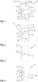
- Figure 1 shows a device 1 according to the invention, designated as a whole by 1.
- the device 1 has a housing 2 which has a protected interior 9.
- the device 1 according to the invention has Locks and/or decontamination areas commonly used for isolators or containments.
- the device 1 and/or the housing 2 may be movable.
- At least one object 3 is located on the floor, on the ceiling, on a vertical wall, and on an inclined wall, wherein the at least one object 3 is positioned on a receptacle 6 of a mover 4.
- the at least one mover 4 is magnetically coupled to a stator arrangement 5.
- FIG 1 shows that four stator assemblies 5, each composed of one or more stators, are positioned outside the protected interior space 9 on a vertical, horizontal, or inclined wall.
- a stator assembly 5 can also be positioned in the housing 2 and/or in a boundary wall 8 and/or between the housing 2 and the boundary wall 8.
- the at least one mover 4 can be operated passively, for example by integrated permanent magnets (not shown), or actively, for example by an integrated coil package (not shown), on the drive surface 7.
- the active operation of the at least one mover 4 can be realized by a preferably contactless movement, in particular a movement along the drive surface or with a component transverse to it, a rotation and/or a tilting, relative to the drive surface 7.
- the drive surface 7 forms the boundary wall 8 of the device 1.
- the device 1 according to the invention can additionally have conventional transport devices such as conveyor belts, star wheels and/or computing systems for moving the at least one object 3.
- a device 1 has a coupling area 10, which is incorporated into a vertical boundary wall 8 of a housing 2.
- the area of the coupling area 10 is smaller than the area of the vertical boundary wall 8.
- the vertical boundary wall 8 can have various process stations 15 positioned inside or outside the coupling area 10 and on the side of the protected interior 9 (not shown). These process stations 15 can be approached by at least one mover 4 for manipulating at least one object 3.
- the drive surface 7 is realized as a magnetically neutral separating layer 11, for example a separating layer 11 made of glass, stainless steel, gas-tight plastic or composite material.
- the coupling region 10 is positioned and stabilized on the housing 2 and/or the boundary wall 8 by magnetically neutral support components 12, for example bars and/or angles and/or profile rails and/or ribs and/or other stiffeners.
- stator arrangement 5 can also be connected to the housing 2 and/or the separating layer 11 by support components 12.
- a stator assembly 5 is mounted in a rack 13 outside the protected interior 9. For example, for repair and/or maintenance work, the stator assembly 5 can be moved away from a contact position near the boundary wall 8 by the rack 13, so that the stator assembly 5 is accessible.
- the rack 13 may have a drive (not shown) to drive individual tiles of the stator arrangement 5 and/or to move the stator arrangement 5 within one or between several drive surfaces 7.
- a stator arrangement 5 is arranged on a vertical wall.
- a mover 4 which holds at least one object 3 on a holder 6.
- a filling device 14 is permanently mounted above the mover 4 on the vertical wall, and a further process station 15 is permanently mounted below the mover 4.
- the mover 4 can move to the filling device 14 to fill the at least one object 3.
- the mover 4 can move with the at least one object 3 to the process station 15, which can preferably be a scale, in order to measure the fill level of the at least one object 3.
- the filling device 14 and/or the process station 15 can be positioned on a mover 4 (not shown). This allows the mover 4 to be moved relative to the filling device 14 and/or the process station 15.
- process station 15 and/or the filling device 14 could be arranged on a conventional movement system, in particular as already mentioned.
- a method for filling an object preferably a vial, a syringe, a carpoule and/or an ampoule or an injection bottle, can thus be carried out, which method could proceed as follows.
- a mover 4 moves at least one empty or partially filled object 3 to a scale in order to determine the empty weight of the to determine at least one unfilled or partially filled object 3.
- the mover 4 then moves the at least one unfilled or partially filled object 3 along a vertical drive surface 7 toward a filling device 14, by which the at least one unfilled or partially filled object 3 is filled.
- the mover 4 can be moved with the at least one filled object 3 to another process station 15 for further process steps, for example, back to the further scale.
- FIG. 5 A device 1 with two chambers 16, 23 is depicted.
- the two chambers 16, 23 are formed by an intermediate wall 17 and connected to one another via at least one small access opening 18.
- the stator arrangement 5 shown here is formed at the bottom of the device 1.
- At least one mover 4 can be moved by a horizontal movement through the at least one small access opening 18 between the two chambers 16, 23.
- a stator arrangement 5 can also be arranged on a vertical and/or inclined wall in order to move the at least one mover 4 between the at least two chambers 16, 23.
- At least one rack 13 with at least one stator arrangement 5 is positioned on a partition wall 17 between two chambers 16, 23.
- the at least one mover 4 can be moved vertically and/or horizontally on the partition wall 17.
- the at least one mover 4 can be moved in or between the at least two chambers 16, 23.
- Figure 7 depicts a device 1 with two chambers 16, 23, in which a process station 15 is mounted on a vertical wall of a first chamber 16.
- the process station 15 shown here extends through an access opening 18 into the second chamber 23, but in alternative embodiments can also extend into several chambers 16, 23.
- the stator arrangement 5 is enclosed in an intermediate wall 17.
- a mover 4 located in the second chamber 23 can move towards the process station 15 via the magnetic coupling with the stator arrangement 5, where processing of an object 3 can be carried out.
- the or a part of the process station 15 can be movable, for example movable within a chamber 16, 23 or between at least two chambers 16, 23.
- FIG. 8 Within the protected space 9 of the device 1, there is a mover 4 with a corresponding stator arrangement 5, wherein the stator arrangement 5 is enclosed on all sides by a tight and magnetically neutral enclosure 19.
- the enclosure 19, together with the stator arrangement 5, is robustly positioned in the protected interior space 9 by two anchors 20.
- the number of supporting anchors 20 can be configured alternatively, which is why an enclosure 19 can be positioned in the protected interior space 9 without, with one, or with more than two anchors 20.
- the casing 19, together with the mover 4 and stator arrangement 5, can be suspended and/or clamped into the protected interior 9.
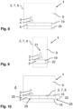
- Figure 9 shows a side view of a device 1 in which an object 3 is located on a mover 4 within a flow zone 21.
- filtered air is drawn from the ceiling into the protected
- the interior 9 is inserted to displace the air present therein.
- Figure 9 It can be seen that the mover 4 is magnetically coupled to a stator assembly 5, which is tightly enclosed by a tunnel 22.
- the casing 19 forming the tunnel 22 is made of magnetically neutral materials to ensure trouble-free use of the mover-stator application.
- racks 13 or other transport vehicles that enable the stator assembly 5 to be extended from the tunnel 22.
- Figure 10 shows a tunnel 22, as it is particularly in Figure 9 is shown in a front view.
- the drive surface 2, 7, 8 is formed by the casing 19 of the tunnel 22.
- the drive surface 2, 7, 9 can also be designed separately or independently of the tunnel 22 or its casing 19 within the protected interior space 9, so that the device 1 can be designed flexibly.
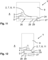
- the Tunnel 22 in Figs. 11 and 12 is accessible from both sides from the outside of the protected interior 9.
- the stators of the stator arrangement 5 can be brought into the outer space A via the accesses 25, in particular as with regard to Figure 9 as already described.
- the stators of the stator assembly 5 can be serviced without having to enter the protected interior 9 or contaminating it through manipulation.
- Such accesses 25 can also be formed in a profile body 24 as described below.
- the tunnel 22 is surrounded by the protected interior 9 along a full circumference running around its longitudinal extent.
- stator arrangement 5 is provided with an adjusting device 26 (cf. Figs. 13 and 14 ) so that it can be aligned if necessary.
- FIGS 11 1 (front view) and 12 (side view) show a device 1 with a profile body 24 located in the protected interior space 9, wherein the profile body 24 has the stator arrangement 5 and the separating layer 11, in particular wherein the film-like separating layer 11 is replaceably attached to the profile body 24.
- the film-like separating layer 11 is adhesively attached to adhesive surfaces of the profile body 24 and seals it.
- Figs. 13 and 14 show two variants of the structure Figs. 11 and 12 more detailed.
- the separating layer 11 which can be film-like for this purpose, is placed on an outer profile 29, for example made of sheet metal, of the profile body 24 and glued to it.
- the inner profile for example made of aluminum or plastic (e.g., glass-fiber-reinforced plastic), is arranged in the space 31 thus formed, which is connected to the outer space A via the base 24.
- This inner profile 28 accommodates the stator arrangement 5 and is placed on adjustment devices 26 in order to align an upper side of the stator arrangement 5 with an end of the outer profile 29.
- the separating layer 11 - also foil-like, for example - is formed by an inner profile preferably made of aluminum or plastic such as GRP or another magnetically neutral material 28 of the profile body 24.
- the separating layer 11 rests on the stator assembly 5, so that no air gap is created between the separating layer 11 and the stator assembly 5.
- the magnetic coupling of the mover 4 and the stator assembly 5 is particularly efficient and trouble-free.
- the profile body 24 according to the Figures 11 and 12 is inserted or placed in the protected interior 9 and has two feet 27 (see Figure 11 ), which form a connection to the exterior space A of the protected interior space 9, so that, for example, electrical components can advantageously be supplied to or removed from the profile body 24, in particular the stator arrangement 5.
- the two feet 27 advantageously serve to dissipate the waste heat produced by the stator arrangement 5. This prevents overheating of the device 1.
- connecting lines of the stator arrangement 5 can be routed into the exterior space A via the foot 24.
- the profile body 24 is supported by only one foot 27 or by more than two feet 27.
- the invention thus generally proposes a device 1 for manipulating an object 3, wherein the object 3 can be moved contactlessly on a drive surface 7 by at least one mover 4, which is magnetically coupled to a stator arrangement 5, wherein the drive surface 7 is Boundary wall 8 of a protected interior space 9.
- a flexible device 1 is preferably of interest in the food industry or pharmaceutical industry, but is not limited to these areas.
Landscapes
- Engineering & Computer Science (AREA)
- Mechanical Engineering (AREA)
- Robotics (AREA)
- Power Engineering (AREA)
- Combustion & Propulsion (AREA)
- Electromagnetism (AREA)
- Chemical & Material Sciences (AREA)
- Physics & Mathematics (AREA)
- Non-Mechanical Conveyors (AREA)
- Basic Packing Technique (AREA)
- Linear Motors (AREA)
- Filling Of Jars Or Cans And Processes For Cleaning And Sealing Jars (AREA)
- Supplying Of Containers To The Packaging Station (AREA)
Claims (18)
- Dispositif (1) pour la manipulation d'un objet (3), dans lequel l'objet (3) peut être déplacé sans contact sur une surface d'entraînement (7) par au moins un manipulateur (4) en couplage magnétique avec un dispositif de stator (5), dans lequel la surface d'entraînement (7) est conçue comme une délimitation étanche, en particulier comme une paroi de délimitation (8), d'un espace intérieur protégé (9), dans lequel une zone de couplage (10) du dispositif de stator (5) est fabriquée à partir d'une couche de séparation magnétiquement neutre (11) et dans lequel au moins un poste de traitement (15) est monté fixe ou sur le manipulateur (4) dans l'espace intérieur protégé (9).
- Dispositif (1) selon la revendication 1, caractérisé en ce que le dispositif de stator (5) est disposé à l'extérieur d'un espace intérieur protégé (9), en particulier sur une paroi de délimitation (8) de préférence verticale et/ou horizontale et/ou oblique, et/ou en ce que l'au moins un manipulateur (4) est disposé dans l'espace intérieur protégé (9) ou à l'extérieur de l'espace intérieur protégé (9).
- Dispositif (1) selon l'une des revendications précédentes, caractérisé en ce que la paroi de délimitation (8) de l'espace intérieur protégé (9) possède une zone de couplage (10) formée du dispositif de stator (5) et de l'au moins un manipulateur (4), l'aire à l'intérieur de la zone de couplage (10) pouvant en particulier être plus petite que l'aire de la paroi de délimitation (8).
- Dispositif (1) selon l'une des revendications précédentes, caractérisé en ce que la paroi de délimitation (8) est fabriquée à partir de la couche de séparation magnétiquement neutre (11), en particulier à partir d'une couche d'acier inoxydable et/ou de verre et/ou d'un matériau de synthèse imperméable au gaz et/ou d'un matériau composite, dont l'épaisseur est de préférence inférieure à 2 mm, et/ou en ce que la paroi de délimitation (8) et/ou la ou une zone de couplage (10) sont stabilisées par des composants portants (12), faits de préférence de matériau magnétiquement neutre.
- Dispositif (1) selon l'une des revendications précédentes, caractérisé en ce que le dispositif de stator (5) est monté dans au moins un châssis (13), l'au moins un châssis (13) étant supporté directement sur la paroi de délimitation (8) et/ou la ou une zone de couplage (10), et/ou pouvant être déplacé vers et à partir du lieu d'utilisation et/ou pouvant être déplacé sur le lieu d'utilisation entre une position de travail rapprochée de la paroi de délimitation (8) et une position éloignée de la paroi de délimitation (8).
- Dispositif (1) selon l'une des revendications précédentes, caractérisé en ce que la ou une paroi de délimitation (8) et/ou la ou une couche de séparation (11) peuvent être enlevées du dispositif (1).
- Dispositif (1) selon l'une des revendications précédentes, caractérisé en ce que l'espace intérieur protégé (9) possède au moins deux chambres (16, 23), les au moins deux chambres (16, 23) étant en particulier formées par une cloison (17) qui présente de préférence une petite ouverture d'accès (18) et/ou qui forme de préférence la paroi de délimitation (8).
- Dispositif (1) selon l'une des revendications précédentes, caractérisé en ce que l'au moins un poste de traitement (15), par exemple une installation de remplissage (14), est disposé dans la ou une zone de couplage (10) et/ou dans une chambre (16) et se trouve fixé dans une deuxième chambre (23).
- Dispositif (1) selon l'une des revendications 7 ou 8, caractérisé en ce que le dispositif de stator (5) est disposé sur au moins une paroi de délimitation (8) et/ou au moins une zone de couplage (10) et/ou deux parois voisines de l'espace intérieur protégé (9), de telle façon que l'au moins un manipulateur (4) puisse transporter l'au moins un objet (3) à l'intérieur des au moins deux chambres (16, 23) et/ou à travers l'au moins une petite ouverture d'accès (18) de la cloison (17) entre les au moins deux chambres (16, 23).
- Dispositif (1) selon l'une des revendications 7 à 9, caractérisé en ce que le dispositif de stator (5) est disposé de préférence verticalement à l'intérieur de l'au moins une cloison (17) entre les au moins deux chambres (16, 23).
- Dispositif (1) selon les revendications 7 à 10, caractérisé en ce que le dispositif de stator (5) est monté dans l'au moins une cloison (17) dans au moins un châssis (13).
- Dispositif (1) selon l'une des revendications précédentes, caractérisé en ce que l'espace intérieur protégé (9) comporte au moins une zone parcourue par un flux (21), la surface d'entraînement (7) étant en particulier orientée de telle façon que l'au moins un manipulateur (4) puisse être déplacé dans la zone (21) et/ou à l'intérieur de la zone (21).
- Dispositif (1) selon l'une des revendications précédentes, caractérisé en ce que le dispositif de stator (5) est entouré par un tunnel (22) hermétique par rapport à l'espace intérieur (9), la surface d'entraînement (7) étant formée par une enveloppe (19) du tunnel (22) et la surface d'entraînement (7) étant formée à l'intérieur de l'espace intérieur protégé (9) indépendamment de l'enveloppe (19).
- Dispositif (1) selon la revendication 13, caractérisé en ce que le tunnel (22) est accessible d'un côté ou des deux côtés par l'extérieur de l'espace intérieur protégé (9) et/ou en ce que le tunnel (22) est entouré par l'espace intérieur protégé (9) le long de toute une circonférence qui s'étend dans le sens de la longueur.
- Dispositif (1) selon l'une des revendications précédentes, caractérisé en ce que l'espace intérieur protégé (9) comporte un corps profilé (24), lequel corps profilé (24) comporte le dispositif de stator (5) et la couche de séparation (11), la couche de séparation (11), de préférence en forme de film, étant de préférence fixée de façon interchangeable sur le corps profilé (24).
- Dispositif (1) selon l'une des revendications 13 à 15, caractérisé en ce que le tunnel (22) et/ou le corps profilé (24) forment des accès (25) à l'extérieur de l'espace intérieur protégé (9).
- Procédé pour le remplissage d'au moins un objet (3) avec un dispositif selon l'une des revendications précédentes, caractérisé en ce que l'au moins un objet (3) est déplacé par un manipulateur (4) sur une surface d'entraînement (7) de l'espace intérieur protégé (9) vers un poste de traitement (15), de préférence une installation de remplissage (14), et déplacé à travers l'installation de remplissage (14), laquelle installation de remplissage (14) est positionnée dans l'espace intérieur protégé, en particulier sur la surface d'entraînement (7) ou sur un autre manipulateur (4).
- Utilisation d'une paroi de délimitation (8) d'un espace intérieur protégé (9) d'un dispositif (1) selon l'une des revendications 1 à 16 comme surface d'entraînement (7) d'au moins un manipulateur (4) qui est couplé à un dispositif de stator (5).
Applications Claiming Priority (2)
| Application Number | Priority Date | Filing Date | Title |
|---|---|---|---|
| EP21180412.5A EP4106160A1 (fr) | 2021-06-18 | 2021-06-18 | Dispositif de manipulation d'un objet, procédé de remplissage d'un objet et utilisation correspondante |
| PCT/EP2022/066602 WO2022263651A1 (fr) | 2021-06-18 | 2022-06-17 | Dispositif de manipulation d'objet, procédé de remplissage d'objet et utilisation correspondante |
Publications (3)
| Publication Number | Publication Date |
|---|---|
| EP4200962A1 EP4200962A1 (fr) | 2023-06-28 |
| EP4200962C0 EP4200962C0 (fr) | 2025-03-19 |
| EP4200962B1 true EP4200962B1 (fr) | 2025-03-19 |
Family
ID=76999556
Family Applications (2)
| Application Number | Title | Priority Date | Filing Date |
|---|---|---|---|
| EP21180412.5A Withdrawn EP4106160A1 (fr) | 2021-06-18 | 2021-06-18 | Dispositif de manipulation d'un objet, procédé de remplissage d'un objet et utilisation correspondante |
| EP22733459.6A Active EP4200962B1 (fr) | 2021-06-18 | 2022-06-17 | Dispositif de manipulation d'un objet, procédé de remplissage d'un objet et utilisation correspondante |
Family Applications Before (1)
| Application Number | Title | Priority Date | Filing Date |
|---|---|---|---|
| EP21180412.5A Withdrawn EP4106160A1 (fr) | 2021-06-18 | 2021-06-18 | Dispositif de manipulation d'un objet, procédé de remplissage d'un objet et utilisation correspondante |
Country Status (11)
| Country | Link |
|---|---|
| US (1) | US12116214B2 (fr) |
| EP (2) | EP4106160A1 (fr) |
| JP (1) | JP7562712B2 (fr) |
| KR (1) | KR102788710B1 (fr) |
| CN (1) | CN115812023B (fr) |
| AU (1) | AU2022295098B2 (fr) |
| BR (1) | BR112022024106A2 (fr) |
| CA (1) | CA3183285A1 (fr) |
| ES (1) | ES3033207T3 (fr) |
| HU (1) | HUE071859T2 (fr) |
| WO (1) | WO2022263651A1 (fr) |
Families Citing this family (10)
| Publication number | Priority date | Publication date | Assignee | Title |
|---|---|---|---|---|
| IT202200000254A1 (it) * | 2022-01-11 | 2023-07-11 | Ima Spa | Apparecchiatura per trasportare oggetti. |
| DE102022118418A1 (de) * | 2022-07-22 | 2024-01-25 | Tt Innovation Ag | Montiervorrichtung |
| IT202200026922A1 (it) * | 2022-12-28 | 2024-06-28 | Ima Spa | Apparecchiatura e procedimento per movimentare automaticamente oggetti nell’ambito di un ambiente con atmosfera controllata. |
| DE102023118510A1 (de) | 2023-07-13 | 2025-01-16 | Tt Innovation Ag | Vorrichtung zur Manipulation eines Gegenstandes, Verfahren zur Befüllung eines Gegenstandes und korrespondierende Verwendung |
| EP4582529B1 (fr) | 2024-01-08 | 2026-03-18 | BdelloRob GmbH | Incubateur |
| EP4610178A1 (fr) * | 2024-02-29 | 2025-09-03 | Rotzinger PharmaPack GmbH | Installation de production automatisée et chaîne de production |
| US12685078B2 (en) * | 2024-04-30 | 2026-07-14 | Applied Materials, Inc. | Semiconductor process equipment |
| DE102024118533A1 (de) * | 2024-07-01 | 2026-01-08 | Bausch + Ströbel SE + Co. KG | Planartransportsystem für eine Anlage zum Verarbeiten pharmazeutischer Behälter und Anlage zum Verarbeiten pharmazeutischer Behälter |
| WO2026025198A2 (fr) * | 2024-08-02 | 2026-02-05 | Planar Motor Incorporated | Dispositif de stator pour système de déplacement |
| EP4686678A1 (fr) * | 2024-08-02 | 2026-02-04 | TT Innovation AG | Environnement contrôlé avec un dispositif de transport, utilisation de moyens de serrage, utilisation d'au moins un élément d'étanchéité, utilisation d'une unité de transport |
Citations (22)
| Publication number | Priority date | Publication date | Assignee | Title |
|---|---|---|---|---|
| JPH01116065A (ja) * | 1987-10-30 | 1989-05-09 | Hitachi Ltd | 真空機器への動力伝達機構 |
| JPH07117849A (ja) | 1993-10-22 | 1995-05-09 | Ebara Corp | 磁気浮上搬送装置 |
| US6114781A (en) | 1999-02-26 | 2000-09-05 | Nikon Corporation | Cooling system for a linear or planar motor |
| US20090033901A1 (en) | 2007-08-01 | 2009-02-05 | Canon Kabushiki Kaisha | Driving apparatus and exposure apparatus using the same and device manufacturing method |
| DE102008023339A1 (de) | 2008-05-13 | 2009-12-03 | Mecatronix Gmbh | Aktive magnetische Lagerung mit integrierter Elektronik, Sensorik sowie Aktuatorik und Verkabelung innerhalb eines Bus-Systems |
| EP2420450A1 (fr) | 2010-08-17 | 2012-02-22 | Aseptic Technologies | Appareil de remplissage d'un produit dans un conteneur dans des conditions aseptiques |
| DE102014102630A1 (de) | 2014-02-27 | 2015-08-27 | Krones Ag | Vorrichtung und Verfahren zum Transport von Behältern innerhalb von Isolatormaschinen |
| DE102014214693A1 (de) | 2014-07-25 | 2016-01-28 | Robert Bosch Gmbh | Vorrichtung zum Wiegen eines Behältnisses |
| DE102014214697A1 (de) | 2014-07-25 | 2016-01-28 | Robert Bosch Gmbh | Vorrichtung zum Befüllen eines Behältnisses |
| DE102014214694A1 (de) | 2014-07-25 | 2016-01-28 | Robert Bosch Gmbh | Vorrichtung zum Verschließen eines Behältnisses |
| DE102014214696A1 (de) | 2014-07-25 | 2016-01-28 | Robert Bosch Gmbh | Vorrichtung zum Transport eines Behältnisses relativ zu einer Füllstation |
| US20160218029A1 (en) | 2015-01-23 | 2016-07-28 | Applied Materials, Inc. | Semiconductor process equipment |
| DE102015209610A1 (de) | 2015-05-26 | 2016-12-01 | Robert Bosch Gmbh | Transportvorrichtung |
| DE102016224951A1 (de) | 2016-12-14 | 2018-06-14 | Robert Bosch Gmbh | Beförderungsvorrichtung mit einem Stator zur kontrollierten Beförderung eines Transportkörpers relativ zum Stator |
| DE102017222456A1 (de) | 2017-12-12 | 2019-06-13 | Festo Ag & Co. Kg | Arbeitsraum und Reinraumsystem |
| DE102017131436A1 (de) | 2017-12-29 | 2019-07-04 | Sig Technology Ag | Verpackungseinrichtung und Verfahren zum Betreiben einer Verpackungseinrichtung |
| DE102018006259A1 (de) | 2018-06-14 | 2019-12-19 | Robert Bosch Gmbh | Beförderungsvorrichtung zum Befördern mindestens eines Wafers |
| WO2020057739A1 (fr) | 2018-09-19 | 2020-03-26 | Applied Materials, Inc. | Système de lévitation magnétique, base d'un système de lévitation magnétique, système à vide et procédé de maintien et de déplacement sans contact d'un support dans une chambre à vide |
| WO2021115545A1 (fr) | 2019-12-09 | 2021-06-17 | Sidel Participations | Machine permettant de déplacer et manipuler des contenants conçus pour contenir un produit fluide |
| EP3945046A1 (fr) * | 2020-07-31 | 2022-02-02 | Krones Ag | Installation de traitement des récipients |
| WO2022200094A1 (fr) | 2021-03-25 | 2022-09-29 | Robert Bosch Gmbh | Dispositif de transport sans contact |
| WO2022238429A1 (fr) * | 2021-05-11 | 2022-11-17 | Beckhoff Automation Gmbh | Rotor conçu pour un système d'entraînement planaire et système d'entraînement planaire |
Family Cites Families (16)
| Publication number | Priority date | Publication date | Assignee | Title |
|---|---|---|---|---|
| US4731260A (en) | 1984-12-18 | 1988-03-15 | American Hospital Supply Corporation | Hydrophobic filter material and method |
| CN86201516U (zh) * | 1986-03-28 | 1987-06-10 | 苏州市粮油中心化验室 | 电磁式碾磨器 |
| US5126648A (en) * | 1990-03-22 | 1992-06-30 | Megamation Incorporated | High resolution piggyback linear motor design for placement systems and the like |
| JPH05330654A (ja) * | 1992-05-26 | 1993-12-14 | Ntn Corp | エアスライド装置 |
| JPH0812077A (ja) | 1994-07-05 | 1996-01-16 | Ulvac Japan Ltd | 真空装置用磁気浮上搬送装置 |
| US6147421A (en) * | 1998-11-16 | 2000-11-14 | Nikon Corporation | Platform positionable in at least three degrees of freedom by interaction with coils |
| US6208045B1 (en) * | 1998-11-16 | 2001-03-27 | Nikon Corporation | Electric motors and positioning devices having moving magnet arrays and six degrees of freedom |
| KR100827738B1 (ko) * | 2004-12-20 | 2008-05-07 | 고쿠리츠 다이가쿠 호진 큐슈 코교 다이가쿠 | 초전도 자기 부상에 의한 비접촉 반송 장치 |
| JP3117063U (ja) | 2005-09-26 | 2006-01-05 | 共和真空技術株式会社 | 食品・薬品等の密閉式粉末充填装置における粉末体の供給装置 |
| DE102011075176A1 (de) | 2011-05-03 | 2012-11-08 | Robert Bosch Gmbh | Verfahren zum Betreiben eines elektromagnetischen Transfersystems und Transfersystem |
| US11014696B2 (en) | 2017-07-12 | 2021-05-25 | Vanrx Pharmasystems Inc. | Purgeable pharmaceutical fill needle |
| JP6035590B2 (ja) * | 2014-05-27 | 2016-11-30 | 株式会社国際電気通信基礎技術研究所 | アクチュエータ装置、ヒューマノイド型ロボットおよびパワーアシスト装置 |
| CN114025926B (zh) * | 2019-02-14 | 2024-10-08 | 柿子技术公司 | 模块化材料处理机器人平台 |
| DE102019215745B4 (de) * | 2019-10-14 | 2022-03-03 | Festo Se & Co. Kg | Bearbeitungseinrichtung |
| CN110743882B (zh) * | 2019-10-28 | 2021-11-23 | 衡阳海之波商贸有限公司 | 一种垂直运送式玻璃清洁送料机构 |
| CN112841512A (zh) | 2021-02-06 | 2021-05-28 | 郑州科技学院 | 一种高纤馒头制备设备及其制备工艺 |
-
2021
- 2021-06-18 EP EP21180412.5A patent/EP4106160A1/fr not_active Withdrawn
-
2022
- 2022-06-17 HU HUE22733459A patent/HUE071859T2/hu unknown
- 2022-06-17 KR KR1020227041667A patent/KR102788710B1/ko active Active
- 2022-06-17 JP JP2022578699A patent/JP7562712B2/ja active Active
- 2022-06-17 WO PCT/EP2022/066602 patent/WO2022263651A1/fr not_active Ceased
- 2022-06-17 AU AU2022295098A patent/AU2022295098B2/en active Active
- 2022-06-17 CA CA3183285A patent/CA3183285A1/fr active Pending
- 2022-06-17 BR BR112022024106A patent/BR112022024106A2/pt unknown
- 2022-06-17 EP EP22733459.6A patent/EP4200962B1/fr active Active
- 2022-06-17 CN CN202280005336.XA patent/CN115812023B/zh active Active
- 2022-06-17 ES ES22733459T patent/ES3033207T3/es active Active
- 2022-06-17 US US18/008,735 patent/US12116214B2/en active Active
Patent Citations (23)
| Publication number | Priority date | Publication date | Assignee | Title |
|---|---|---|---|---|
| JPH01116065A (ja) * | 1987-10-30 | 1989-05-09 | Hitachi Ltd | 真空機器への動力伝達機構 |
| JPH07117849A (ja) | 1993-10-22 | 1995-05-09 | Ebara Corp | 磁気浮上搬送装置 |
| US6114781A (en) | 1999-02-26 | 2000-09-05 | Nikon Corporation | Cooling system for a linear or planar motor |
| US20090033901A1 (en) | 2007-08-01 | 2009-02-05 | Canon Kabushiki Kaisha | Driving apparatus and exposure apparatus using the same and device manufacturing method |
| DE102008023339A1 (de) | 2008-05-13 | 2009-12-03 | Mecatronix Gmbh | Aktive magnetische Lagerung mit integrierter Elektronik, Sensorik sowie Aktuatorik und Verkabelung innerhalb eines Bus-Systems |
| EP2420450A1 (fr) | 2010-08-17 | 2012-02-22 | Aseptic Technologies | Appareil de remplissage d'un produit dans un conteneur dans des conditions aseptiques |
| DE102014102630A1 (de) | 2014-02-27 | 2015-08-27 | Krones Ag | Vorrichtung und Verfahren zum Transport von Behältern innerhalb von Isolatormaschinen |
| DE102014214693A1 (de) | 2014-07-25 | 2016-01-28 | Robert Bosch Gmbh | Vorrichtung zum Wiegen eines Behältnisses |
| DE102014214697A1 (de) | 2014-07-25 | 2016-01-28 | Robert Bosch Gmbh | Vorrichtung zum Befüllen eines Behältnisses |
| DE102014214694A1 (de) | 2014-07-25 | 2016-01-28 | Robert Bosch Gmbh | Vorrichtung zum Verschließen eines Behältnisses |
| DE102014214696A1 (de) | 2014-07-25 | 2016-01-28 | Robert Bosch Gmbh | Vorrichtung zum Transport eines Behältnisses relativ zu einer Füllstation |
| US20160218029A1 (en) | 2015-01-23 | 2016-07-28 | Applied Materials, Inc. | Semiconductor process equipment |
| DE102015209610A1 (de) | 2015-05-26 | 2016-12-01 | Robert Bosch Gmbh | Transportvorrichtung |
| DE102016224951A1 (de) | 2016-12-14 | 2018-06-14 | Robert Bosch Gmbh | Beförderungsvorrichtung mit einem Stator zur kontrollierten Beförderung eines Transportkörpers relativ zum Stator |
| DE102017222456A1 (de) | 2017-12-12 | 2019-06-13 | Festo Ag & Co. Kg | Arbeitsraum und Reinraumsystem |
| DE102017131436A1 (de) | 2017-12-29 | 2019-07-04 | Sig Technology Ag | Verpackungseinrichtung und Verfahren zum Betreiben einer Verpackungseinrichtung |
| DE102018006259A1 (de) | 2018-06-14 | 2019-12-19 | Robert Bosch Gmbh | Beförderungsvorrichtung zum Befördern mindestens eines Wafers |
| WO2020057739A1 (fr) | 2018-09-19 | 2020-03-26 | Applied Materials, Inc. | Système de lévitation magnétique, base d'un système de lévitation magnétique, système à vide et procédé de maintien et de déplacement sans contact d'un support dans une chambre à vide |
| WO2021115545A1 (fr) | 2019-12-09 | 2021-06-17 | Sidel Participations | Machine permettant de déplacer et manipuler des contenants conçus pour contenir un produit fluide |
| EP3945046A1 (fr) * | 2020-07-31 | 2022-02-02 | Krones Ag | Installation de traitement des récipients |
| WO2022200094A1 (fr) | 2021-03-25 | 2022-09-29 | Robert Bosch Gmbh | Dispositif de transport sans contact |
| WO2022238429A1 (fr) * | 2021-05-11 | 2022-11-17 | Beckhoff Automation Gmbh | Rotor conçu pour un système d'entraînement planaire et système d'entraînement planaire |
| EP4338261A1 (fr) * | 2021-05-11 | 2024-03-20 | Beckhoff Automation GmbH | Rotor conçu pour un système d'entraînement planaire et système d'entraînement planaire |
Non-Patent Citations (4)
| Title |
|---|
| ANONYMOUS: "XPlanar Planarmotorantriebssystem - Original-Betriebsanleitung", BECKHOFF, 6 January 2021 (2021-01-06), XP093355216 |
| D16 - BEIBLATT ZU ANLAGE 19 - VIDEOLINK |
| JOHNSON JEFF: "XPlanar Transports Workpiece during Plasma Surface Treatment Process", BECKHOFF AUTOMATION, 5 April 2021 (2021-04-05), XP093355208, Retrieved from the Internet <URL:https://www.blog.beckhoffus.com/post/xplanar-transports-workpiece-during-plasma-surface-treatment-process> |
| N N: "Flying Motion XPlanar", 1 November 2018 (2018-11-01), pages 1 - 28, XP055668904, Retrieved from the Internet <URL:https://download.beckhoff.com/download/Document/catalog/Beckhoff_XPlanar_d.pdf> |
Also Published As
| Publication number | Publication date |
|---|---|
| AU2022295098A1 (en) | 2023-02-02 |
| US20240228184A1 (en) | 2024-07-11 |
| WO2022263651A1 (fr) | 2022-12-22 |
| BR112022024106A2 (pt) | 2024-01-16 |
| CN115812023A (zh) | 2023-03-17 |
| US12116214B2 (en) | 2024-10-15 |
| EP4106160A1 (fr) | 2022-12-21 |
| EP4200962A1 (fr) | 2023-06-28 |
| CN115812023B (zh) | 2025-05-13 |
| HUE071859T2 (hu) | 2025-09-28 |
| EP4200962C0 (fr) | 2025-03-19 |
| CA3183285A1 (fr) | 2022-12-18 |
| JP2023535276A (ja) | 2023-08-17 |
| ES3033207T3 (en) | 2025-07-31 |
| KR102788710B1 (ko) | 2025-03-28 |
| KR20230003140A (ko) | 2023-01-05 |
| AU2022295098B2 (en) | 2023-09-21 |
| JP7562712B2 (ja) | 2024-10-07 |
Similar Documents
| Publication | Publication Date | Title |
|---|---|---|
| EP4200962A1 (fr) | Dispositif de manipulation d'objet, procédé de remplissage d'objet et utilisation correspondante | |
| EP2504244B1 (fr) | Dispositif pour le traitement aseptique ou stérile de moyens d'emballage | |
| EP3172134B1 (fr) | Dispositif servant à transporter un contenant par rapport à un poste de remplissage | |
| DE69400003T2 (de) | Anlage und Verfahren zur Übergabe von durch Schwerkraft fliessende Produkte. | |
| EP3973623A1 (fr) | Agencement de modules de stator pour un système d'entraînement planaire | |
| DE102005039453B4 (de) | Bearbeitungsanlage modularen Aufbaus für flächige Substrate | |
| EP0267507A2 (fr) | Conteneur pour la manipulation d'éléments semi-conducteurs | |
| DE102012110108A1 (de) | Vorrichtung zur Außensterilisation von Kunststoffvorformlingen | |
| EP2094313B1 (fr) | Installation de stérilisation d'objets au moyen d'une source de rayonnement | |
| DE102016004335B4 (de) | Transporteinrichtung und Verfahren zum Transport von Objekten von Arbeitsstation zu Arbeitsstation einer Produktionsanlage und Produktionsanlage zur Herstellung von Produkten mit einer derartigen Transporteinrichtung | |
| WO2026008355A1 (fr) | Système de transport plan pour une installation de traitement de récipients pharmaceutiques et installation de traitement de récipients pharmaceutiques | |
| DE69600136T2 (de) | Uebergabeanlage von Behältern für durch Schwerkraft fliessende Produkte | |
| DE102024118524A1 (de) | Aufnahmevorrichtung für pharmazeutische Behälter, planares Transportsystem und Anlage zum Verarbeiten pharmazeutischer Behälter | |
| EP3056440A1 (fr) | Porte-objet et installation d'emballage | |
| EP4463256B1 (fr) | Dispositif de transfert, procédé et utilisation d'un dispositif de transfert pour transférer au moins un élément fonctionnel dans une chambre de traitement | |
| DE102023118510A1 (de) | Vorrichtung zur Manipulation eines Gegenstandes, Verfahren zur Befüllung eines Gegenstandes und korrespondierende Verwendung | |
| DE102015100637B4 (de) | Vorrichtung zum automatischen Durchführen chemischer und biologischer Verfahren in Gefäßplatten | |
| DE102013016597A1 (de) | System zum Be- und Entladen von Reinraumanlagen mit großflächigen Substraten | |
| DE102022109268A1 (de) | Isolator | |
| DE102015102143A1 (de) | Reinraum-Zuführsystem, Verfahren zum Austausch von zumindest einer Komponente, Stufenförderer | |
| EP4306272A1 (fr) | Dispositif de manipulation de produits à transporter à l'intérieur d'un système de barrière | |
| WO2026027494A1 (fr) | Environnement contrôlé présentant un dispositif de transport, utilisation de moyens de serrage, utilisation d'au moins un élément d'étanchéité, utilisation d'une unité de transport | |
| EP4445921B1 (fr) | Procédé pour introduire des articles d'un emballage dans la chambre de traitement d'une enceinte de confinement dans des conditions aseptiques et dispositif de sas | |
| WO2026008372A1 (fr) | Système de transport plan et installation de traitement de récipients pharmaceutiques avec un système de transport plan | |
| EP4558315A2 (fr) | Dispositif de montage |
Legal Events
| Date | Code | Title | Description |
|---|---|---|---|
| STAA | Information on the status of an ep patent application or granted ep patent |
Free format text: STATUS: UNKNOWN |
|
| STAA | Information on the status of an ep patent application or granted ep patent |
Free format text: STATUS: THE INTERNATIONAL PUBLICATION HAS BEEN MADE |
|
| PUAI | Public reference made under article 153(3) epc to a published international application that has entered the european phase |
Free format text: ORIGINAL CODE: 0009012 |
|
| STAA | Information on the status of an ep patent application or granted ep patent |
Free format text: STATUS: REQUEST FOR EXAMINATION WAS MADE |
|
| 17P | Request for examination filed |
Effective date: 20230321 |
|
| AK | Designated contracting states |
Kind code of ref document: A1 Designated state(s): AL AT BE BG CH CY CZ DE DK EE ES FI FR GB GR HR HU IE IS IT LI LT LU LV MC MK MT NL NO PL PT RO RS SE SI SK SM TR |
|
| STAA | Information on the status of an ep patent application or granted ep patent |
Free format text: STATUS: EXAMINATION IS IN PROGRESS |
|
| 17Q | First examination report despatched |
Effective date: 20240508 |
|
| DAV | Request for validation of the european patent (deleted) | ||
| DAX | Request for extension of the european patent (deleted) | ||
| GRAP | Despatch of communication of intention to grant a patent |
Free format text: ORIGINAL CODE: EPIDOSNIGR1 |
|
| STAA | Information on the status of an ep patent application or granted ep patent |
Free format text: STATUS: GRANT OF PATENT IS INTENDED |
|
| RIC1 | Information provided on ipc code assigned before grant |
Ipc: B65G 54/02 20060101ALI20241217BHEP Ipc: B25J 21/00 20060101ALI20241217BHEP Ipc: B25J 9/12 20060101ALI20241217BHEP Ipc: H02K 41/03 20060101AFI20241217BHEP |
|
| GRAS | Grant fee paid |
Free format text: ORIGINAL CODE: EPIDOSNIGR3 |
|
| INTG | Intention to grant announced |
Effective date: 20250113 |
|
| GRAA | (expected) grant |
Free format text: ORIGINAL CODE: 0009210 |
|
| STAA | Information on the status of an ep patent application or granted ep patent |
Free format text: STATUS: THE PATENT HAS BEEN GRANTED |
|
| AK | Designated contracting states |
Kind code of ref document: B1 Designated state(s): AL AT BE BG CH CY CZ DE DK EE ES FI FR GB GR HR HU IE IS IT LI LT LU LV MC MK MT NL NO PL PT RO RS SE SI SK SM TR |
|
| REG | Reference to a national code |
Ref country code: GB Ref legal event code: FG4D Free format text: NOT ENGLISH |
|
| REG | Reference to a national code |
Ref country code: CH Ref legal event code: EP |
|
| REG | Reference to a national code |
Ref country code: DE Ref legal event code: R096 Ref document number: 502022003278 Country of ref document: DE |
|
| REG | Reference to a national code |
Ref country code: IE Ref legal event code: FG4D Free format text: LANGUAGE OF EP DOCUMENT: GERMAN |
|
| U01 | Request for unitary effect filed |
Effective date: 20250416 |
|
| U07 | Unitary effect registered |
Designated state(s): AT BE BG DE DK EE FI FR IT LT LU LV MT NL PT RO SE SI Effective date: 20250424 |
|
| PG25 | Lapsed in a contracting state [announced via postgrant information from national office to epo] |
Ref country code: RS Free format text: LAPSE BECAUSE OF FAILURE TO SUBMIT A TRANSLATION OF THE DESCRIPTION OR TO PAY THE FEE WITHIN THE PRESCRIBED TIME-LIMIT Effective date: 20250619 |
|
| PG25 | Lapsed in a contracting state [announced via postgrant information from national office to epo] |
Ref country code: NO Free format text: LAPSE BECAUSE OF FAILURE TO SUBMIT A TRANSLATION OF THE DESCRIPTION OR TO PAY THE FEE WITHIN THE PRESCRIBED TIME-LIMIT Effective date: 20250619 |
|
| PG25 | Lapsed in a contracting state [announced via postgrant information from national office to epo] |
Ref country code: HR Free format text: LAPSE BECAUSE OF FAILURE TO SUBMIT A TRANSLATION OF THE DESCRIPTION OR TO PAY THE FEE WITHIN THE PRESCRIBED TIME-LIMIT Effective date: 20250319 |
|
| PG25 | Lapsed in a contracting state [announced via postgrant information from national office to epo] |
Ref country code: GR Free format text: LAPSE BECAUSE OF FAILURE TO SUBMIT A TRANSLATION OF THE DESCRIPTION OR TO PAY THE FEE WITHIN THE PRESCRIBED TIME-LIMIT Effective date: 20250620 |
|
| U20 | Renewal fee for the european patent with unitary effect paid |
Year of fee payment: 4 Effective date: 20250623 |
|
| REG | Reference to a national code |
Ref country code: ES Ref legal event code: FG2A Ref document number: 3033207 Country of ref document: ES Kind code of ref document: T3 Effective date: 20250731 |
|
| REG | Reference to a national code |
Ref country code: HU Ref legal event code: AG4A Ref document number: E071859 Country of ref document: HU |
|
| PG25 | Lapsed in a contracting state [announced via postgrant information from national office to epo] |
Ref country code: SM Free format text: LAPSE BECAUSE OF FAILURE TO SUBMIT A TRANSLATION OF THE DESCRIPTION OR TO PAY THE FEE WITHIN THE PRESCRIBED TIME-LIMIT Effective date: 20250319 |
|
| PGFP | Annual fee paid to national office [announced via postgrant information from national office to epo] |
Ref country code: ES Payment date: 20250718 Year of fee payment: 4 |
|
| PG25 | Lapsed in a contracting state [announced via postgrant information from national office to epo] |
Ref country code: PL Free format text: LAPSE BECAUSE OF FAILURE TO SUBMIT A TRANSLATION OF THE DESCRIPTION OR TO PAY THE FEE WITHIN THE PRESCRIBED TIME-LIMIT Effective date: 20250319 |
|
| PGFP | Annual fee paid to national office [announced via postgrant information from national office to epo] |
Ref country code: CH Payment date: 20250701 Year of fee payment: 4 |
|
| PG25 | Lapsed in a contracting state [announced via postgrant information from national office to epo] |
Ref country code: CZ Free format text: LAPSE BECAUSE OF FAILURE TO SUBMIT A TRANSLATION OF THE DESCRIPTION OR TO PAY THE FEE WITHIN THE PRESCRIBED TIME-LIMIT Effective date: 20250319 |
|
| PG25 | Lapsed in a contracting state [announced via postgrant information from national office to epo] |
Ref country code: SK Free format text: LAPSE BECAUSE OF FAILURE TO SUBMIT A TRANSLATION OF THE DESCRIPTION OR TO PAY THE FEE WITHIN THE PRESCRIBED TIME-LIMIT Effective date: 20250319 |
|
| PG25 | Lapsed in a contracting state [announced via postgrant information from national office to epo] |
Ref country code: IS Free format text: LAPSE BECAUSE OF FAILURE TO SUBMIT A TRANSLATION OF THE DESCRIPTION OR TO PAY THE FEE WITHIN THE PRESCRIBED TIME-LIMIT Effective date: 20250719 |
|
| PLBI | Opposition filed |
Free format text: ORIGINAL CODE: 0009260 |
|
| REG | Reference to a national code |
Ref country code: CH Ref legal event code: L11 Free format text: ST27 STATUS EVENT CODE: U-0-0-L10-L11 (AS PROVIDED BY THE NATIONAL OFFICE) Effective date: 20251224 |
|
| PLAB | Opposition data, opponent's data or that of the opponent's representative modified |
Free format text: ORIGINAL CODE: 0009299OPPO |
|
| PLBI | Opposition filed |
Free format text: ORIGINAL CODE: 0009260 |
|
| REG | Reference to a national code |
Ref country code: CH Ref legal event code: L10 Free format text: ST27 STATUS EVENT CODE: U-0-0-L10-L00 (AS PROVIDED BY THE NATIONAL OFFICE) Effective date: 20251231 |
|
| PLAX | Notice of opposition and request to file observation + time limit sent |
Free format text: ORIGINAL CODE: EPIDOSNOBS2 |
|
| RAP4 | Party data changed (patent owner data changed or rights of a patent transferred) |
Owner name: TT INNOVATION AG |
|
| U1H | Name or address of the proprietor changed after the registration of the unitary effect |
Owner name: TT INNOVATION AG; CH |
|
| 26 | Opposition filed |
Opponent name: GROSSE VON HIRSCHHAUSEN PATENTDIENST GMBH Effective date: 20251218 |
|
| 26 | Opposition filed |
Opponent name: BOSCH REXROTH AG Effective date: 20251219 |
|
| R26 | Opposition filed (corrected) |
Opponent name: GROSSE VON HIRSCHHAUSEN PATENTDIENST GMBH Effective date: 20251218 |
|
| PG25 | Lapsed in a contracting state [announced via postgrant information from national office to epo] |
Ref country code: MC Free format text: LAPSE BECAUSE OF FAILURE TO SUBMIT A TRANSLATION OF THE DESCRIPTION OR TO PAY THE FEE WITHIN THE PRESCRIBED TIME-LIMIT Effective date: 20250319 |
|
| PLBB | Reply of patent proprietor to notice(s) of opposition received |
Free format text: ORIGINAL CODE: EPIDOSNOBS3 |
|
| REG | Reference to a national code |
Ref country code: CH Ref legal event code: U11 Free format text: ST27 STATUS EVENT CODE: U-0-0-U10-U11 (AS PROVIDED BY THE NATIONAL OFFICE) Effective date: 20260701 |
|
| PGFP | Annual fee paid to national office [announced via postgrant information from national office to epo] |
Ref country code: GB Payment date: 20260623 Year of fee payment: 5 |
|
| PGFP | Annual fee paid to national office [announced via postgrant information from national office to epo] |
Ref country code: HU Payment date: 20260611 Year of fee payment: 5 Ref country code: IE Payment date: 20260629 Year of fee payment: 5 |
|
| U20 | Renewal fee for the european patent with unitary effect paid |
Year of fee payment: 5 Effective date: 20260630 |
|
| PG25 | Lapsed in a contracting state [announced via postgrant information from national office to epo] |
Ref country code: CY Free format text: LAPSE BECAUSE OF FAILURE TO SUBMIT A TRANSLATION OF THE DESCRIPTION OR TO PAY THE FEE WITHIN THE PRESCRIBED TIME-LIMIT Effective date: 20250319 |