EP4201166A1 - Outil de travail du sol - Google Patents
Outil de travail du sol Download PDFInfo
- Publication number
- EP4201166A1 EP4201166A1 EP22214628.4A EP22214628A EP4201166A1 EP 4201166 A1 EP4201166 A1 EP 4201166A1 EP 22214628 A EP22214628 A EP 22214628A EP 4201166 A1 EP4201166 A1 EP 4201166A1
- Authority
- EP
- European Patent Office
- Prior art keywords
- soil
- unit
- tillage
- working
- soil cultivation
- Prior art date
- Legal status (The legal status is an assumption and is not a legal conclusion. Google has not performed a legal analysis and makes no representation as to the accuracy of the status listed.)
- Granted
Links
Images

Classifications
-
- A—HUMAN NECESSITIES
- A01—AGRICULTURE; FORESTRY; ANIMAL HUSBANDRY; HUNTING; TRAPPING; FISHING
- A01B—SOIL WORKING IN AGRICULTURE OR FORESTRY; PARTS, DETAILS, OR ACCESSORIES OF AGRICULTURAL MACHINES OR IMPLEMENTS, IN GENERAL
- A01B49/00—Combined machines
- A01B49/02—Combined machines with two or more soil-working tools of different kind
- A01B49/027—Combined machines with two or more soil-working tools of different kind with a rotating, soil working support element, e.g. a roller
-
- A—HUMAN NECESSITIES
- A01—AGRICULTURE; FORESTRY; ANIMAL HUSBANDRY; HUNTING; TRAPPING; FISHING
- A01B—SOIL WORKING IN AGRICULTURE OR FORESTRY; PARTS, DETAILS, OR ACCESSORIES OF AGRICULTURAL MACHINES OR IMPLEMENTS, IN GENERAL
- A01B17/00—Ploughs with special additional arrangements, e.g. means for putting manure under the soil, clod-crushers
Definitions
- the present invention relates to a soil processing device for processing soil with soil processing tools along a working direction, which is designed to carry out left-hand processing of the soil in a first working position and right-hand processing of the soil in a second working position, with a soil finishing unit being attached to the soil processing device .
- soil tillage implements which are used to till soil, such as a field, using soil tillage tools in order to improve the soil quality and to prepare the soil for subsequent cultivation or sowing.
- Typical soil cultivation implements of this type are, for example, ploughs, with plow bodies attached thereto turning over the soil when driving over the soil along a working direction. Turning over sometimes takes place in such a way that a ground beam is detached from a furrow sole by a share of the plow body, guided onto a mouldboard, rotated by it about a longitudinal axis and then deposited to one side of the detached beam.
- the soil beam is placed on the ground to the right of its original position, seen in the working direction, the bottom beam is rotated clockwise to the right, viewed in the working direction.
- the situation is exactly the opposite, ie the soil beam is laid down on the left of its original position on the subsoil, seen in the working direction, and is rotated counterclockwise to the left, seen in the working direction.
- the working direction is the direction in which the tillage implement is moved to till the soil.
- a soil tillage implement that works a soil turning to the left or right within the meaning of the present invention is exposed in particular to a laterally acting force and can also be a disc harrow, for example, the discs of which cut open and mix the soil at an angle to a working direction.
- a laterally acting force can also be a disc harrow, for example, the discs of which cut open and mix the soil at an angle to a working direction.
- parts of the tilled soil are shifted to the right or left and thus the force is applied to the left or right.
- soil conditioning unit behind the soil cultivation device in order to enable, for example, reconsolidation, leveling or sowing in the same operation.
- soil finishing units are soil rollers.
- Soil cultivation tools such as the aforementioned plow bodies or discs, which cause one of the described or similar displacements of the soil, always bring a force on the soil that is directed transversely to the working direction.
- An opposing force acts from the ground on the tillage implement, which manifests itself as a side pull to the right when the tillage implement moves along the working direction in a left-turning working position or as a side pull to the left in a right-turning working position. If you want to prevent that Soil cultivation device drifts from the desired track while working the soil, these lateral traction forces must be compensated for by the soil cultivation device itself or by the tractor that pulls or pushes the soil cultivation device.
- So-called reversible plows which have both a left-hand working position and a right-hand working position, between which the plow can be switched, have become particularly popular in the field of ploughs.
- the direction of the side pull depends on the respective working position. Consequently, any measure taken to accommodate lateral forces must be equally capable of counteracting forces acting to the left as well as forces acting to the right.
- parts of the soil are deposited on the left or right side outside the engagement track in such soil cultivation devices, depending on the working position with respect to the engagement track of the soil cultivation tools.
- an object of the present invention is to provide a soil cultivation device that has both a left-hand and a right-hand working position, with a soil conditioning unit attached to it, which can be operated without side pull, without the above disadvantages of unwanted soil consolidation and wear , the uneconomical operation of a tractor used to pull the tillage implement or a lack of coverage of a tillage track between tillage implement and tillage unit.
- a soil cultivation device is provided with a soil cultivation unit for working a soil with soil cultivation tools along a working direction, which is designed to carry out a left-hand cultivation of the soil in a first working position and a right-hand cultivation of the soil in a second working position.
- a soil cultivation unit is attached to the soil cultivation unit by means of a pivotable adjustment mechanism in such a way that the soil cultivation unit is arranged behind the soil cultivation unit in the working direction, the soil cultivation unit being displaceable laterally in relation to the working direction by means of the clamping mechanism and being adjustable on both sides at an angle of incidence relative to the working direction to apply an adjustable lateral pull to the tillage implement through interaction with the soil.
- the interaction with the ground includes, in particular, sliding friction, rolling friction and a combination thereof, but also any other type of mechanical force absorption.
- both a lateral pull generated by the cultivation when the soil is worked to the left and a lateral pull caused by the cultivation when the soil is worked to the right can be compensated for by the lateral pulling force exerted by the soil cultivation unit.
- the tillage device the tillage of the soil by the tillage unit and additional post-processing, for example cultivation or reconsolidation, are carried out by the tillage unit in one operation.
- the soil preparation unit can be displaced laterally in relation to the working direction, the track it travels over can overlap with a soil preparation track of the soil preparation unit. Additional mechanisms for absorbing lateral forces are no longer necessary or only to a limited extent. Thanks to the present invention, according to which the soil cultivation unit can be moved laterally and its angle can be adjusted, both lateral pull compensation and adjustment to the working direction, i.e. left and right, can be implemented particularly efficiently, which is particularly the case with ploughs, disc harrows and similar soil cultivation units is of great value.
- the soil preparation unit is attached to the soil preparation unit means that there is a direct or indirect connection between the two units.
- the soil treatment unit and the soil treatment unit are attached together and in a fixed relative arrangement on a device.
- the tillage unit can be coupled to the tractor directly or via the tillage unit.
- the soil cultivation unit then exerts an adjustable lateral traction force on the soil cultivation implement indirectly via the tractor.
- the attachment of the soil finishing unit to the soil finishing unit is described below equivalent to a corresponding attachment to a tractor or the like.
- the adjustment mechanism preferably has a first linkage with a first linkage length and a second linkage with a second linkage length, which connect the soil preparation unit and the soil preparation unit with one another, the first linkage between a first soil preparation unit attachment on the soil preparation unit and a first ground preparation unit attachment on the soil preparation unit and the second linkage extends between a second soil preparation unit attachment on the soil preparation unit and a second soil preparation unit attachment on the soil preparation unit, in a first case the first linkage and the second linkage diverging in the working direction, or in a second case the first linkage and the second steering rod run parallel to one another and the first steering rod length and/or the second steering rod length is adjustable.
- the adjusting mechanism by means of steering rods, it is particularly easy not only to adjust the soil conditioning unit in relation to one working direction, but also to move it laterally to the left or right in relation to the soil cultivation device in the working direction.
- This allows the soil finishing unit to run in a different track than the soil tillage implement.
- the tillage tools of the tillage implement can span a total tillage width with which they draw an engagement track, but the tillage track protrudes to the left or right of this engagement track, depending on the position of the adjustment mechanism. This causes a side pull compensation with is accompanied by a position compensation that enables efficient and precise tillage of the soil.
- a steering trapezoid is formed by the first steering rod, a connecting line between the soil treatment unit attachments, the second steering rod and a connecting line between the soil cultivation unit attachments.
- a soil preparation unit axis in a neutral position of the adjustment mechanism, i.e. a position in which the angle of attack relative to the working direction is approximately zero, can run perpendicular to the working direction and parallel to a soil preparation unit axis. As soon as the soil cultivation unit is deflected from the neutral position, i.e.
- the preferred steering trapezoid of the adjustment mechanism ensures that the instantaneous center of the pivoting movement of the soil conditioning unit guided by the steering rods is always behind the soil conditioning unit in the working direction.
- the angle of attack can be adjusted by means of the differently adjustable handlebar lengths.
- the first one is preferred ground preparation unit attachment and the second ground preparation unit attachment arranged upstream on the ground preparation unit such that the ground preparation unit is for the most part upstream or rearward of the first ground preparation unit attachment and the second ground preparation unit attachment.
- the lateral offset of the soil conditioning unit is determined in particular by the length of the steering rods. If the soil finishing unit attachments are arranged as far back as possible on the soil finishing unit, i.e. the soil finishing unit is located for the most part in the working direction in front of the first and second soil finishing unit attachments, the soil finishing unit and the soil finishing unit can be moved closer together and a free space between them can be minimized. At the same time, however, a large length of the steering rods is guaranteed in order to ensure the desired lateral offset. In this advantageous embodiment, the length of the soil cultivation device is therefore shorter, and the soil cultivation device becomes easier to lift and turn as a result. If the soil conditioning unit is located for the most part behind the first and second soil conditioning unit attachment in the working direction, a higher strength of the overall arrangement can be expected, which is an advantage above all when the soil conditioning unit has to absorb relatively large forces.
- the soil cultivation unit is preferably a plough, more preferably a reversible plough, particularly preferably a reversible plough, very particularly preferably a fully rotary parallel plough, the soil cultivation tools being plow bodies.
- the Soil finishing unit not only adjustable, but also laterally displaceable.
- the soil conditioning unit is preferably designed to bring about reconsolidation, leveling or sowing, and is in particular a packer roller, cage roller, knife roller, depth control roller, rotary harrow, knife bar, tine bar, leveling bar or sowing bar.
- the soil cultivation unit is used not only for efficient compensation of lateral pull but also for particularly efficient reconsolidation and cultivation of the soil. There is then no need to cross the soil again to carry out reconsolidation, leveling or sowing, which means that arable land can be cultivated much more efficiently, for example.
- a working depth of the soil cultivation tools is preferably adjustable, preferably in relation to the soil cultivation unit.
- the working depth of the soil tillage tools is adjustable, it can be adapted to different soil conditions and a desired tillage pattern.
- the working depth of the tillage tools and the extent to which they interact with the soil can also have an effect on the strength of the lateral pull caused by the tillage tools. In general, the deeper the soil is cultivated, i.e. the deeper the working depth of the soil tillage tools is set, the greater the lateral pull of the soil tillage unit.
- the working depth can be adjusted in relation to the soil preparation unit, this means that the lateral pull caused by the soil preparation tools and the compensating lateral pull caused by the soil preparation unit can be adjusted independently of one another.
- the adjustment mechanism has a height guide, in particular a parallelogram height guide, for a relative setting and/or changing of the working depth of the soil cultivation tools in relation to the soil cultivation unit, independently of the set angle of attack. In this way, it is possible in particular to adjust a force applied by the ground treatment unit to the ground and thus a possible interaction with the ground.
- the soil tillage implement preferably has a first end stop and a second end stop for the adjustment mechanism, by means of which the respective angle of attack can be preset to the left and right in relation to the working direction, with the angle of attack between the first end stop and the second end stop between the right, in particular by changing over the adjustment mechanism and can be changed to the left.
- the angle of attack in relation to the working direction has a major influence on the amount of lateral traction applied by the soil preparation unit. Together with the interaction of the soil conditioning unit with the soil, in particular slip, sliding friction, etc., it determines the extent of the lateral traction. Due to the fact that the adjusting mechanism two Has end stops, through which the respective angle of attack can be preset, the degree of lateral traction can be preset to the left and right in an advantageous embodiment. If, in particular, the angle of attack can be changed between the two end stops by changing the setting mechanism, the lateral traction force applied by the soil finishing unit can be switched over efficiently and very precisely when changing between the right-hand and left-hand working position of the soil tillage implement by moving the setting mechanism to the position of the respective end stop .
- the angle of attack is preferably variably adjustable, in particular by a first attachment distance between the first soil treatment unit attachment and the second soil treatment unit attachment being variably adjustable, in particular by a second attachment distance between the first Floor post-processing unit attachment and the second floor post-processing unit attachment is variably adjustable and/or in particular by the first linkage length and/or the second linkage length being variably adjustable.
- the lateral traction can be variably adjusted.
- the attachment distance between the floor treatment unit attachments can preferably be adjusted. The smaller this distance, the less deflection of the steering rods from their neutral positions is required to set a specific angle of attack.
- a mounting distance of the ground finishing unit mountings can be adjusted. The smaller this distance, the less deflection of the steering rods from their neutral positions is required to set a specific angle of attack.
- the first and/or the second handlebar length can be changed. The longer the connecting rods are, the less effect deflection of the connecting rods from their neutral positions has on the angle of attack.
- a steering trapezium spanned by the steering rods and the attachment distances approaches a parallelogram, so that a deflection of the steering rods results in a lateral displacement of the soil conditioning unit in relation to the working direction, but this lateral displacement is only associated with a smaller angle of attack . If one link is shortened or lengthened in relation to the other link, the angle of attack can also be affected.
- the angle of attack can be variably adjusted mechanically by fixed locking positions, mechanically by spring preload, by a servomotor by control by an operator and/or hydraulically by automatic control.
- the attachment points of the steering rods on the floor treatment unit and/or on the floor treatment unit can be adjustable via a hole pattern.
- a handlebar comprises two or more rods which can be displaced in relation to one another and of which at least one rod has a hole pattern and the other rod has at least one hole, with the relative position of the rods being fixed by a bolt which is inserted in the hole which engages one bar and one of the holes of the hole pattern of the other bar.
- a bolt which is inserted in the hole which engages one bar and one of the holes of the hole pattern of the other bar.
- a spring can be used to specify the mounting distances of the handlebars.
- the adjustability of the angle of attack is then achieved by increasing or decreasing a tension of the spring.
- an operator can set the angle of attack by means of a servomotor. If, for example, the tillage implement is being pulled by a tractor and the driver of the tractor realizes that the tillage implement is causing a lateral pull on the tractor, he can correct the angle of attack while driving by actuating a control for the servomotor without interrupting the work must.
- the angle of attack can be controlled fully automatically by hydraulics as an alternative or in addition to the aforementioned adjustment mechanisms.
- the angle of attack can be set fully automatically and/or continuously adapted if necessary. This enables a particularly economical operation of the soil tillage implement.
- the adjustment mechanism is preferably designed to adjust the soil conditioning unit by means of a positive drive or a sequential circuit due to a repositioning to bring about the soil treatment unit between the first working position and the second working position.
- changing the working position of the soil treatment unit between right-hand and left-hand treatment of the floor triggers a corresponding adjustment and displacement of the floor treatment unit.
- the soil conditioning unit can be automatically turned to the right and relocated. This process can advantageously take place essentially at the same time as the changeover process.
- the soil cultivation device can preferably be folded from at least one of the working positions into a transport position in which the soil cultivation unit extends mainly vertically and in which it has a transport height.
- Extend mainly vertically in this context means that an extension of the ground finishing unit is greater in the vertical direction than in the horizontal direction.
- the soil preparation unit extends vertically in a transport position of the soil preparation device, it is possible to ensure a transport width of the soil preparation device that does not exceed a permissible road transport width, even with a soil preparation unit whose working width exceeds a permissible road transport width.
- the preferred embodiment of the adjustment mechanism makes it possible to assume the transport position in such a way that not only is the permissible road transport width maintained, but the soil tillage implement is also prevented from becoming longer than necessary.
- the maximum permissible width of a vehicle is 3 m in large parts of Europe.
- the width of the tillage implement in the transport position is preferably at most the maximum permissible road transport width, in particular 3 m.
- the adjustment mechanism is designed to optionally adjust the vertical position of the soil conditioning unit by means of a spring mechanism, in particular in order not to exceed a permissible road transport height in the transport position.
- the maximum permissible road transport height is 4 m in large parts of Europe.
- the adjustment mechanism is designed to adjust the vertical position of the soil preparation unit such that the transport height is at most the maximum permissible road transport height, in particular 4 m.
- the soil working unit of the soil working device which has steering rods, carries the soil working tools on at least three transverse frames, which extend to a working width.
- a positioning mechanism is provided for at least two of the transverse frames, by means of which a soil finishing unit is attached to the respective transverse frame and which has the first steering rod and the second steering rod.
- the two outer transverse frames of the soil cultivation unit can then preferably be brought into a transport position in which the transverse frames and their associated soil cultivation units then extend essentially vertically.
- both a wide working width and a narrow transport width can be guaranteed.
- the soil post-processing unit also includes a guide tool, in particular a disc coulter and/or a system, which can preferably be brought into interaction with the soil in order to influence, i.e. increase or decrease, the lateral traction.
- a guide tool in particular a disc coulter and/or a system, which can preferably be brought into interaction with the soil in order to influence, i.e. increase or decrease, the lateral traction.
- an increased force can be applied by additional guide tools in the preferred embodiment.
- these additional guide tools do not permanently interact with the ground, but can only be used when required.
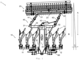
- FIG. 1 shows a top view of a soil cultivation device 1 with a soil cultivation unit 10, namely a full rotary parallel plow, with a soil cultivation device frame 60 on which a first transverse frame 11 and a second transverse frame 12 are rotatably attached via a turning axis.
- the transverse frames 11, 12 can be rotated separately, independently of one another, about their turning axis by essentially 180°. In a first working position, the transverse frames 11, 12 thus extend essentially transversely to a working direction A of the floor treatment unit 10 and essentially parallel to the floor to be worked, which extends parallel to the plane of the drawing 1 below the tillage implement 1 is located.
- the transverse frames 11, 12 are in a position rotated by 180° with respect to the first working position.
- the transverse frames 11, 12 carry plow bodies as examples of tillage tools 13.
- the plow bodies include both left-turning and right-turning plow bodies, and one left-turning one each and a right-turning plow body form a plow body pair.
- In the first working position of the soil treatment unit 10 only the left-hand plow bodies interact with the soil, in the second working position only the right-hand plow bodies.
- the working position of the soil treatment unit 10 shown is the left-hand working position, ie a soil beam which is picked up by a plow body is laid further to the left of its original position on the soil, as seen in the working direction A.
- the furthest left plow body lays down its ground bar in a left-hand side area B, even outside the working width of the soil treatment unit 10 .
- This interaction of the plow bodies with the soil, which causes the soil beam to move to the left, causes the soil tillage unit 10 to pull to the right in working direction A.
- the soil tillage implement 1 also has a hitch 30 which is connected to the soil tillage implement frame 60 .
- the hitch 30 runs in a central area from the soil cultivation device frame 60 to the rear.
- the hitch 30 towers over and spans the plow body like a bridge. in the in 1
- the hitch 30 appears essentially T-shaped, with a first crossbeam 33 and a second crossbeam 34, or a single continuous crossbeam, on either side of a longitudinal beam 35 of the hitch 30 behind the plow bodies, transverse to the working direction A, i.e. parallel to the Tillage implement frame 60, each extend to a free end.
- At the free end of the first transom 33 is a tillage unit attachment 31 and at the free end of the second transom 34 is a tillage unit attachment 32.
- the soil conditioning unit 20 is designed as a packer roller. This is located behind the plow bodies. When working the soil, the packer roller rotates about an axis of rotation R. Soil preparation unit attachments 21 and 22 are located on a transverse frame 23 of the packer roller, which runs essentially parallel to the axis of rotation R.
- the packer roller is set at a left-hand setting angle ⁇ 1 relative to the working direction A by means of a setting mechanism 40 .
- the axis of rotation R is therefore not perpendicular to the working direction A.
- the adjusting mechanism 40 has a first steering rod 41 and a second steering rod 42, both of which have the same length.
- One end of the linkage 41 is pivotally connected to the first transom 33 by means of the tillage unit attachment 31 , while the other end of the linkage 41 is pivotally connected by means of the preparation unit attachment 21 to the packer roller.
- the packer roller i.e. the soil cultivation unit 20
- the full rotary parallel plow i.e. the soil cultivation unit 10
- the two steering rods 41, 42 in such a way that it is located behind the plow bodies, i.e. the soil cultivation tools 13.
- the configuration of the adjusting mechanism 40 by means of two steering rods 41, 42 makes it possible to adjust the packer roller and at the same time laterally offset in such a way that one side of the packer roller protrudes beyond the plow body to the left in the left side area B, ie protrudes laterally from the working width of the soil tillage tools 13 .
- the packer roller is therefore not arranged in alignment with the soil cultivation unit 10 . This ensures that a soil bar processed by the extreme left plow body and turned to the left, which is essentially placed in the left side area B to the left of the plow body, is caught by the packer roller for post-processing, eg reconsolidation.
- the tillage unit attachments 31, 32 are provided on the hitch 30 which extends rearwardly over the tillage implements 13.
- the two tillage unit attachments 31, 32 are arranged on two separate hitch devices which extend substantially vertically upwards at the two ends of the tillage implement frame 60.
- the connecting rods 41, 42 then span the soil tillage tools 13.
- the turning axes of the two transverse frames 11, 12 extend so far to the rear that they have a free end behind the soil tillage tools 13 .
- the soil treatment unit attachments 31, 32 can then be provided on these free ends, ie the turning axles also take on the function of a towing device.
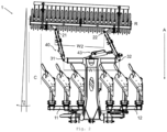
- FIG. 2 shows a top view of the soil cultivation device 1 described above in a right-hand working position.
- the transverse frames 11 and 12 are now rotated 180° about their turning axis running parallel to the working direction A, with the result that the right-turning working position of the Plow body is used to till the soil.
- the packer roller with the setting mechanism 40 is set at a right setting angle ⁇ 2 relative to the working direction A. Although this has the same amount as the angle of attack ⁇ 1, the direction of deflection now points to the right.
- the axis of rotation R is thus rotated clockwise by the angle ⁇ 2 with respect to a perpendicular to the working direction A.
- the packer roller is offset to the right-hand side of the tillage unit 10, ie the full rotary parallel plough. This ensures that the packer roller in the right-hand working position of the full rotary parallel plow also travels over a right-hand side area C to the right of the plow body and reworked, e.g. reconsolidated, into which a plow body arranged furthest to the right deposits the soil beam it has worked on and turned to the right.
- the packer roller exerts a lateral pulling force on the soil cultivation unit 10 during operation, as illustrated below using the example of the left-hand working position. An analogous consideration applies to the right-hand working position.
- the left-turning working position means that the tillage tools 13 of the tillage unit 10 turn the soil to the left, which causes the tillage unit 10 to pull to the right.
- the soil finishing unit 20, here the packer roller is set to the left at an angle of attack ⁇ 1 relative to the working direction A, which, due to its interaction with the soil, leads to a lateral traction force directed to the left.
- the rotary parallel plow pulls the tillage implement 1 to the right, while the packer roller pulls the tillage implement 1 to the left.
- the size of the lateral traction of the soil preparation unit 20 can be to a certain extent via the size of the angle of attack ⁇ 1 and via the force with which the soil post-processing unit 20 interacts with the soil. With a suitable choice of the angle of attack, a straight run of the soil cultivation implement 1 can be ensured by means of the packer roller.
- the steering rods 41 and 42 are in the soil tillage implement 1, which is 1 and 2 shown, arranged so that they diverge in the direction of travel A. This means that a distance between both handlebars 41 and 42 increases toward the front. In other words, as in 2 is shown, a first attachment distance W1 between the tillage unit attachments 31 and 32, which corresponds to the distance between the front ends of the handlebars 41 and 42, is greater than a second attachment distance W2 between the ground preparation unit attachments 21 and 22, which corresponds to the distance between the rear ends of the handlebars 41 and 42 corresponds.
- the lengths of the steering rods 41 and 42 are the same in this embodiment, so that the first and second soil processing unit attachments 31, 32 and the first and second soil conditioning unit attachments 21 and 22, in particular in a neutral position of the packer roller in which the axis of rotation R is perpendicular to the working direction A, set up a steering trapeze.
- This configuration of the steering rods 41 and 42 ensures that the adjustment mechanism 40 simultaneously offsets the packer roller to one side of the soil cultivation device 1 and adjusts it at an angle of attack in the same direction.
- the adjustment mechanism 40 has a hydraulic cylinder 43 in order to enable the packer roller to be switched over. This is at a first end via a joint with the second steering rod 42 and at a second, other end via a another joint with one or both of the crossbars 33, 34 connected.
- the hydraulic cylinder 43 in a first, extended position, which results in a displacement and an adjustment of the packer roller to the left.
- This first position corresponds to a first end stop with an angle of attack ⁇ 1.
- the lateral pulling force exerted by the packer roller is transmitted to the hitch 30 by the adjusting mechanism 40 .
- the hydraulic cylinder 43 in a second, retracted position, which results in a shifting and an adjustment of the packer roller to the right.
- This second position corresponds to a second end stop with an angle of attack ⁇ 2.
- the lateral pulling force exerted by the packer roller is also transmitted to the hitch 30 by the adjusting mechanism 40 in the second position.
- first and second end stops do not necessarily have to correspond to the extended or retracted position of the hydraulic cylinder 43, but intermediate positions can optionally also be defined as the working position.
- the setting angles ⁇ 1, ⁇ 2 can be adjusted by adjusting the first and second end stop.
- the angle of attack can also be adjusted by changing the geometry of the steering trapezium spanned by the first and second soil preparation unit attachments 31 and 32 and by the first and second soil preparation unit attachments 21 and 22, for example by changing the lengths of the first and second connecting rods 41, 42.
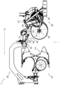
- FIG. 3 shows the soil cultivation device 1 described above in a further right-hand working position.
- the second attachment distance W2 between the first floor finish unit attachment 21 and the second floor finish unit attachment 22 is larger and thus closer to the first attachment distance W1.
- the steering trapezium spanned by the first and second soil preparation unit attachments 31 and 32 and the first and second soil preparation unit attachments 21 and 22 approaches the configuration 2 a parallelogram.
- the changed geometry of the steering trapeze means that the angle of attack ⁇ 2 is smaller than in the in 2 shown setting, although the packer roller is laterally offset by a larger distance.
- FIG. 4 shows the soil tillage implement 1 1 in a side view.
- the bridge-shaped hitch 30 is clearly visible, to which the packer roller is attached behind the plow bodies.
- the full rotary parallel plow is in the right-hand working position, ie the right-hand tillage tools 13 are arranged for tilling the soil.
- the packer roller is in 4 shifted in the direction of view and employed opposite this, ie the axis of rotation R of the packer roller is not exactly perpendicular to the plane of the drawing.
- the packer roller is attached to the hitch 30 of the soil cultivation device 1 by means of the adjustment mechanism 40 .
- the left-hand steering rod 42 can be seen in the illustration shown, which is pivotably attached to the soil treatment unit attachment 32.
- the handlebar 42 is designed in several parts and comprises an upper handlebar leg 51, a lower handlebar leg 52, a front handlebar leg 53 and a rear handlebar leg 54.
- the front handlebar leg 53 and the rear handlebar leg 54 can be rotated at one of its two ends with the upper handlebar leg 51 or the lower handlebar leg 52 connected.
- the handlebar legs 51, 52, 53, 54 thus form the legs of a parallelogram height guide 50.
- the parallelogram height guide 50 By means of the parallelogram height guide 50, it is possible to adjust the height of the packer roller relative to the height of the plow body.
- the packer roller applies part of the weight of the soil cultivation device 1 to the soil.
- the distribution of this weight to the soil cultivation unit 20, the soil cultivation tools 13 and a tractor connected to the soil cultivation device 1 (not shown) can be influenced and adjusted with this parallelogram height guide 50.
- rotating disc coulters 45 are attached to the packer roller to reinforce the interaction of the soil conditioning unit 20 with the soil, in particular the lateral traction force that can be applied.
- the disc coulters 45 each rotate about their own axes of rotation S, which are arranged parallel to the axis of rotation R of the packer roller. If necessary, they can Axis of rotation S but also compared to the axis of rotation R further employed.
- a plant 46 of the packer roller is also shown, which slides through the ground during processing.
- the system 46 is set at the same angle to the working direction A as the packer roller and thereby increases the lateral pulling force exerted by the packer roller on the soil tillage implement 1 .
- the system 46 is connected to the packer roller via a folding joint 47 in such a way that the system 46 can be lifted out of the ground if necessary.
- an interaction with the ground for example a lateral traction force, can be selectively increased via the foldable system 46 if required.
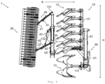
- FIG 5 shows a further embodiment of a soil cultivation device 1 in a transport position.
- Equal and corresponding elements of tillage implement 1 figure 5 and that of one of the other figures are identified by the same reference symbols, if necessary.
- the soil treatment unit 10, also in this embodiment a fully rotating parallel plow, has a first transverse frame 111, which is supported by a first boom 61. On the first transverse frame 111 plow bodies are mounted in a row as soil tillage tools 13 .
- the first boom 61 is foldably connected to a soil cultivation device frame 60 via a first lifting axis U1. The first boom 61 can thus be let down and lifted up.
- the boom 61 is raised such that the first transverse frame 111 extends substantially perpendicular to the ground.
- the tillage unit 10 off figure 5 also has a second transverse frame 112, which is perpendicular to the plane of the drawing figure 5 extends and also carries plow body.
- This second transverse frame 112 is shown in FIG figure 5 shown embodiment in contrast to the first transverse frame 111 cannot be raised upwards into a separate transport position.
- the first transverse frame 111 is arranged on the right-hand side of the tillage implement 1, viewed in the working direction A. It is preferred that a corresponding first transverse frame (not shown) is also arranged on the left-hand side of the soil cultivation device 1 .
- a soil finishing unit 20 also in this embodiment a packer roller, with a second boom 62 is attached to a hitch 30 .
- the second boom 62 is rotatably attached at one end to the hitch 30 about a second lifting axis U2 and carries a crossbeam 133 rotatably mounted at its other end.
- the packer roller is attached to the crossbeam 133 in the manner described in more detail below.
- the crossbar 133 can be moved from a working position of the soil cultivation implement 1, not shown here, in which it is essentially parallel to the ground, ie in figure 5 perpendicular to the plane of the drawing, extends into the in figure 5 fold transport position shown, in which it extends substantially perpendicular to the ground.
- Another foldable second boom (not shown) mounted on the left side of hitch 30 supports another packer roller (not shown) in an analogous manner.
- the transom 133 has a first tillage unit attachment 131 at one free end and a second tillage unit attachment 132 at its other free end. Pivotally attached to the tillage unit attachment 131 is one end of a first link 41 and to the tillage unit attachment 132 is one end of a second link 42 pivotally attached. the others Ends of these linkages 41 and 42 are pivotally attached to the soil preparation unit attachments 21, 22, respectively, so that the packer roller is supported via the linkages 41, 42.
- the orientation of the first and second steering rods 41, 42 is determined in FIG figure 5 shown transport position a transport height H of the soil treatment unit 20 and thus to a large extent also of the soil treatment device 1, which can be set smaller than a permissible road transport height by the adjustment mechanism 40, insofar as this is possible due to the dimensions of the soil treatment unit 10.
- the soil finishing unit 20 is lowered as far as possible with the aid of the adjusting mechanism 40 .
- the hydraulic cylinder 43 of the adjustment mechanism 40 is brought into a fully extended position.
- the other packer roller (not shown), which is carried by the foldable second arm (not shown) on the left side of the tillage implement 1 and in which the adjustment mechanism is designed analogously, i.e. in which the hydraulic cylinder is also attached to the left steering rod 42 , which becomes the upper link rod in the transport position, the hydraulic cylinder is fully retracted in the transport position in order to lower the packer roller as far as possible.
- a deviation of the trapezoidal shape from a parallelogram leads to an inclination angle of the packer roller relative to the vertical.
- this angle of inclination can be set to zero by means of an adjustment of the spacing of the tillage unit attachments 21,22.
- the soil preparation unit attachments 131, 132 and the soil preparation unit attachments 21, 22 then span a parallelogram, which in figure 5 however, is not shown.
Landscapes
- Life Sciences & Earth Sciences (AREA)
- Engineering & Computer Science (AREA)
- Mechanical Engineering (AREA)
- Soil Sciences (AREA)
- Environmental Sciences (AREA)
- Soil Working Implements (AREA)
Applications Claiming Priority (1)
| Application Number | Priority Date | Filing Date | Title |
|---|---|---|---|
| DE102021214803.4A DE102021214803A1 (de) | 2021-12-21 | 2021-12-21 | Bodenbearbeitungsgerät |
Publications (3)
| Publication Number | Publication Date |
|---|---|
| EP4201166A1 true EP4201166A1 (fr) | 2023-06-28 |
| EP4201166B1 EP4201166B1 (fr) | 2025-05-07 |
| EP4201166C0 EP4201166C0 (fr) | 2025-05-07 |
Family
ID=84541505
Family Applications (1)
| Application Number | Title | Priority Date | Filing Date |
|---|---|---|---|
| EP22214628.4A Active EP4201166B1 (fr) | 2021-12-21 | 2022-12-19 | Outil de travail du sol |
Country Status (2)
| Country | Link |
|---|---|
| EP (1) | EP4201166B1 (fr) |
| DE (1) | DE102021214803A1 (fr) |
Citations (5)
| Publication number | Priority date | Publication date | Assignee | Title |
|---|---|---|---|---|
| DE2824808A1 (de) * | 1977-09-12 | 1979-03-15 | Ferd Heger & Sohn Landw Maschi | Nivellier- und kruemlerwalzenanordnung |
| DE2752764A1 (de) * | 1977-11-25 | 1979-05-31 | Bayerische Pflugfabrik Gmbh | Geraetekombination zur bodenbearbeitung |
| DE7804395U1 (de) | 1978-02-15 | 1981-02-19 | Rabewerk Heinrich Clausing, 4515 Bad Essen | Bodenbearbeitungsgeraet |
| DE3412512A1 (de) * | 1983-04-06 | 1984-10-11 | National Research Development Corp., London | Bodenbearbeitungsvorrichtung |
| DE10147595A1 (de) | 2001-09-26 | 2003-04-10 | Amazonen Werke Dreyer H | Bodenbearbeitungskombination |
Family Cites Families (1)
| Publication number | Priority date | Publication date | Assignee | Title |
|---|---|---|---|---|
| DE19832620A1 (de) | 1998-07-21 | 2000-01-27 | Dietmar Groh | Vorrichtung zur mehrschichtigen Bodenbearbeitung |
-
2021
- 2021-12-21 DE DE102021214803.4A patent/DE102021214803A1/de active Pending
-
2022
- 2022-12-19 EP EP22214628.4A patent/EP4201166B1/fr active Active
Patent Citations (6)
| Publication number | Priority date | Publication date | Assignee | Title |
|---|---|---|---|---|
| DE2824808A1 (de) * | 1977-09-12 | 1979-03-15 | Ferd Heger & Sohn Landw Maschi | Nivellier- und kruemlerwalzenanordnung |
| DE2752764A1 (de) * | 1977-11-25 | 1979-05-31 | Bayerische Pflugfabrik Gmbh | Geraetekombination zur bodenbearbeitung |
| DE7804395U1 (de) | 1978-02-15 | 1981-02-19 | Rabewerk Heinrich Clausing, 4515 Bad Essen | Bodenbearbeitungsgeraet |
| DE3412512A1 (de) * | 1983-04-06 | 1984-10-11 | National Research Development Corp., London | Bodenbearbeitungsvorrichtung |
| DE10147595A1 (de) | 2001-09-26 | 2003-04-10 | Amazonen Werke Dreyer H | Bodenbearbeitungskombination |
| DE10147595B4 (de) * | 2001-09-26 | 2018-05-09 | Amazonen-Werke H. Dreyer Gmbh & Co. Kg | Bodenbearbeitungskombination |
Also Published As
| Publication number | Publication date |
|---|---|
| EP4201166B1 (fr) | 2025-05-07 |
| DE102021214803A1 (de) | 2023-06-22 |
| EP4201166C0 (fr) | 2025-05-07 |
Similar Documents
| Publication | Publication Date | Title |
|---|---|---|
| DE2838829C2 (de) | Mehrschariger Aufsattelpflug | |
| DE102014109605B4 (de) | Schwenkstützrad zum Anbau an einen Pflugrahmen | |
| EP1935224B1 (fr) | Engin agricole tracté à largeur de travail plus grande | |
| DE102017116633A1 (de) | Landwirtschaftliche Bodenbearbeitungsmaschine | |
| WO2013091608A2 (fr) | Appareil pour le travail du sol intégré pour charrue brabant | |
| EP3434089B1 (fr) | Machine agricole de traitement du sol | |
| EP3800976B1 (fr) | Appareil agricole de travail du sol et procédé permettant de faire fonctionner ledit appareil | |
| DE3529517C2 (de) | Pflug | |
| DE3530107C2 (de) | Pflug | |
| EP2220922B1 (fr) | Charrue | |
| EP3381253A1 (fr) | Engin agricole doté d'éléments de guidage en profondeur | |
| DE4306145A1 (de) | Gerätekombination zum Pflügen landwirtschaftlicher Nutzflächen und zur Bodennachbearbeitung und/oder Bodenbestellung | |
| EP4201166B1 (fr) | Outil de travail du sol | |
| DE2639608C2 (fr) | ||
| EP1625781B1 (fr) | Charrue portée réversible | |
| DE69607420T2 (de) | Mehrteildrehpflug | |
| EP2371194B1 (fr) | Dispositif de répartition de semences et/ou d'engrais | |
| DE69910683T2 (de) | Sähmaschine | |
| DE69910904T2 (de) | Sähmaschine | |
| DE2450386A1 (de) | Pflugsystem mit mehreren einzelpfluegen kontinuierlich einstellbarem abstand | |
| DE69902668T2 (de) | Mechanismus zur seitlichen justierung eines aufsattelpflugs | |
| DE4031503C2 (de) | Aufsatteldrehpflug | |
| DE3306650C2 (fr) | ||
| DE19637536C2 (de) | Integrierte Kombination aus einem Pflug und einer Bodenaufbereitungsvorrichtung | |
| DE102017116635A1 (de) | Landwirtschaftliche Bodenbearbeitungsmaschine |
Legal Events
| Date | Code | Title | Description |
|---|---|---|---|
| PUAI | Public reference made under article 153(3) epc to a published international application that has entered the european phase |
Free format text: ORIGINAL CODE: 0009012 |
|
| STAA | Information on the status of an ep patent application or granted ep patent |
Free format text: STATUS: THE APPLICATION HAS BEEN PUBLISHED |
|
| AK | Designated contracting states |
Kind code of ref document: A1 Designated state(s): AL AT BE BG CH CY CZ DE DK EE ES FI FR GB GR HR HU IE IS IT LI LT LU LV MC ME MK MT NL NO PL PT RO RS SE SI SK SM TR |
|
| STAA | Information on the status of an ep patent application or granted ep patent |
Free format text: STATUS: REQUEST FOR EXAMINATION WAS MADE |
|
| 17P | Request for examination filed |
Effective date: 20240102 |
|
| RBV | Designated contracting states (corrected) |
Designated state(s): AL AT BE BG CH CY CZ DE DK EE ES FI FR GB GR HR HU IE IS IT LI LT LU LV MC ME MK MT NL NO PL PT RO RS SE SI SK SM TR |
|
| GRAP | Despatch of communication of intention to grant a patent |
Free format text: ORIGINAL CODE: EPIDOSNIGR1 |
|
| STAA | Information on the status of an ep patent application or granted ep patent |
Free format text: STATUS: GRANT OF PATENT IS INTENDED |
|
| RIC1 | Information provided on ipc code assigned before grant |
Ipc: A01B 49/02 20060101ALI20240510BHEP Ipc: A01B 17/00 20060101AFI20240510BHEP |
|
| INTG | Intention to grant announced |
Effective date: 20240610 |
|
| RAP3 | Party data changed (applicant data changed or rights of an application transferred) |
Owner name: LEMKEN GMBH & CO. KG |
|
| GRAJ | Information related to disapproval of communication of intention to grant by the applicant or resumption of examination proceedings by the epo deleted |
Free format text: ORIGINAL CODE: EPIDOSDIGR1 |
|
| STAA | Information on the status of an ep patent application or granted ep patent |
Free format text: STATUS: REQUEST FOR EXAMINATION WAS MADE |
|
| INTC | Intention to grant announced (deleted) | ||
| GRAP | Despatch of communication of intention to grant a patent |
Free format text: ORIGINAL CODE: EPIDOSNIGR1 |
|
| STAA | Information on the status of an ep patent application or granted ep patent |
Free format text: STATUS: GRANT OF PATENT IS INTENDED |
|
| INTG | Intention to grant announced |
Effective date: 20241203 |
|
| GRAS | Grant fee paid |
Free format text: ORIGINAL CODE: EPIDOSNIGR3 |
|
| GRAA | (expected) grant |
Free format text: ORIGINAL CODE: 0009210 |
|
| STAA | Information on the status of an ep patent application or granted ep patent |
Free format text: STATUS: THE PATENT HAS BEEN GRANTED |
|
| AK | Designated contracting states |
Kind code of ref document: B1 Designated state(s): AL AT BE BG CH CY CZ DE DK EE ES FI FR GB GR HR HU IE IS IT LI LT LU LV MC ME MK MT NL NO PL PT RO RS SE SI SK SM TR |
|
| REG | Reference to a national code |
Ref country code: GB Ref legal event code: FG4D Free format text: NOT ENGLISH |
|
| REG | Reference to a national code |
Ref country code: CH Ref legal event code: EP |
|
| REG | Reference to a national code |
Ref country code: DE Ref legal event code: R096 Ref document number: 502022003857 Country of ref document: DE |
|
| REG | Reference to a national code |
Ref country code: IE Ref legal event code: FG4D Free format text: LANGUAGE OF EP DOCUMENT: GERMAN |
|
| U01 | Request for unitary effect filed |
Effective date: 20250516 |
|
| U07 | Unitary effect registered |
Designated state(s): AT BE BG DE DK EE FI FR IT LT LU LV MT NL PT RO SE SI Effective date: 20250522 |
|
| PG25 | Lapsed in a contracting state [announced via postgrant information from national office to epo] |
Ref country code: ES Free format text: LAPSE BECAUSE OF FAILURE TO SUBMIT A TRANSLATION OF THE DESCRIPTION OR TO PAY THE FEE WITHIN THE PRESCRIBED TIME-LIMIT Effective date: 20250507 |
|
| PG25 | Lapsed in a contracting state [announced via postgrant information from national office to epo] |
Ref country code: GR Free format text: LAPSE BECAUSE OF FAILURE TO SUBMIT A TRANSLATION OF THE DESCRIPTION OR TO PAY THE FEE WITHIN THE PRESCRIBED TIME-LIMIT Effective date: 20250808 Ref country code: NO Free format text: LAPSE BECAUSE OF FAILURE TO SUBMIT A TRANSLATION OF THE DESCRIPTION OR TO PAY THE FEE WITHIN THE PRESCRIBED TIME-LIMIT Effective date: 20250807 |
|
| PG25 | Lapsed in a contracting state [announced via postgrant information from national office to epo] |
Ref country code: PL Free format text: LAPSE BECAUSE OF FAILURE TO SUBMIT A TRANSLATION OF THE DESCRIPTION OR TO PAY THE FEE WITHIN THE PRESCRIBED TIME-LIMIT Effective date: 20250507 |
|
| PG25 | Lapsed in a contracting state [announced via postgrant information from national office to epo] |
Ref country code: HR Free format text: LAPSE BECAUSE OF FAILURE TO SUBMIT A TRANSLATION OF THE DESCRIPTION OR TO PAY THE FEE WITHIN THE PRESCRIBED TIME-LIMIT Effective date: 20250507 |
|
| PG25 | Lapsed in a contracting state [announced via postgrant information from national office to epo] |
Ref country code: RS Free format text: LAPSE BECAUSE OF FAILURE TO SUBMIT A TRANSLATION OF THE DESCRIPTION OR TO PAY THE FEE WITHIN THE PRESCRIBED TIME-LIMIT Effective date: 20250807 |
|
| PG25 | Lapsed in a contracting state [announced via postgrant information from national office to epo] |
Ref country code: IS Free format text: LAPSE BECAUSE OF FAILURE TO SUBMIT A TRANSLATION OF THE DESCRIPTION OR TO PAY THE FEE WITHIN THE PRESCRIBED TIME-LIMIT Effective date: 20250907 |
|
| PG25 | Lapsed in a contracting state [announced via postgrant information from national office to epo] |
Ref country code: SM Free format text: LAPSE BECAUSE OF FAILURE TO SUBMIT A TRANSLATION OF THE DESCRIPTION OR TO PAY THE FEE WITHIN THE PRESCRIBED TIME-LIMIT Effective date: 20250507 |
|
| PG25 | Lapsed in a contracting state [announced via postgrant information from national office to epo] |
Ref country code: CZ Free format text: LAPSE BECAUSE OF FAILURE TO SUBMIT A TRANSLATION OF THE DESCRIPTION OR TO PAY THE FEE WITHIN THE PRESCRIBED TIME-LIMIT Effective date: 20250507 |
|
| PG25 | Lapsed in a contracting state [announced via postgrant information from national office to epo] |
Ref country code: SK Free format text: LAPSE BECAUSE OF FAILURE TO SUBMIT A TRANSLATION OF THE DESCRIPTION OR TO PAY THE FEE WITHIN THE PRESCRIBED TIME-LIMIT Effective date: 20250507 |
|
| U20 | Renewal fee for the european patent with unitary effect paid |
Year of fee payment: 4 Effective date: 20260102 |
|
| PLBE | No opposition filed within time limit |
Free format text: ORIGINAL CODE: 0009261 |
|
| STAA | Information on the status of an ep patent application or granted ep patent |
Free format text: STATUS: NO OPPOSITION FILED WITHIN TIME LIMIT |
|
| REG | Reference to a national code |
Ref country code: CH Ref legal event code: L10 Free format text: ST27 STATUS EVENT CODE: U-0-0-L10-L00 (AS PROVIDED BY THE NATIONAL OFFICE) Effective date: 20260318 |
|
| 26N | No opposition filed |
Effective date: 20260210 |