EP4201501B1 - Installation de trempe par lots pourvue d'un système de nettoyage destiné au nettoyage par lot par zones de l'installation de trempe par lots et procédé de nettoyage par lot au moyen d'un système de nettoyage - Google Patents
Installation de trempe par lots pourvue d'un système de nettoyage destiné au nettoyage par lot par zones de l'installation de trempe par lots et procédé de nettoyage par lot au moyen d'un système de nettoyage Download PDFInfo
- Publication number
- EP4201501B1 EP4201501B1 EP22212723.5A EP22212723A EP4201501B1 EP 4201501 B1 EP4201501 B1 EP 4201501B1 EP 22212723 A EP22212723 A EP 22212723A EP 4201501 B1 EP4201501 B1 EP 4201501B1
- Authority
- EP
- European Patent Office
- Prior art keywords
- batch
- collecting container
- foam
- installation
- mixture
- Prior art date
- Legal status (The legal status is an assumption and is not a legal conclusion. Google has not performed a legal analysis and makes no representation as to the accuracy of the status listed.)
- Active
Links
Images

Classifications
-
- B—PERFORMING OPERATIONS; TRANSPORTING
- B01—PHYSICAL OR CHEMICAL PROCESSES OR APPARATUS IN GENERAL
- B01D—SEPARATION
- B01D21/00—Separation of suspended solid particles from liquids by sedimentation
- B01D21/02—Settling tanks with single outlets for the separated liquid
- B01D21/04—Settling tanks with single outlets for the separated liquid with moving scrapers
-
- B—PERFORMING OPERATIONS; TRANSPORTING
- B01—PHYSICAL OR CHEMICAL PROCESSES OR APPARATUS IN GENERAL
- B01D—SEPARATION
- B01D21/00—Separation of suspended solid particles from liquids by sedimentation
- B01D21/24—Feed or discharge mechanisms for settling tanks
- B01D21/2433—Discharge mechanisms for floating particles
- B01D21/2438—Discharge mechanisms for floating particles provided with scrapers on the liquid surface for removing floating particles
-
- B—PERFORMING OPERATIONS; TRANSPORTING
- B01—PHYSICAL OR CHEMICAL PROCESSES OR APPARATUS IN GENERAL
- B01D—SEPARATION
- B01D21/00—Separation of suspended solid particles from liquids by sedimentation
- B01D21/24—Feed or discharge mechanisms for settling tanks
- B01D21/245—Discharge mechanisms for the sediments
- B01D21/2461—Positive-displacement pumps; Screw feeders; Trough conveyors
-
- B—PERFORMING OPERATIONS; TRANSPORTING
- B01—PHYSICAL OR CHEMICAL PROCESSES OR APPARATUS IN GENERAL
- B01D—SEPARATION
- B01D21/00—Separation of suspended solid particles from liquids by sedimentation
- B01D21/26—Separation of sediment aided by centrifugal force or centripetal force
Definitions
- the invention relates to a batch-off plant with a cleaning system for section-by-section cleaning of the batch-off plant according to the combination of features of patent claim 1. Furthermore, the invention relates to a method for section-by-section cleaning in a batch-off plant with a cleaning system according to the combination of features of patent claim 10.
- Batch-off systems are systems that are installed downstream of a rolling mill, for example. With the help of a batch-off system, the rubber sheets produced using a calendering process are firstly cooled and then folded into easily manageable volumes.
- the anti-adhesive agent is applied by coating the rubber sheet with the anti-adhesive agent using a coating device.
- the coating device essentially comprises an immersion tank through which the rubber sheet can be passed.
- a solution containing an anti-adhesive agent is located in the immersion tank.
- the invention is based on the idea that a cleaning system according to the invention for at least partially cleaning a batch-off system has at least one collecting container for a mixture to be collected.
- the mixture to be collected contains at least anti-adhesion agent residues.
- the at least one collecting container has at least one foam skimming device, wherein the foam skimming device is designed to separate foam components of the mixture from liquid components of the mixture and transport the foam components to a foam collection container.
- a foam skimming device By implementing a foam skimming device, it is possible to perform section-by-section cleaning, i.e., at least one cleaning in a selected section of the batch-off system.
- a foam skimming device can be used to perform at least partial cleaning during operation of the batch-off system, allowing further cleaning and separation steps without shutting down the batch-off system.
- the mixture to be collected preferably contains water and/or material sections or material particles of the rubber component to be processed in the batch-off system, in particular the rubber band.
- the anti-adhesion agent itself is preferably a mixture of various chemicals. These can include inert minerals combined with calcium stearate, detergents, antifoams, and rust inhibitors.
- the anti-adhesion agent residues may therefore contain components of the aforementioned powder compositions.
- the foam skimming device comprises at least one wall or plate inclined in relation to the horizontal of the collecting container and a movable, in particular horizontally movable, spatula.
- a horizontal axis of the collecting container is understood to mean, in particular, an axis that runs parallel to a liquid surface formed in the collecting container.
- the inclined wall or the inclined plate is thus inclined to the horizontal and to the liquid surface formed in the collecting container.
- An inclined wall is understood to mean, in particular, a wall or housing section of the collecting container.
- a section of the collecting container itself is preferably designed to be inclined.
- An inclined plate is preferably a separately formed component connected to the collecting container.
- the spatula which is movable in particular horizontally, is, for example, a plastic element that is movable above the inclined surface or inclined plate. Due to the movement of the spatula, which is horizontal in particular, a foam component of the mixture formed on the liquid surface can be pushed along the inclined surface or inclined plate towards an edge section of the collecting container, so that the foam component of the mixture is separated from the liquid components of the mixture and The foam can be transported to a foam collection container. This allows the foam to be skimmed off at the collection container.
- the spatula can generally be described or designed as an elongated component that enables a sweeping movement over a liquid surface.
- a first collection container is preferably located below a coating device of the batch-off system.
- the coating device can be a dipping tank or immersion tank.
- the mixture in the immersion tank or dipping tank, which contains anti-adhesion agent residues, can thus be drained vertically downward into the first collection container.
- a preferably at least second collecting container can be arranged below a drip zone of the batch-off system.
- a drip zone is the drying area of a batch-off system in which the anti-adhesive agent initially deposited on the rubber sheet can drip off.
- the at least one collecting container in particular the first collecting container, has a collecting section in the bottom section, in particular a conical section, which is designed to collect solids from the mixture.
- the solids of the mixture can be powder components of the anti-adhesion agent.
- the solids can be particles or material sections of the rubber sheet or rubber material to be treated in the batch-off system.
- a depression is preferably formed which can serve as a collecting section for the heavier solids of the mixture.
- the at least one collecting container in particular the first collecting container, can be fluidly connected to a centrifuge, a centrifugal separator, or a screw conveyor.
- the collecting container particularly in the area of the collecting section, may have a solids discharge opening through which the collected solids can be removed from the collecting container and transported to a centrifuge, a centrifugal separator, or a screw conveyor.
- the screw conveyor is formed in the collecting container, in particular in the area of the collecting section, so that the solids collected in the collecting section can be transported out of the collecting container.
- the foam collection container may comprise a filter device, in particular a sieve separator, which is designed to separate residual liquid from the foam component located in the foam collection container.
- the foam collection container can be fluidly connected to a waste collection container, wherein the waste collection container preferably has a filter device, in particular a sieve separator, which is designed to separate residual liquid from the materials located in the waste collection container.
- a filter device in particular a sieve separator
- the separated foam components are transported to a common foam collection container. It is therefore possible that, despite the provision of multiple collection containers, only one foam collection container is provided in the cleaning system.
- a rinsing and/or spraying device in a/the dripping zone of the batch-off system, which is designed to dilute the mixture to be collected in the dripping zone.
- the at least second collecting container which is formed in a/the drip zone, is designed as an elongated collecting container having an inclined wall in one section.
- the inclined wall is formed by the collecting container itself. Since the mixture to be collected has a lower viscosity in the drip zone than, for example, in the area of the coating device, it is advantageous to dilute the mixture to be collected in the drip zone so that appropriate skimming of foam can occur.
- the purification system With the help of the purification system according to the invention, it is possible to purify mixtures that previously had to be disposed of completely as waste products of a batch-off plant using several components included in the purification system. It is possible to reuse the liquid components of the collected mixture thus separated in the batch-off plant.
- a further aspect of the invention relates to a method for section-by-section cleaning in a batch-off system with a cleaning system.
- the method according to the invention provides that a mixture containing anti-adhesion agent residues is collected at least section-by-section in at least one collecting container.
- the foam skimming device designed according to the invention preferably regularly separates foam components of the mixture from liquid components of the mixture, and the foam components are transported to a foam collection container.
- the foam skimming device is activated at regular time intervals, the time interval being 20 min to 240 min, in particular 30 min to 120 min, in particular 45 min to 80 min.
- the cleaning system has several collecting containers, each with its own foam skimming device, it is possible for the respective foam skimming devices to be activated in parallel or at different times.
- the advantage of staggered activation of multiple foam skimmers is that the foam components collected in each case can be cleaned continuously.
- the post-treatment or subsequent cleaning steps associated with the skimmed foam components can be carried out more quickly due to the smaller amounts of foam components collected in each case.
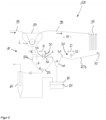
- Fig. 1 shows schematically the basic structure of a cleaning system 10 according to the invention for section-by-section cleaning of a batch-off system 100.
- a rubber sheet 99 is cooled and coated with an anti-adhesive agent so that the rubber sheet 99 can be transported or processed further in a stacked or folded form 98.
- the batch-off system 100 has a coating device 90.
- the coating device 90 is designed as a type of dipping tank through which the rubber belt 99 can be guided.
- An anti-adhesion agent solution L is located in the dipping tank, so that the rubber sheet 99 can be coated with the appropriate anti-adhesion agent.
- the anti-adhesion agent solution is a mixture of water and anti-adhesion agent, with the anti-adhesion agent being present, for example, at a concentration of 2 to 4 wt.%, measured against the total mixture.
- a mixture G containing anti-adhesive residues is collected in a collecting container 20a.
- the mixture G may contain, for example, rubber components or rubber particles.
- the collecting container 20a further comprises a foam skimming device 30.
- the foam skimming device 30 comprises at least one plate 32 inclined relative to the horizontal 21 of the collecting container 20a and a movable spatula 33.
- the spatula 33 can be moved horizontally in the direction of movement D, as indicated by the arrow.
- a foam component S of the mixture G can be separated from liquid components F of the mixture G and transported to a foam collection container 40.
- the first collection container 20a is arranged vertically below the coating device 90.
- the cleaning system 10 has a second collecting container 20b.
- the second collecting container 20b is arranged vertically below the drip zone 95 of the batch-off system 100. In the drip zone 95, drops of the anti-adhesion agent can detach from the coated rubber sheet 99.
- the second collecting container 20b has an inclined wall 31.
- the inclined wall 31 is part of the foam skimming device 30.
- a gap 33 is also formed in connection with the second collecting container 20b.
- the spatula 33 can also be moved in the direction of movement D. When the spatula 33 is moved to the left, a foam component S can thus be transported to the foam collection container 40. A liquid component F of the mixture G, however, initially remains in the second collecting container 20b.
- the inclined plate 32 is formed as a separate component.
- a foam skimming device 30 in order to form a foam skimming device 30, it is necessary to form a separate plate 32 in addition to forming a spatula 33.
- a wall of the collecting container 20b itself is designed as an inclined surface or inclined wall 31.
- the formation of a separate plate is not necessary here.
- a spray device 70 is preferably formed in the region of the second collecting container 20b, so that the anti-adhesion agent drops collected by the second collecting container 20b can be diluted.
- the concentration of the anti-adhesion agent in the foam component S is, for example, approximately 50%.
- the first collecting container 20a has a collecting section 23 in the bottom section 22.
- the collecting section 23 is designed to collect solids M of the mixture G.
- the collecting section 23 is formed, for example, by a conical shape of the bottom section 22.
- the collecting section 23 can also be referred to as a recess of the collecting container 20a in which solids M of the mixture G collect.
- the cleaning system 10 comprises a screw conveyor 50, by means of which the solids M can be transported from the first collecting container 20a.
- the solids M are preferably transported to a waste collection container 80.
- This waste collection container can have a filter device, in particular a sieve separator 85, which is designed to separate residual liquid from the materials located in the waste collection container 80.
- the solid M can, for example, be deposits of the precipitated anti-stick powder and rubber compound particles.
- the precipitated anti-stick powder can be present at a concentration of approximately 75% at this stage.
- waste collection container 80 With the help of the waste collection container 80 and the additionally designed sieve separator 85, it is possible to separate residual liquid from collected waste materials so that this residual liquid can be returned to the batch-off system circuit.
- the foam component S of the foam collection container 40 is also collected in the waste collection container 80 and separated again with the aid of the sieve separator 85.
- the foam collecting container 40 itself to have a filter device, in particular a sieve separator.
- FIG. 2 A further embodiment of the invention is shown.
- This embodiment of the cleaning system 10 differs only in the alternative design of a centrifugal separator 60 instead of a screw conveyor 50.
- the solid M collected in the collection container 20a can be further separated into its liquid and solid components.
- the separated liquid components can be returned to the batch-off system.
- the solids separated by the centrifugal separator 60 can be transported to the waste collection container 80.
- a further separation or purification can be performed using a sieve separator 85.
Landscapes
- Chemical & Material Sciences (AREA)
- Chemical Kinetics & Catalysis (AREA)
- Cleaning By Liquid Or Steam (AREA)
- Cleaning In General (AREA)
Claims (11)
- Installation de coulée par lots (100), comprenant un système de nettoyage (10) pour le nettoyage par endroits de l'installation de coulée par lots (100),
dans laquelle le système de nettoyage (10) présente au moins un récipient collecteur (20a, 20b) pour un mélange (G) à collecter qui contient au moins des résidus d'un produit antiadhésif et au moins un récipient collecteur d'écume (40), dans lequel ledit au moins un récipient collecteur (20a, 20b) présente au moins un dispositif d'écumage (30), dans lequel le dispositif d'écumage (30) est réalisé pour séparer des composants d'écume (S) du mélange (G) des composants liquides (F) du mélange (G) et pour transporter les composants d'écume (S) jusqu'audit au moins un récipient collecteur d'écume (40). - Installation de coulée par lots (100), comprenant un système de nettoyage (10), selon la revendication 1,
caractérisée en ce que
le dispositif d'écumage (30) présente au moins une paroi (31) ou une plaque (32) inclinée par rapport à l'horizontale (21) du récipient collecteur (20a, 20b), et une spatule (33) mobile, en particulier mobile horizontalement. - Installation de coulée par lots (100), comprenant un système de nettoyage (10), selon la revendication 1 ou 2,
caractérisée en ce que
un premier récipient collecteur (20a) est disposé au-dessous d'un dispositif de revêtement (90) de l'installation de coulée par lots (100). - Installation de coulée par lots (100), comprenant un système de nettoyage (10), selon la revendication 3,
caractérisée en ce que
un au moins deuxième récipient collecteur (20b) est disposé au-dessous d'une zone d'égouttage (95) de l'installation de coulée par lots (100). - Installation de coulée par lots (100), comprenant un système de nettoyage (10), selon l'une quelconque des revendications précédentes,
caractérisée en ce que
ledit au moins un récipient collecteur (20a, 20b), en particulier le premier récipient collecteur (20a), présente dans la partie de fond (22) une partie de collecte (23), en particulier de forme conique, qui est réalisé pour collecter des matières solides (M) du mélange (G). - Installation de coulée par lots (100), comprenant un système de nettoyage (10), selon la revendication 5,
caractérisée en ce que
ledit au moins récipient collecteur (20a, 20b), en particulier le premier récipient collecteur (20a), est en liaison fluidique avec une centrifugeuse ou un cyclone (60) ou une vis d'alimentation (50). - Installation de coulée par lots (100), comprenant un système de nettoyage (10), selon l'une quelconque des revendications précédentes,
caractérisée en ce que
le récipient collecteur d'écume (40) présente un dispositif de filtrage, en particulier un séparateur tamiseur, qui est réalisé pour séparer un liquide résiduel du composant d'écume (S) se trouvant dans le récipient collecteur d'écume (40). - Installation de coulée par lots (100), comprenant un système de nettoyage (10), selon l'une quelconque des revendications précédentes,
caractérisée en ce que
le récipient collecteur d'écume (40) est en liaison fluidique avec un récipient collecteur de déchets (80), le récipient collecteur de déchets (80) présentant de préférence un dispositif de filtrage, en particulier un séparateur tamiseur (85), qui est réalisé pour séparer un liquide résiduel des particules de matière se trouvant dans le récipient collecteur de déchets (80). - Installation de coulée par lots (100), comprenant un système de nettoyage (10), selon l'une quelconque des revendications précédentes,
caractérisée par
un dispositif de rinçage et/ou de pulvérisation (70) réalisé dans une zone d'égouttage (95) de l'installation de coulée par lots (100) et qui est réalisé pour diluer le mélange (G) à collecter dans la zone d'égouttage (95). - Procédé de nettoyage par endroits dans une installation de coulée par lots (100) à l'aide d'un système de nettoyage (10) selon l'une quelconque des revendications 1 à 9,
caractérisée en ce que
au moins par endroits, un mélange (G) contenant des résidus d'un produit antiadhésif est collecté dans ledit au moins un récipient collecteur (20a, 20b), dans lequel le dispositif d'écumage (30) permet de séparer, de préférence régulièrement, des composants d'écume (S) du mélange (G) des composants liquides (F) du mélange (G) et de transporter les composants d'écume (S) dans un récipient collecteur d'écume (40). - Procédé selon la revendication 10,
caractérisée en ce quele dispositif d'écumage (30) est activé à intervalles de temps réguliers,l'intervalle de temps étant de 20 min à 240 min, en particulier de 30 min à 120 min, en particulier de 45 min à 80 min.
Applications Claiming Priority (1)
| Application Number | Priority Date | Filing Date | Title |
|---|---|---|---|
| DE102021214793.3A DE102021214793A1 (de) | 2021-12-21 | 2021-12-21 | Reinigungssystem zur abschnittsweisen Reinigung einer Batch-Off Anlage und Verfahren zur abschnittsweisen Reinigung einer Batch-Off Anlage |
Publications (2)
| Publication Number | Publication Date |
|---|---|
| EP4201501A1 EP4201501A1 (fr) | 2023-06-28 |
| EP4201501B1 true EP4201501B1 (fr) | 2025-04-23 |
Family
ID=84488388
Family Applications (1)
| Application Number | Title | Priority Date | Filing Date |
|---|---|---|---|
| EP22212723.5A Active EP4201501B1 (fr) | 2021-12-21 | 2022-12-12 | Installation de trempe par lots pourvue d'un système de nettoyage destiné au nettoyage par lot par zones de l'installation de trempe par lots et procédé de nettoyage par lot au moyen d'un système de nettoyage |
Country Status (2)
| Country | Link |
|---|---|
| EP (1) | EP4201501B1 (fr) |
| DE (1) | DE102021214793A1 (fr) |
Family Cites Families (4)
| Publication number | Priority date | Publication date | Assignee | Title |
|---|---|---|---|---|
| US4005019A (en) * | 1974-09-27 | 1977-01-25 | L.S. Love & Associates Limited | Gravitational separator |
| US20060243677A1 (en) * | 2005-04-27 | 2006-11-02 | Sheahan Donald T | Manure separator |
| KR100992430B1 (ko) * | 2010-03-12 | 2010-11-08 | 코오롱워터텍 주식회사 | 침전 장치 및 이를 포함하는 하ㆍ폐수 처리 장치 |
| WO2012047680A2 (fr) * | 2010-09-27 | 2012-04-12 | World Water Works, Inc. | Séparation de solides flottés |
-
2021
- 2021-12-21 DE DE102021214793.3A patent/DE102021214793A1/de active Pending
-
2022
- 2022-12-12 EP EP22212723.5A patent/EP4201501B1/fr active Active
Also Published As
| Publication number | Publication date |
|---|---|
| EP4201501A1 (fr) | 2023-06-28 |
| DE102021214793A1 (de) | 2023-06-22 |
Similar Documents
| Publication | Publication Date | Title |
|---|---|---|
| DE3629947C2 (de) | Vorrichtung zur kontinuierlichen Abtrennung von Feststoffteilchen aus einer flüssigen Suspension | |
| DE2136290B2 (de) | Verfahren und Vorrichtung zum selektiven Entfernen unterschiedlicher Verunreinigungen aus Gasen | |
| DE3338171A1 (de) | Verfahren und vorrichtung zum trennen von emulsionen bzw. abtrennen von feststoffen aus einer suspension aus feststoffen und einer fluessigkeit mittels druck- bzw. turbo flotation | |
| DE2821097C2 (de) | Vorrichtung zur Dekontamination von radioaktiven Abwässern | |
| EP4201501B1 (fr) | Installation de trempe par lots pourvue d'un système de nettoyage destiné au nettoyage par lot par zones de l'installation de trempe par lots et procédé de nettoyage par lot au moyen d'un système de nettoyage | |
| DE10246540A1 (de) | Reinigungsvorrichtung und Verfahren zur Reinigung von Prozessgas einer Reflowlötanlage | |
| DE3782742T2 (de) | Verfahren und vorrichtung zur regeneration einer dynamischen membran in eine fluessigkeitstrennanlage. | |
| DE4402185A1 (de) | Verfahren und Vorrichtung zum Reinigen von Entfettungsmitteln | |
| DE19709860A1 (de) | Verfahren und Vorrichtung zur Aufbereitung von Kühlschmierstoffen für Werkzeugmaschinen oder dgl. | |
| DE3342689C2 (de) | Filtervorrichtung zum Entfernen von Verunreinigungen aus Flüssigkeiten, insbesondere aus Dispersionsfarben | |
| DE102016108441B4 (de) | Verfahren und Vorrichtung zur Separation eines Stoffgemischs | |
| EP2982426A1 (fr) | Dispositif de criblage, son procédé de fabrication et d'utilisation | |
| DE3242058A1 (de) | Verfahren und vorrichtung zur aufbereitung von feinstkohle | |
| DE4231790A1 (de) | Verfahren und Vorrichtung zum Aufbereiten von Abwässern | |
| WO2000026141A1 (fr) | Installation compacte pour l'epuration mecanique d'eaux usees | |
| DE102020205232B4 (de) | Abfallflüssigkeit-behandlungsvorrichtung | |
| DE4027880C2 (fr) | ||
| CH653395A5 (de) | Verfahren zum betrieb einer gesamtanlage zur herstellung von papier sowie gesamtanlage zur ausfuehrung des verfahrens. | |
| EP4154279B1 (fr) | Procédé de décontamination liquide des objets contaminés radioactivement et retraitement d`eau du procédé | |
| DE4118525C1 (en) | Appts. for cleansing contaminated surfaces using liq. - includes cylindrical housing with high pressure injection nozzle for feed liq., overflow, concentrically arranged sepg. walls and sieve | |
| DE102016113707B4 (de) | Verfahren und Vorrichtung zur Abscheidung von Flüssigkeitsphasen | |
| DE102023111763A1 (de) | Vorrichtung und Verfahren zum Reinigen einer Badflüssigkeit einer Behälterreinigungsvorrichtung | |
| DE19623027C1 (de) | Anlage zum Abscheiden und Trennen von leichteren und schwereren Fremdstoffen aus einem diese Stoffe enthaltenden Behandlungsgut, insbesondere zum Abscheiden von Fremdstoffen aus mit diesen belastetem Sand | |
| DE102014224292B4 (de) | Flüssigkeitsabscheider | |
| EP2422867B1 (fr) | Dispositif de séparation pour systèmes de toilettes sous vide |
Legal Events
| Date | Code | Title | Description |
|---|---|---|---|
| PUAI | Public reference made under article 153(3) epc to a published international application that has entered the european phase |
Free format text: ORIGINAL CODE: 0009012 |
|
| STAA | Information on the status of an ep patent application or granted ep patent |
Free format text: STATUS: THE APPLICATION HAS BEEN PUBLISHED |
|
| AK | Designated contracting states |
Kind code of ref document: A1 Designated state(s): AL AT BE BG CH CY CZ DE DK EE ES FI FR GB GR HR HU IE IS IT LI LT LU LV MC ME MK MT NL NO PL PT RO RS SE SI SK SM TR |
|
| STAA | Information on the status of an ep patent application or granted ep patent |
Free format text: STATUS: REQUEST FOR EXAMINATION WAS MADE |
|
| 17P | Request for examination filed |
Effective date: 20240102 |
|
| RBV | Designated contracting states (corrected) |
Designated state(s): AL AT BE BG CH CY CZ DE DK EE ES FI FR GB GR HR HU IE IS IT LI LT LU LV MC ME MK MT NL NO PL PT RO RS SE SI SK SM TR |
|
| RAP3 | Party data changed (applicant data changed or rights of an application transferred) |
Owner name: CONTINENTAL REIFEN DEUTSCHLAND GMBH |
|
| RIC1 | Information provided on ipc code assigned before grant |
Ipc: B01D 43/00 20060101ALI20241122BHEP Ipc: B01D 21/26 20060101ALI20241122BHEP Ipc: B01D 21/24 20060101ALI20241122BHEP Ipc: B01D 21/04 20060101ALI20241122BHEP Ipc: B01D 21/00 20060101AFI20241122BHEP |
|
| GRAP | Despatch of communication of intention to grant a patent |
Free format text: ORIGINAL CODE: EPIDOSNIGR1 |
|
| STAA | Information on the status of an ep patent application or granted ep patent |
Free format text: STATUS: GRANT OF PATENT IS INTENDED |
|
| INTG | Intention to grant announced |
Effective date: 20250108 |
|
| GRAS | Grant fee paid |
Free format text: ORIGINAL CODE: EPIDOSNIGR3 |
|
| GRAA | (expected) grant |
Free format text: ORIGINAL CODE: 0009210 |
|
| STAA | Information on the status of an ep patent application or granted ep patent |
Free format text: STATUS: THE PATENT HAS BEEN GRANTED |
|
| P01 | Opt-out of the competence of the unified patent court (upc) registered |
Free format text: CASE NUMBER: APP_10976/2025 Effective date: 20250306 |
|
| AK | Designated contracting states |
Kind code of ref document: B1 Designated state(s): AL AT BE BG CH CY CZ DE DK EE ES FI FR GB GR HR HU IE IS IT LI LT LU LV MC ME MK MT NL NO PL PT RO RS SE SI SK SM TR |
|
| REG | Reference to a national code |
Ref country code: GB Ref legal event code: FG4D Free format text: NOT ENGLISH |
|
| REG | Reference to a national code |
Ref country code: CH Ref legal event code: EP |
|
| REG | Reference to a national code |
Ref country code: DE Ref legal event code: R096 Ref document number: 502022003664 Country of ref document: DE |
|
| REG | Reference to a national code |
Ref country code: IE Ref legal event code: FG4D Free format text: LANGUAGE OF EP DOCUMENT: GERMAN |
|
| REG | Reference to a national code |
Ref country code: NL Ref legal event code: MP Effective date: 20250423 |
|
| PG25 | Lapsed in a contracting state [announced via postgrant information from national office to epo] |
Ref country code: NL Free format text: LAPSE BECAUSE OF FAILURE TO SUBMIT A TRANSLATION OF THE DESCRIPTION OR TO PAY THE FEE WITHIN THE PRESCRIBED TIME-LIMIT Effective date: 20250423 |
|
| PG25 | Lapsed in a contracting state [announced via postgrant information from national office to epo] |
Ref country code: FI Free format text: LAPSE BECAUSE OF FAILURE TO SUBMIT A TRANSLATION OF THE DESCRIPTION OR TO PAY THE FEE WITHIN THE PRESCRIBED TIME-LIMIT Effective date: 20250423 Ref country code: PT Free format text: LAPSE BECAUSE OF FAILURE TO SUBMIT A TRANSLATION OF THE DESCRIPTION OR TO PAY THE FEE WITHIN THE PRESCRIBED TIME-LIMIT Effective date: 20250825 Ref country code: ES Free format text: LAPSE BECAUSE OF FAILURE TO SUBMIT A TRANSLATION OF THE DESCRIPTION OR TO PAY THE FEE WITHIN THE PRESCRIBED TIME-LIMIT Effective date: 20250423 |
|
| REG | Reference to a national code |
Ref country code: LT Ref legal event code: MG9D |
|
| PG25 | Lapsed in a contracting state [announced via postgrant information from national office to epo] |
Ref country code: GR Free format text: LAPSE BECAUSE OF FAILURE TO SUBMIT A TRANSLATION OF THE DESCRIPTION OR TO PAY THE FEE WITHIN THE PRESCRIBED TIME-LIMIT Effective date: 20250724 Ref country code: NO Free format text: LAPSE BECAUSE OF FAILURE TO SUBMIT A TRANSLATION OF THE DESCRIPTION OR TO PAY THE FEE WITHIN THE PRESCRIBED TIME-LIMIT Effective date: 20250723 |
|
| PG25 | Lapsed in a contracting state [announced via postgrant information from national office to epo] |
Ref country code: PL Free format text: LAPSE BECAUSE OF FAILURE TO SUBMIT A TRANSLATION OF THE DESCRIPTION OR TO PAY THE FEE WITHIN THE PRESCRIBED TIME-LIMIT Effective date: 20250423 |
|
| PG25 | Lapsed in a contracting state [announced via postgrant information from national office to epo] |
Ref country code: BG Free format text: LAPSE BECAUSE OF FAILURE TO SUBMIT A TRANSLATION OF THE DESCRIPTION OR TO PAY THE FEE WITHIN THE PRESCRIBED TIME-LIMIT Effective date: 20250423 |
|
| PG25 | Lapsed in a contracting state [announced via postgrant information from national office to epo] |
Ref country code: HR Free format text: LAPSE BECAUSE OF FAILURE TO SUBMIT A TRANSLATION OF THE DESCRIPTION OR TO PAY THE FEE WITHIN THE PRESCRIBED TIME-LIMIT Effective date: 20250423 |
|
| PG25 | Lapsed in a contracting state [announced via postgrant information from national office to epo] |
Ref country code: RS Free format text: LAPSE BECAUSE OF FAILURE TO SUBMIT A TRANSLATION OF THE DESCRIPTION OR TO PAY THE FEE WITHIN THE PRESCRIBED TIME-LIMIT Effective date: 20250723 |
|
| PG25 | Lapsed in a contracting state [announced via postgrant information from national office to epo] |
Ref country code: IS Free format text: LAPSE BECAUSE OF FAILURE TO SUBMIT A TRANSLATION OF THE DESCRIPTION OR TO PAY THE FEE WITHIN THE PRESCRIBED TIME-LIMIT Effective date: 20250823 |
|
| PG25 | Lapsed in a contracting state [announced via postgrant information from national office to epo] |
Ref country code: LV Free format text: LAPSE BECAUSE OF FAILURE TO SUBMIT A TRANSLATION OF THE DESCRIPTION OR TO PAY THE FEE WITHIN THE PRESCRIBED TIME-LIMIT Effective date: 20250423 |
|
| PG25 | Lapsed in a contracting state [announced via postgrant information from national office to epo] |
Ref country code: SM Free format text: LAPSE BECAUSE OF FAILURE TO SUBMIT A TRANSLATION OF THE DESCRIPTION OR TO PAY THE FEE WITHIN THE PRESCRIBED TIME-LIMIT Effective date: 20250423 Ref country code: DK Free format text: LAPSE BECAUSE OF FAILURE TO SUBMIT A TRANSLATION OF THE DESCRIPTION OR TO PAY THE FEE WITHIN THE PRESCRIBED TIME-LIMIT Effective date: 20250423 |
|
| PGFP | Annual fee paid to national office [announced via postgrant information from national office to epo] |
Ref country code: AT Payment date: 20260113 Year of fee payment: 4 |
|
| PGFP | Annual fee paid to national office [announced via postgrant information from national office to epo] |
Ref country code: FR Payment date: 20251229 Year of fee payment: 4 |
|
| PG25 | Lapsed in a contracting state [announced via postgrant information from national office to epo] |
Ref country code: CZ Free format text: LAPSE BECAUSE OF FAILURE TO SUBMIT A TRANSLATION OF THE DESCRIPTION OR TO PAY THE FEE WITHIN THE PRESCRIBED TIME-LIMIT Effective date: 20250423 |
|
| PG25 | Lapsed in a contracting state [announced via postgrant information from national office to epo] |
Ref country code: EE Free format text: LAPSE BECAUSE OF FAILURE TO SUBMIT A TRANSLATION OF THE DESCRIPTION OR TO PAY THE FEE WITHIN THE PRESCRIBED TIME-LIMIT Effective date: 20250423 |
|
| REG | Reference to a national code |
Ref country code: DE Ref legal event code: R097 Ref document number: 502022003664 Country of ref document: DE |
|
| PG25 | Lapsed in a contracting state [announced via postgrant information from national office to epo] |
Ref country code: SK Free format text: LAPSE BECAUSE OF FAILURE TO SUBMIT A TRANSLATION OF THE DESCRIPTION OR TO PAY THE FEE WITHIN THE PRESCRIBED TIME-LIMIT Effective date: 20250423 |
|
| PG25 | Lapsed in a contracting state [announced via postgrant information from national office to epo] |
Ref country code: IT Free format text: LAPSE BECAUSE OF FAILURE TO SUBMIT A TRANSLATION OF THE DESCRIPTION OR TO PAY THE FEE WITHIN THE PRESCRIBED TIME-LIMIT Effective date: 20250423 |
|
| PLBE | No opposition filed within time limit |
Free format text: ORIGINAL CODE: 0009261 |
|
| STAA | Information on the status of an ep patent application or granted ep patent |
Free format text: STATUS: NO OPPOSITION FILED WITHIN TIME LIMIT |
|
| REG | Reference to a national code |
Ref country code: CH Ref legal event code: L10 Free format text: ST27 STATUS EVENT CODE: U-0-0-L10-L00 (AS PROVIDED BY THE NATIONAL OFFICE) Effective date: 20260304 |
|
| PG25 | Lapsed in a contracting state [announced via postgrant information from national office to epo] |
Ref country code: RO Free format text: LAPSE BECAUSE OF FAILURE TO SUBMIT A TRANSLATION OF THE DESCRIPTION OR TO PAY THE FEE WITHIN THE PRESCRIBED TIME-LIMIT Effective date: 20250423 |
|
| 26N | No opposition filed |
Effective date: 20260126 |
|
| PGFP | Annual fee paid to national office [announced via postgrant information from national office to epo] |
Ref country code: DE Payment date: 20251231 Year of fee payment: 4 |