EP4201501A1 - Système de nettoyage pour le nettoyage par zones d'une installation de coulée par lots et procédé de nettoyage par zones d'une installation de coulée par lots - Google Patents
Système de nettoyage pour le nettoyage par zones d'une installation de coulée par lots et procédé de nettoyage par zones d'une installation de coulée par lots Download PDFInfo
- Publication number
- EP4201501A1 EP4201501A1 EP22212723.5A EP22212723A EP4201501A1 EP 4201501 A1 EP4201501 A1 EP 4201501A1 EP 22212723 A EP22212723 A EP 22212723A EP 4201501 A1 EP4201501 A1 EP 4201501A1
- Authority
- EP
- European Patent Office
- Prior art keywords
- foam
- batch
- mixture
- cleaning
- collection container
- Prior art date
- Legal status (The legal status is an assumption and is not a legal conclusion. Google has not performed a legal analysis and makes no representation as to the accuracy of the status listed.)
- Granted
Links
Images

Classifications
-
- B—PERFORMING OPERATIONS; TRANSPORTING
- B01—PHYSICAL OR CHEMICAL PROCESSES OR APPARATUS IN GENERAL
- B01D—SEPARATION
- B01D21/00—Separation of suspended solid particles from liquids by sedimentation
- B01D21/02—Settling tanks with single outlets for the separated liquid
- B01D21/04—Settling tanks with single outlets for the separated liquid with moving scrapers
-
- B—PERFORMING OPERATIONS; TRANSPORTING
- B01—PHYSICAL OR CHEMICAL PROCESSES OR APPARATUS IN GENERAL
- B01D—SEPARATION
- B01D21/00—Separation of suspended solid particles from liquids by sedimentation
- B01D21/24—Feed or discharge mechanisms for settling tanks
- B01D21/2433—Discharge mechanisms for floating particles
- B01D21/2438—Discharge mechanisms for floating particles provided with scrapers on the liquid surface for removing floating particles
-
- B—PERFORMING OPERATIONS; TRANSPORTING
- B01—PHYSICAL OR CHEMICAL PROCESSES OR APPARATUS IN GENERAL
- B01D—SEPARATION
- B01D21/00—Separation of suspended solid particles from liquids by sedimentation
- B01D21/24—Feed or discharge mechanisms for settling tanks
- B01D21/245—Discharge mechanisms for the sediments
- B01D21/2461—Positive-displacement pumps; Screw feeders; Trough conveyors
-
- B—PERFORMING OPERATIONS; TRANSPORTING
- B01—PHYSICAL OR CHEMICAL PROCESSES OR APPARATUS IN GENERAL
- B01D—SEPARATION
- B01D21/00—Separation of suspended solid particles from liquids by sedimentation
- B01D21/26—Separation of sediment aided by centrifugal force or centripetal force
Definitions
- the invention relates to a cleaning system for the section-by-section cleaning of a batch-off system according to the combination of features of patent claim 1.
- the invention also relates to a method for the section-by-section cleaning of a batch-off system using a cleaning system according to the invention according to the combination of features of patent claim 10.
- Batch-off systems are systems that are installed, for example, as a result of a rolling mill. With the help of a batch-off system, the rubber webs, which are produced using a calender process, are firstly cooled and secondly placed in easily manageable volumes.
- An anti-adhesion agent is applied by coating the rubber web with the anti-adhesion agent using a coating device.
- the coating device essentially comprises a dip tank through which the rubber sheet can be guided. In the dip tank is a G solution containing an anti-seize agent.
- the solution in the dip tank becomes contaminated during the course of the coating process.
- Several factors are known to contribute to contamination of the release agent solution.
- pieces of rubber or parts of the rubber sheets can get into the anti-adhesive solution due to mechanical stress.
- the anti-seize agent can precipitate and collect, for example, at the bottom of the coater.
- the chemical components that do not end up as a coating on the rubber sheeting go into solution.
- the object of the present invention to use the cleaning system to conserve resources such as water resources and to reuse or clean as high a proportion of the anti-adhesive solution as possible.
- the invention is based on the idea that a cleaning system according to the invention for cleaning a batch-off system at least in sections has at least one collection container for a mixture to be collected.
- the mixture to be collected contains at least anti-adhesive residues.
- the at least one collection container has at least one foam skimming device, the foam skimming device being designed to separate foam components of the mixture from liquid components of the mixture and to transport the foam components to a foam collection container. With the help of the formation of a foam skimming device, it is possible to carry out cleaning in sections, d. H. carry out at least one cleaning in a selected section of the batch-off system.
- the mixture to be collected preferably contains water and/or material sections or material particles of the rubber component to be processed in the batch-off system, in particular the rubber band.
- the anti-adhesion agent itself is preferably a mixture of a wide variety of chemicals. These can be inert minerals in combination with calcium stearate, detergents, antifoams and rust inhibitors.
- the anti-adhesive residues can thus contain components of the powder compositions mentioned.
- the foam skimming device has at least one wall or plate inclined in relation to the horizontal of the collecting container and a movable, in particular horizontally movable, spatula.
- a horizontal line of the collecting container is to be understood in particular as such an axis which runs parallel to a liquid surface formed in the collecting container.
- the inclined wall or the inclined plate is thus inclined to the horizontal and to the liquid surface formed in the collection container.
- An inclined wall is to be understood in particular as a wall or housing section of the collection container.
- a section of the collecting container itself is preferably designed to be inclined.
- An inclined plate is preferably a separately formed component connected to the receptacle.
- the spatula which can be moved, in particular horizontally, is, for example, a plastic element which can be moved above the inclined surface or inclined plate. Due to the, in particular horizontal, movement of the spatula, a foam component of the mixture formed on the liquid surface can be pushed along the inclined surface or inclined plate in the direction of an edge section of the collecting container, so that the foam component of the mixture is separated from liquid components of the mixture and becomes one Foam collection container can be transported. The foam is thus skimmed off at the collection container.
- the spatula may be generically referred to or configured as an elongate member that allows for sweeping motion over a liquid surface.
- a first collection container is preferably arranged below a coating device of the batch-off system.
- the coating device can be a dip tank or a dip tank.
- the mixture located in the immersion container or in the immersion basin, which has residues of anti-adhesive agent, can thus be discharged in a vertical direction downwards into the first collection container.
- a preferably at least second collection container can be arranged below a dripping zone of the batch-off system.
- the drying area of a batch-off system, in which the anti-adhesive agent initially on the rubber web can still drip off, is to be understood as a dripping zone.
- the at least one collecting container in particular the first collecting container, has a collecting section in the bottom section, in particular a conically shaped collecting section, which is designed to collect solids of the mixture.
- the solids of the mixture can be powder components of the anti-adhesion agent.
- the solids can be particles or material sections of the rubber sheet or rubber material to be treated in the batch-off system.
- such a recess is preferably formed in the bottom section, which is preferably formed in the vertical direction opposite to the foam skimming device of the collecting container, which depression can serve as a collecting section for the heavier solids of the mixture.
- the at least one collecting container in particular the first collecting container, can be fluidly connected to a centrifuge or to a centrifugal separator or to a screw conveyor.
- the collection container particularly in the area of the collection section, has a solids discharge opening through which the collected solids can be removed from the collection container and transported to a centrifuge or a centrifugal separator or a screw conveyor.
- the screw conveyor prefferably be designed in the collection container, in particular in the region of the collection section, so that the solids collected in the collection section can be transported out of the collection container.
- the foam collection container can have a filter device, in particular a sieve separator, which is designed to separate residual liquid from the foam component located in the foam collection container.
- the foam collection container can be fluidly connected to a waste collection container, the waste collection container preferably having a filter device, in particular a sieve separator, which is designed to separate residual liquid from the materials located in the waste collection container.
- a filter device in particular a sieve separator
- a rinsing and/or spraying device in a/the dripping zone of the batch-off system, which is designed to dilute the mixture to be collected in the dripping zone.
- the at least second collecting container which is formed in a/the dripping zone, is preferably designed as an elongate collecting container which has an inclined wall in one section.
- the inclined wall is itself formed by the collection container. Since the mixture to be collected in the area of the dripping zone has a lower viscosity than, for example, in the area of the coating device, it is advantageous to dilute the mixture to be collected in the dripping zone so that a foam can be skimmed off accordingly.
- a further aspect of the invention relates to a method for cleaning a batch-off plant in sections by means of a cleaning system according to the invention.
- the method according to the invention provides that, at least in sections, a mixture containing anti-adhesive residues is collected in at least one collection container, with the foam skimming device designed according to the invention separating foam components of the mixture from liquid components of the mixture, preferably regularly, and transporting the foam components to a foam collection container .
- the foam skimming device is activated at regular time intervals, the time interval being 20 minutes to 240 minutes, in particular 30 minutes to 120 minutes, in particular 45 minutes to 80 minutes.
- the cleaning system has a plurality of collection containers each with foam skimming devices, it is possible for the respective foam skimming devices to be activated in parallel or at different times.
- the advantage of activating several foam skimming devices at different times is that the foam components collected in each case can be continuously cleaned.
- the post-treatments or subsequent cleaning steps in connection with the foam components skimmed off in each case can be carried out more quickly in view of the smaller accumulated amounts of foam components in each case.
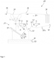
- FIG. 1 shows schematically the basic structure of a cleaning system 10 according to the invention for cleaning a batch-off system 100 in sections.
- a rubber sheet 99 is cooled and coated with an anti-adhesive agent, so that the rubber sheet 99 is transported further in a stacked or folded form 98 or can be processed.
- the batch-off system 100 has a coating device 90 .
- the coating device 90 is designed as a type of dip tank through which the rubber band 99 can be guided.
- An anti-adhesive solution L is located in the dip tank, so that the rubber web 99 can be coated with an appropriate anti-adhesive agent.
- the anti-adhesion agent solution is a mixture of water and anti-adhesion agent, the anti-adhesion agent being present, for example, in a concentration of 2 to 4% by weight, based on the total mixture.
- a mixture G containing anti-adhesive residues is collected in a collecting container 20a.
- the mixture G can contain, for example, rubber components or rubber particles.
- the collection container 20a also has a foam skimming device 30 .
- the foam skimming device 30 has at least one plate 32 inclined in relation to the horizontal 21 of the collecting container 20a and a movable spatula 33 .
- the spatula 33 can be moved horizontally in the moving direction D as shown by the arrow.
- a foam component S of the mixture G can be separated from the liquid components F of the mixture G with the aid of the horizontally movable gap 33 and transported to a foam collection container 40 .
- the first collecting container 20a is arranged below the coating device 90 in the vertical direction.
- the cleaning system 10 has a second collection container 20b.
- the second collection container 20b is arranged in the vertical direction below the dripping zone 95 of the batch-off system 100. Drops of the anti-adhesive agent can detach from the coated rubber strip 99 in the drip zone 95 .
- the second collection container 20b has an inclined wall 31 .
- the inclined wall 31 is part of the foam skimming device 30.
- a gap 33 is also formed in connection with the second collecting container 20b.
- the spatula 33 can also be moved in the direction of movement D. With a movement of the spatula 33 to the left, a foam component S can thus be transported to the foam collection container 40 .
- a liquid component F of the mixture G on the other hand, initially remains in the second collection container 20b.
- the inclined plate 32 is formed as a separate component.
- a foam skimming device 30 in order to form a foam skimming device 30, it is necessary to form a separate plate 32 in addition to forming a spatula 33.
- a wall of the collection container 20b itself is designed as an inclined surface or inclined wall 31 . It is therefore not necessary to form a separate plate here.
- a spray device 70 is preferably provided in the area of the second collecting container 20b, so that the drops of anti-adhesive agent collected by the second collecting container 20b can be diluted.
- the concentration of the anti-adhesive agent in the foam component S is around 50%, for example.
- the first collecting container 20a has a collecting section 23 in the bottom section 22 .
- the collection section 23 is designed to collect solids M of the mixture G.
- the collecting section 23 is formed, for example, by a cone-like shape of the base section 22 .
- the collection section 23 can also be referred to as a depression in the collection container 20a, in which solids M of the mixture G collect.
- the cleaning system 10 has a screw conveyor 50, with the help of which the solids M can be transported out of the first collecting container 20a.
- the solids M are preferably transported to a waste collection container 80 .
- This waste collection container can have a filter device, in particular a sieve separator 85 which is designed to separate residual liquid from the materials located in the waste collection container 80 .
- the solid M can be, for example, deposits of the precipitated anti-adhesive powder and rubber compound particles.
- the precipitated non-stick powder can be present in a concentration of about 75% at this stage.
- waste collection container 80 With the help of the waste collection container 80 and the additionally designed sieve separator 85, it is possible to separate residual liquid from collected waste materials again, so that this residual liquid can be returned to the batch-off system circuit.
- the foam component S of the foam collection container 40 is preferably also collected in the waste collection container 80 and separated again with the aid of the sieve separator 85 .
- the foam collection container 40 itself to have a filter device, in particular a sieve separator.
- This embodiment of the cleaning system 10 differs only in the alternative design of a centrifugal separator 60 instead of a screw conveyor 50.
- the solids M collected in the collecting container 20a can be separated again with regard to the liquid and solid components.
- the separated liquid fractions can be returned to the batch-off plant.
- the solids separated by means of the centrifugal separator 60 can be transported to the waste collection container 80 .
- a further separation or cleaning can be carried out here with the aid of a sieve separator 85 .
Landscapes
- Chemical & Material Sciences (AREA)
- Chemical Kinetics & Catalysis (AREA)
- Cleaning By Liquid Or Steam (AREA)
- Cleaning In General (AREA)
Applications Claiming Priority (1)
| Application Number | Priority Date | Filing Date | Title |
|---|---|---|---|
| DE102021214793.3A DE102021214793A1 (de) | 2021-12-21 | 2021-12-21 | Reinigungssystem zur abschnittsweisen Reinigung einer Batch-Off Anlage und Verfahren zur abschnittsweisen Reinigung einer Batch-Off Anlage |
Publications (2)
| Publication Number | Publication Date |
|---|---|
| EP4201501A1 true EP4201501A1 (fr) | 2023-06-28 |
| EP4201501B1 EP4201501B1 (fr) | 2025-04-23 |
Family
ID=84488388
Family Applications (1)
| Application Number | Title | Priority Date | Filing Date |
|---|---|---|---|
| EP22212723.5A Active EP4201501B1 (fr) | 2021-12-21 | 2022-12-12 | Installation de trempe par lots pourvue d'un système de nettoyage destiné au nettoyage par lot par zones de l'installation de trempe par lots et procédé de nettoyage par lot au moyen d'un système de nettoyage |
Country Status (2)
| Country | Link |
|---|---|
| EP (1) | EP4201501B1 (fr) |
| DE (1) | DE102021214793A1 (fr) |
Citations (4)
| Publication number | Priority date | Publication date | Assignee | Title |
|---|---|---|---|---|
| US4005019A (en) * | 1974-09-27 | 1977-01-25 | L.S. Love & Associates Limited | Gravitational separator |
| US20060243677A1 (en) * | 2005-04-27 | 2006-11-02 | Sheahan Donald T | Manure separator |
| KR100992430B1 (ko) * | 2010-03-12 | 2010-11-08 | 코오롱워터텍 주식회사 | 침전 장치 및 이를 포함하는 하ㆍ폐수 처리 장치 |
| WO2012047680A2 (fr) * | 2010-09-27 | 2012-04-12 | World Water Works, Inc. | Séparation de solides flottés |
-
2021
- 2021-12-21 DE DE102021214793.3A patent/DE102021214793A1/de active Pending
-
2022
- 2022-12-12 EP EP22212723.5A patent/EP4201501B1/fr active Active
Patent Citations (4)
| Publication number | Priority date | Publication date | Assignee | Title |
|---|---|---|---|---|
| US4005019A (en) * | 1974-09-27 | 1977-01-25 | L.S. Love & Associates Limited | Gravitational separator |
| US20060243677A1 (en) * | 2005-04-27 | 2006-11-02 | Sheahan Donald T | Manure separator |
| KR100992430B1 (ko) * | 2010-03-12 | 2010-11-08 | 코오롱워터텍 주식회사 | 침전 장치 및 이를 포함하는 하ㆍ폐수 처리 장치 |
| WO2012047680A2 (fr) * | 2010-09-27 | 2012-04-12 | World Water Works, Inc. | Séparation de solides flottés |
Also Published As
| Publication number | Publication date |
|---|---|
| EP4201501B1 (fr) | 2025-04-23 |
| DE102021214793A1 (de) | 2023-06-22 |
Similar Documents
| Publication | Publication Date | Title |
|---|---|---|
| DE3629947C2 (de) | Vorrichtung zur kontinuierlichen Abtrennung von Feststoffteilchen aus einer flüssigen Suspension | |
| DE3338171A1 (de) | Verfahren und vorrichtung zum trennen von emulsionen bzw. abtrennen von feststoffen aus einer suspension aus feststoffen und einer fluessigkeit mittels druck- bzw. turbo flotation | |
| EP0838264B1 (fr) | Procédé et goulotte à vibrations pour traiter un matériau à nettoyer | |
| EP4201501B1 (fr) | Installation de trempe par lots pourvue d'un système de nettoyage destiné au nettoyage par lot par zones de l'installation de trempe par lots et procédé de nettoyage par lot au moyen d'un système de nettoyage | |
| DE4402185A1 (de) | Verfahren und Vorrichtung zum Reinigen von Entfettungsmitteln | |
| DE10246540A1 (de) | Reinigungsvorrichtung und Verfahren zur Reinigung von Prozessgas einer Reflowlötanlage | |
| EP3730224A1 (fr) | Installation de dépoussiérage | |
| DE3342689C2 (de) | Filtervorrichtung zum Entfernen von Verunreinigungen aus Flüssigkeiten, insbesondere aus Dispersionsfarben | |
| DE102016108441B4 (de) | Verfahren und Vorrichtung zur Separation eines Stoffgemischs | |
| DE4310862C2 (de) | Verfahren zur Batteriesortierung | |
| DE2525550A1 (de) | Vorrichtung zur behandlung von abwaessern | |
| DE3513673A1 (de) | Verfahren und vorrichtung zum reinigen von mit kohlenwasserstoffen und insbesondere oel bzw. derivaten verschmutzten feststoffteilchen | |
| EP2170606A2 (fr) | Filtration pour machines d'impression | |
| WO2000026141A1 (fr) | Installation compacte pour l'epuration mecanique d'eaux usees | |
| DE2512291C2 (de) | Vorrichtung zum Abscheiden von Öl aus einem Öl-Wasser-Gemisch | |
| DE3200192A1 (de) | "spruehbehandlungsvorrichtung" | |
| DE4027880C2 (fr) | ||
| EP3248695A1 (fr) | Dispositif de tamisage | |
| CH653395A5 (de) | Verfahren zum betrieb einer gesamtanlage zur herstellung von papier sowie gesamtanlage zur ausfuehrung des verfahrens. | |
| DE69809947T2 (de) | Verfahren und vorrichtung zur trennung von schlammartigen materialen mittels einer feinblasigen belüftung | |
| DE10104552A1 (de) | Vorrichtung und Verfahren zum Abschälen eines Feststoffkuchens aus einer Zentrifugentrommel | |
| EP0401812A1 (fr) | Procédé et dispositif pour la préparation de tubercules | |
| DE102011011759A1 (de) | Magnetabscheidevorrichtung und Magnetabscheideverfahren zum Abscheiden von ferromagnetischen Teilchen aus einer damit belasteten Flüssigkeit | |
| DE19623027C1 (de) | Anlage zum Abscheiden und Trennen von leichteren und schwereren Fremdstoffen aus einem diese Stoffe enthaltenden Behandlungsgut, insbesondere zum Abscheiden von Fremdstoffen aus mit diesen belastetem Sand | |
| EP2422867B1 (fr) | Dispositif de séparation pour systèmes de toilettes sous vide |
Legal Events
| Date | Code | Title | Description |
|---|---|---|---|
| PUAI | Public reference made under article 153(3) epc to a published international application that has entered the european phase |
Free format text: ORIGINAL CODE: 0009012 |
|
| STAA | Information on the status of an ep patent application or granted ep patent |
Free format text: STATUS: THE APPLICATION HAS BEEN PUBLISHED |
|
| AK | Designated contracting states |
Kind code of ref document: A1 Designated state(s): AL AT BE BG CH CY CZ DE DK EE ES FI FR GB GR HR HU IE IS IT LI LT LU LV MC ME MK MT NL NO PL PT RO RS SE SI SK SM TR |
|
| STAA | Information on the status of an ep patent application or granted ep patent |
Free format text: STATUS: REQUEST FOR EXAMINATION WAS MADE |
|
| 17P | Request for examination filed |
Effective date: 20240102 |
|
| RBV | Designated contracting states (corrected) |
Designated state(s): AL AT BE BG CH CY CZ DE DK EE ES FI FR GB GR HR HU IE IS IT LI LT LU LV MC ME MK MT NL NO PL PT RO RS SE SI SK SM TR |
|
| RAP3 | Party data changed (applicant data changed or rights of an application transferred) |
Owner name: CONTINENTAL REIFEN DEUTSCHLAND GMBH |
|
| RIC1 | Information provided on ipc code assigned before grant |
Ipc: B01D 43/00 20060101ALI20241122BHEP Ipc: B01D 21/26 20060101ALI20241122BHEP Ipc: B01D 21/24 20060101ALI20241122BHEP Ipc: B01D 21/04 20060101ALI20241122BHEP Ipc: B01D 21/00 20060101AFI20241122BHEP |
|
| GRAP | Despatch of communication of intention to grant a patent |
Free format text: ORIGINAL CODE: EPIDOSNIGR1 |
|
| STAA | Information on the status of an ep patent application or granted ep patent |
Free format text: STATUS: GRANT OF PATENT IS INTENDED |
|
| INTG | Intention to grant announced |
Effective date: 20250108 |
|
| GRAS | Grant fee paid |
Free format text: ORIGINAL CODE: EPIDOSNIGR3 |
|
| GRAA | (expected) grant |
Free format text: ORIGINAL CODE: 0009210 |
|
| STAA | Information on the status of an ep patent application or granted ep patent |
Free format text: STATUS: THE PATENT HAS BEEN GRANTED |
|
| P01 | Opt-out of the competence of the unified patent court (upc) registered |
Free format text: CASE NUMBER: APP_10976/2025 Effective date: 20250306 |
|
| AK | Designated contracting states |
Kind code of ref document: B1 Designated state(s): AL AT BE BG CH CY CZ DE DK EE ES FI FR GB GR HR HU IE IS IT LI LT LU LV MC ME MK MT NL NO PL PT RO RS SE SI SK SM TR |
|
| REG | Reference to a national code |
Ref country code: GB Ref legal event code: FG4D Free format text: NOT ENGLISH |
|
| REG | Reference to a national code |
Ref country code: CH Ref legal event code: EP |
|
| REG | Reference to a national code |
Ref country code: DE Ref legal event code: R096 Ref document number: 502022003664 Country of ref document: DE |
|
| REG | Reference to a national code |
Ref country code: IE Ref legal event code: FG4D Free format text: LANGUAGE OF EP DOCUMENT: GERMAN |
|
| REG | Reference to a national code |
Ref country code: NL Ref legal event code: MP Effective date: 20250423 |
|
| PG25 | Lapsed in a contracting state [announced via postgrant information from national office to epo] |
Ref country code: NL Free format text: LAPSE BECAUSE OF FAILURE TO SUBMIT A TRANSLATION OF THE DESCRIPTION OR TO PAY THE FEE WITHIN THE PRESCRIBED TIME-LIMIT Effective date: 20250423 |
|
| PG25 | Lapsed in a contracting state [announced via postgrant information from national office to epo] |
Ref country code: FI Free format text: LAPSE BECAUSE OF FAILURE TO SUBMIT A TRANSLATION OF THE DESCRIPTION OR TO PAY THE FEE WITHIN THE PRESCRIBED TIME-LIMIT Effective date: 20250423 Ref country code: PT Free format text: LAPSE BECAUSE OF FAILURE TO SUBMIT A TRANSLATION OF THE DESCRIPTION OR TO PAY THE FEE WITHIN THE PRESCRIBED TIME-LIMIT Effective date: 20250825 Ref country code: ES Free format text: LAPSE BECAUSE OF FAILURE TO SUBMIT A TRANSLATION OF THE DESCRIPTION OR TO PAY THE FEE WITHIN THE PRESCRIBED TIME-LIMIT Effective date: 20250423 |
|
| REG | Reference to a national code |
Ref country code: LT Ref legal event code: MG9D |
|
| PG25 | Lapsed in a contracting state [announced via postgrant information from national office to epo] |
Ref country code: GR Free format text: LAPSE BECAUSE OF FAILURE TO SUBMIT A TRANSLATION OF THE DESCRIPTION OR TO PAY THE FEE WITHIN THE PRESCRIBED TIME-LIMIT Effective date: 20250724 Ref country code: NO Free format text: LAPSE BECAUSE OF FAILURE TO SUBMIT A TRANSLATION OF THE DESCRIPTION OR TO PAY THE FEE WITHIN THE PRESCRIBED TIME-LIMIT Effective date: 20250723 |
|
| PG25 | Lapsed in a contracting state [announced via postgrant information from national office to epo] |
Ref country code: PL Free format text: LAPSE BECAUSE OF FAILURE TO SUBMIT A TRANSLATION OF THE DESCRIPTION OR TO PAY THE FEE WITHIN THE PRESCRIBED TIME-LIMIT Effective date: 20250423 |
|
| PG25 | Lapsed in a contracting state [announced via postgrant information from national office to epo] |
Ref country code: BG Free format text: LAPSE BECAUSE OF FAILURE TO SUBMIT A TRANSLATION OF THE DESCRIPTION OR TO PAY THE FEE WITHIN THE PRESCRIBED TIME-LIMIT Effective date: 20250423 |
|
| PG25 | Lapsed in a contracting state [announced via postgrant information from national office to epo] |
Ref country code: HR Free format text: LAPSE BECAUSE OF FAILURE TO SUBMIT A TRANSLATION OF THE DESCRIPTION OR TO PAY THE FEE WITHIN THE PRESCRIBED TIME-LIMIT Effective date: 20250423 |
|
| PG25 | Lapsed in a contracting state [announced via postgrant information from national office to epo] |
Ref country code: RS Free format text: LAPSE BECAUSE OF FAILURE TO SUBMIT A TRANSLATION OF THE DESCRIPTION OR TO PAY THE FEE WITHIN THE PRESCRIBED TIME-LIMIT Effective date: 20250723 |
|
| PG25 | Lapsed in a contracting state [announced via postgrant information from national office to epo] |
Ref country code: IS Free format text: LAPSE BECAUSE OF FAILURE TO SUBMIT A TRANSLATION OF THE DESCRIPTION OR TO PAY THE FEE WITHIN THE PRESCRIBED TIME-LIMIT Effective date: 20250823 |
|
| PG25 | Lapsed in a contracting state [announced via postgrant information from national office to epo] |
Ref country code: LV Free format text: LAPSE BECAUSE OF FAILURE TO SUBMIT A TRANSLATION OF THE DESCRIPTION OR TO PAY THE FEE WITHIN THE PRESCRIBED TIME-LIMIT Effective date: 20250423 |
|
| PG25 | Lapsed in a contracting state [announced via postgrant information from national office to epo] |
Ref country code: SM Free format text: LAPSE BECAUSE OF FAILURE TO SUBMIT A TRANSLATION OF THE DESCRIPTION OR TO PAY THE FEE WITHIN THE PRESCRIBED TIME-LIMIT Effective date: 20250423 Ref country code: DK Free format text: LAPSE BECAUSE OF FAILURE TO SUBMIT A TRANSLATION OF THE DESCRIPTION OR TO PAY THE FEE WITHIN THE PRESCRIBED TIME-LIMIT Effective date: 20250423 |
|
| PGFP | Annual fee paid to national office [announced via postgrant information from national office to epo] |
Ref country code: AT Payment date: 20260113 Year of fee payment: 4 |
|
| PGFP | Annual fee paid to national office [announced via postgrant information from national office to epo] |
Ref country code: FR Payment date: 20251229 Year of fee payment: 4 |
|
| PG25 | Lapsed in a contracting state [announced via postgrant information from national office to epo] |
Ref country code: CZ Free format text: LAPSE BECAUSE OF FAILURE TO SUBMIT A TRANSLATION OF THE DESCRIPTION OR TO PAY THE FEE WITHIN THE PRESCRIBED TIME-LIMIT Effective date: 20250423 |
|
| PG25 | Lapsed in a contracting state [announced via postgrant information from national office to epo] |
Ref country code: EE Free format text: LAPSE BECAUSE OF FAILURE TO SUBMIT A TRANSLATION OF THE DESCRIPTION OR TO PAY THE FEE WITHIN THE PRESCRIBED TIME-LIMIT Effective date: 20250423 |
|
| REG | Reference to a national code |
Ref country code: DE Ref legal event code: R097 Ref document number: 502022003664 Country of ref document: DE |
|
| PG25 | Lapsed in a contracting state [announced via postgrant information from national office to epo] |
Ref country code: SK Free format text: LAPSE BECAUSE OF FAILURE TO SUBMIT A TRANSLATION OF THE DESCRIPTION OR TO PAY THE FEE WITHIN THE PRESCRIBED TIME-LIMIT Effective date: 20250423 |
|
| PG25 | Lapsed in a contracting state [announced via postgrant information from national office to epo] |
Ref country code: IT Free format text: LAPSE BECAUSE OF FAILURE TO SUBMIT A TRANSLATION OF THE DESCRIPTION OR TO PAY THE FEE WITHIN THE PRESCRIBED TIME-LIMIT Effective date: 20250423 |
|
| PLBE | No opposition filed within time limit |
Free format text: ORIGINAL CODE: 0009261 |
|
| STAA | Information on the status of an ep patent application or granted ep patent |
Free format text: STATUS: NO OPPOSITION FILED WITHIN TIME LIMIT |
|
| REG | Reference to a national code |
Ref country code: CH Ref legal event code: L10 Free format text: ST27 STATUS EVENT CODE: U-0-0-L10-L00 (AS PROVIDED BY THE NATIONAL OFFICE) Effective date: 20260304 |
|
| PG25 | Lapsed in a contracting state [announced via postgrant information from national office to epo] |
Ref country code: RO Free format text: LAPSE BECAUSE OF FAILURE TO SUBMIT A TRANSLATION OF THE DESCRIPTION OR TO PAY THE FEE WITHIN THE PRESCRIBED TIME-LIMIT Effective date: 20250423 |
|
| 26N | No opposition filed |
Effective date: 20260126 |
|
| PGFP | Annual fee paid to national office [announced via postgrant information from national office to epo] |
Ref country code: DE Payment date: 20251231 Year of fee payment: 4 |