EP4201787A1 - Système de direction pour un véhicule automobile - Google Patents
Système de direction pour un véhicule automobile Download PDFInfo
- Publication number
- EP4201787A1 EP4201787A1 EP22213720.0A EP22213720A EP4201787A1 EP 4201787 A1 EP4201787 A1 EP 4201787A1 EP 22213720 A EP22213720 A EP 22213720A EP 4201787 A1 EP4201787 A1 EP 4201787A1
- Authority
- EP
- European Patent Office
- Prior art keywords
- drive
- components
- steering column
- component
- drive wheel
- Prior art date
- Legal status (The legal status is an assumption and is not a legal conclusion. Google has not performed a legal analysis and makes no representation as to the accuracy of the status listed.)
- Withdrawn
Links
Images


Classifications
-
- B—PERFORMING OPERATIONS; TRANSPORTING
- B62—LAND VEHICLES FOR TRAVELLING OTHERWISE THAN ON RAILS
- B62D—MOTOR VEHICLES; TRAILERS
- B62D1/00—Steering controls, i.e. means for initiating a change of direction of the vehicle
- B62D1/02—Steering controls, i.e. means for initiating a change of direction of the vehicle vehicle-mounted
- B62D1/16—Steering columns
- B62D1/18—Steering columns yieldable or adjustable, e.g. tiltable
- B62D1/181—Steering columns yieldable or adjustable, e.g. tiltable with power actuated adjustment, e.g. with position memory
-
- B—PERFORMING OPERATIONS; TRANSPORTING
- B62—LAND VEHICLES FOR TRAVELLING OTHERWISE THAN ON RAILS
- B62D—MOTOR VEHICLES; TRAILERS
- B62D1/00—Steering controls, i.e. means for initiating a change of direction of the vehicle
- B62D1/02—Steering controls, i.e. means for initiating a change of direction of the vehicle vehicle-mounted
- B62D1/16—Steering columns
- B62D1/18—Steering columns yieldable or adjustable, e.g. tiltable
- B62D1/187—Steering columns yieldable or adjustable, e.g. tiltable with tilt adjustment; with tilt and axial adjustment
- B62D1/189—Steering columns yieldable or adjustable, e.g. tiltable with tilt adjustment; with tilt and axial adjustment the entire column being tiltable as a unit
Definitions
- the invention relates to a steering column for a motor vehicle, comprising at least two components which can be adjusted telescopically relative to one another in a longitudinal direction defined by a longitudinal axis, a motorized adjustment drive being operatively connected to the components for relative adjustment.
- a generic steering column is designed to be longitudinally adjustable in that it has at least two components that are telescopically adjustable relative to one another in a longitudinal direction defined by a longitudinal axis.
- a steering handle arranged on the rear or upper component with respect to the direction of travel for example a steering wheel that can be rotated about the longitudinal axis, can be positioned in an operating area.
- the components are retracted or pushed together, forward with respect to the direction of travel, they can be adjusted to set an optimal operating position for a manual steering intervention. If the components are pushed together as far forward as possible, the steering column can be stowed away. This stowage position can be set, for example, in autonomous driving, so that the vehicle interior can be released for other uses.
- the longitudinally adjustable components can be pushed together in the longitudinal direction in the event of a crash, which effectively prevents the components from penetrating into the interior of the passenger cell and causing injury to the occupants.
- the steering column has at least two components, for example telescopically arranged jacket pipes or the like, which form the telescopic elements of a jacket unit.
- the shell unit is held by a support unit on the vehicle body. Due to the fact that the jacket unit can optionally be adjusted relative to the support unit transversely to the longitudinal direction in a height direction, a height adjustment for adapting the operating position and for stowage can be made possible in addition to the longitudinal adjustment.
- a motor-adjustable steering column of the type mentioned, which has three telescopic elements that can be adjusted relative to one another by a motor-driven adjustment drive is known, for example, from EP 2 956 349 B1 known.
- the adjustment drive known from this has two spindle drives, each with a motorized drive unit, which each act on two telescopic elements that can be adjusted relative to one another.
- the disadvantage of this is the complex structure of the adjusting drive and the relatively large amount of space required and the high weight.
- a steering column for a motor vehicle comprising at least two components which can be adjusted telescopically relative to one another in a longitudinal direction defined by a longitudinal axis, with a motorized adjustment drive being operatively connected to the components for relative adjustment
- the adjustment drive is located on one of the Components about a drive axis lying transversely to the longitudinal axis rotatably mounted drive wheel, which engages at least on the other component in a rolling manner in the longitudinal direction, wherein the drive wheel can be driven by a motor about the drive axis to generate a linear adjustment force acting between the components in the longitudinal direction.
- a steering column for a motor vehicle comprising at least three components which can be adjusted telescopically relative to one another in a longitudinal direction defined by a longitudinal axis, with a motorized adjustment drive being operatively connected to the components for relative adjustment, in which it is provided that the adjustment drive a rotatably mounted on one of the components about a drive axis lying transversely to the longitudinal axis Having a drive wheel which can roll on at least one other component in the longitudinal direction, wherein the drive wheel can be driven by a motor about the drive axle to generate a linear adjustment force acting between the components in the longitudinal direction.
- a drive wheel that can be driven in rotation by a motor about its axis, this is the drive axis.
- the drive wheel is rotatably mounted on one of the components, for example a telescopic element, about the drive axis and is in operative engagement with at least one other component.
- the active engagement is formed in that the outer circumference of the drive wheel acts on the other component in a force-transmitting manner and can be rolled or rolled off on this, preferably with little or no slippage.
- a linear drive is realized in which the other component is carried along in the longitudinal direction according to the unrolled circumference by rotating the drive wheel by means of a motor drive unit.
- the drive torque of the drive wheel is converted into a linear drive force that acts as an adjustment force between the components.
- the motor-driven rotation of the drive wheel is converted into a longitudinal translation, ie a linear movement of the components relative to one another.
- the adjusting drive has a drive unit with an electric motor which, according to the invention, transmits its drive torque to the drive wheel via a drive shaft.
- the drive shaft can be formed by a transmission shaft of a transmission, for example as an output shaft of a reduction gear connected to the motor shaft of the motor.
- the transmission can be designed as a gear, belt, toothed belt or other transmission in order to be able to optimally transmit the drive torque to the drive wheel. It can also be adapted to the structural conditions.
- a direct drive can be implemented, in which the drive shaft is coupled directly to the motor shaft.
- the drive shaft can preferably be coupled to the drive wheel via a non-rotatable, torque-transmitting connection for introducing a drive torque.
- the drive wheel can be arranged directly in a rotationally fixed manner on the drive shaft.
- a transmission means can be a transmission element which is designed to transmit the driving force acting externally in the circumferential direction, which results from the driving torque introduced into the drive wheel and the diameter of the drive wheel, to the other component in the longitudinal direction.
- a transmission means can include a belt pulley, a friction wheel, a toothed wheel or chain wheel or the like, which can be formed on the drive wheel—preferably integrated—or is connected to it.
- the transmission means engages in a force-fitting and/or form-fitting manner in a correspondingly designed transmission means of the component, for converting the rotation of the drive wheel into a translation of a component that is in rolling engagement with the drive wheel.
- the drive wheel can be designed as a toothed wheel with externally circumferential toothing, which is in toothed engagement with a corresponding toothed rack on the component, which extends in the longitudinal direction.
- the advantage here is a defined, non-slip linear drive.
- a non-positive transmission can be realized in that the drive wheel is designed as a friction wheel with a friction surface that runs around the outside and interacts non-positively with a corresponding friction track on the component to be adjusted.
- the simple, reliable and compact design of the linear drive is advantageous.
- the drive wheel can also have various transmission and/or gearing means, each of which is in gear engagement with a different component.
- gears with different diameters can be provided which, for a given angle of rotation of the drive wheel, bring about different linear displacements of the components interacting therewith for a given rotation of the drive wheel.
- the drive wheel can have transmission means for coupling to a drive unit, which can advantageously be designed to be integrated.
- a drive unit which can advantageously be designed to be integrated.
- These can include, for example, gearing, a belt or toothed belt pulley or the like, which is drivingly connected to the motor.
- At least three components are preferably provided, it being possible for the three components to comprise at least a first component, a second component and a third component.
- the first component in which the drive wheel can be mounted, can be axial in one embodiment with respect to the longitudinal axis, ie, be arranged in a second component so as to be displaceable in the longitudinal direction.
- a third component can be arranged in the first component in a longitudinally displaceable manner.
- the second component can be arranged in an axially displaceable manner in the first component, and the third component can be arranged in the second component.
- the integration of the friction wheel according to the invention enables a structurally simple, small and light construction.
- Telescopic elements can comprise, as first, second and third components, telescoping jacket tubes nested in the longitudinal direction, or jacket tubes and intermediate elements arranged telescopically between them, for example rolling element cages, sliding bushes or the like arranged between the jacket tubes.
- a drive wheel according to the invention can be mounted on one of the telescopic elements and can be driven in rotation by means of a motor, preferably an electric drive unit, in order to telescopically adjust the telescopic elements relative to one another in the longitudinal direction.
- a steering spindle to be mounted in the jacket unit so that it can rotate about the longitudinal axis.
- a steering wheel can be attached to the rear end of the steering spindle as a manual steering handle.
- the steering spindle can be connected to a steering shaft, which has a mechanical connection to the wheels of the motor vehicle to be steered via a steering gear.
- it can be provided in a steer-by-wire steering system that the steering spindle interacts with rotary sensors or other input means, which convert a manually entered steering command into an electrical control signal, which is used to control electrical steering actuators that set a corresponding steering angle of the wheels .
- the advantage is the simple and compact design.
- the drive wheel is rotatably mounted on a component and is in operative engagement with at least two other components.
- the drive wheel can be arranged such that it can be driven in rotation by a motor, for example on a first component of a jacket unit, for example on a first jacket tube or on a rolling element cage.
- This first component can preferably be designed as an intermediate component which is arranged in a longitudinally adjustable, coaxially telescoping manner between a second and a third component.
- the second and third components can be an inner or inner casing tube arranged in the first casing tube comprise, and an outer casing coaxially receiving the first component.
- the outer circumference of the drive wheel can protrude radially over the first component in such a way that it comes into operative engagement outwards with the outer casing tube and at the same time comes into operative engagement inwards with the inner casing pipe.
- the drive wheel can have a gear wheel or friction wheel, which engages in a form-fitting manner in corresponding toothed racks on the other two components, or makes contact with corresponding friction tracks in a non-positive manner.
- a synchronization device can be arranged between at least two components for forced coupling of the relative movement of at least one third component in the longitudinal direction.
- the at least two components can be adjusted relative to one another by means of a drive wheel according to the invention.
- the synchronization device generates a movement of at least one further adjustable component which is mechanically positively coupled to the movement of the two driven components and which is not directly operatively connected to the drive wheel in terms of drive.
- Several other components can also be coupled to the synchronization device.
- two driven jacket tubes can be adjusted relative to one another by the drive wheel, and at least one other component, such as a third jacket tube, a rolling element cage or the like, can be positively coupled to the two driven jacket tubes via the synchronization device.
- the drive wheel is attached to a component that is spatially fixed in the longitudinal direction during adjustment, for example an outer casing tube of a steering column, and two or more telescopic elements that are adjustable relative thereto are coupled in a defined manner with regard to the longitudinal adjustment.
- a component that is spatially fixed in the longitudinal direction during adjustment for example an outer casing tube of a steering column
- two or more telescopic elements that are adjustable relative thereto are coupled in a defined manner with regard to the longitudinal adjustment.
- the synchronization device can have a synchronous wheel.
- a synchronous wheel can, for example, comprise a toothed wheel or a friction wheel, which is mounted on one component and is in rolling engagement with two other components. This is the relative Positioning of the three components is clearly determined in each adjustment state, and a relative adjustment of two components is forcibly converted into an adjustment of the third component by the linear coupling via the synchronous wheel.
- Such a synchronization device can be implemented in a structurally simple, reliable and compact manner.
- the synchronization device can have linear guide means. At least three components are forcibly coupled to one another via interacting guide elements such as linear guide tracks or rails and guide bodies or the like guided along them, which only allow clearly defined adjustment states. If the relative positioning of two components is changed during adjustment, an adjustment force is exerted on the third component or other components coupled thereto via the guide means, so that this is positioned in a defined manner relative to the two driven components.
- a drive unit has an electric motor and can preferably include a transmission coupled thereto.
- the drive unit can, for example, be mounted in a fixed manner in the longitudinal direction on a casing tube, in which a rotationally drivable drive wheel is mounted.
- the drive unit it is advantageous for the drive unit to be attached to a component which is stationary during adjustment in the longitudinal direction, for example an outer casing tube of a casing unit held by a support unit.
- the masses moved during adjustment can advantageously be kept as low as possible.
- the drive unit it is also possible for the drive unit to be attached to one component and to drive a drive wheel mounted on another component.
- Suitable transmission means can be provided for the transmission of the drive torque from the drive unit to the drive wheel, for example belts, toothed belts, chains, gear wheels or the like.
- a position sensor for detecting the position of the components. It can be provided that a position sensor interacts with the components. Such a position sensor can measure the actual current adjustment positions of the adjustable components, for example by optical or electronic measurement methods known per se, and output corresponding position signals. This enables automated monitoring and position control of the adjustment status, for example whether a preselected positioning is actually correct has been reached. In this way, incorrect positioning, which can occur, for example, due to slippage of a drive wheel designed as a friction wheel, can be detected and eliminated by readjustment with little effort.
- a further advantage is that a less precise or lighter dimensioned drive can be provided, with a position control fed back via the position sensor enabling a reproducible and precise adjustment at any time.
- FIG. 1 shows a steering column 1 according to the invention in a view at an angle from behind with respect to the direction of travel, which steering column has an actuating unit 2 .
- the control unit 2 includes a jacket unit 3, which has an outer jacket tube 31, an intermediate jacket tube 32 and an inner jacket tube 33, which are referred to collectively as jacket tubes 31, 32, and 33, and which represent adjustable components within the meaning of the invention. These are telescopically displaceable in the longitudinal direction, which corresponds to the axial direction of a longitudinal axis L, and are arranged coaxially within one another, as indicated by the double arrow.
- a steering spindle 4 is mounted in the shell unit 3 so that it can rotate about the longitudinal axis L and has a connecting section 41 at its rear end for attaching a steering wheel (not shown).
- figure 1 shows an adjustment position of the steering column 1 in an operating position in which the intermediate casing tube 32 and the inner casing tube 33 are at least partially moved out of the outer casing tube 31 backwards in the longitudinal direction in relation to the direction of travel of the motor vehicle - to the right in the drawing - so that a attached to the connecting portion 41 steering wheel is in the operating area for entering steering commands.
- figure 2 shows the same adjustment state, with the inner jacket tube being pulled out to the left due to the different perspective.
- the shell unit 3 is held in a two-part support unit 5, which has fastening means 51 in the form of openings for attachment to a vehicle body, not shown.
- An adjustment drive 6 has a drive unit 61 with an electric motor 62, the motor shaft 63 of which lies transversely to the longitudinal axis L.
- a belt wheel 64 is mounted on the motor shaft 63, around which a belt 65, which can be designed as a flat, V-belt or toothed belt, runs as a traction means.
- the adjusting drive 6 is attached to the intermediate casing tube 32 .
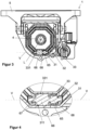
- figure 2 shows a cross section AA transverse to the longitudinal axis L through the steering column 1 according to Figure 2.
- a drive wheel 66 according to the invention is rotatably mounted in the intermediate jacket tube 32 about a drive axis V lying transversely to the longitudinal axis L.
- a circumferential friction surface 67 on its outer circumference which is a transmission medium within the meaning of the invention represents and can alternatively also have a ring gear 67
- the drive wheel 66 is in operative engagement with the outer jacket tube 31 and the inner jacket tube 33 .
- This is generated in that the friction surface 67 (or the ring gear) engages in a non-positive manner on corresponding friction surfaces 311 and 331 on the outer jacket tube 31 and on the inner jacket tube 33 in a rolling manner.
- a toothed ring is provided instead of the friction surface 67, corresponding toothed racks are provided instead of the friction surfaces 311 and 331, in which the toothed ring engages as a gear mechanism.
- a belt wheel 67 is connected in a rotationally locked manner to the drive wheel 66, for example formed in one piece as in the example shown. In any case, this results in a linear drive, which converts a rotation of the drive wheel 66 into a linear relative movement of the casing tubes 31, 32, 33.
- the belt wheel 67 is part of a belt drive in which the belt 65 driven by the motor 62 runs around the belt wheels 64 and 68 as a driving mechanism.
- the drive wheel 66 can be driven in rotation about the drive axis V by the motor 62 of the drive unit 61 via the belt drive.
- the friction surface 67 running around the outside of the drive wheel 66 or the ring gear is rolled on the corresponding friction surfaces 311 and 331, or the toothed racks, as a result of which the casing pipes 31 and 33 are moved apart relative to the intermediate casing pipe 32 supporting the drive wheel 66, depending on the direction of rotation of the drive wheel, see above that the steering column 1 is extended, and moved together accordingly in the reverse direction of rotation.
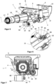
- FIGS Figures 1 to 4 a second embodiment of a steering column 1 according to the invention is shown, the view in figure 5 the view of figure 2 corresponds, and figure 7 a cross-section BB figure 5 shows.
- the adjusting drive 6 is shown in an enlarged detailed view seen from below.
- the drive wheel 66 is mounted in the outer jacket tube 31, to which the drive unit 61 is also attached.
- the drive gear 66 is in operative engagement with a friction surface 321 disposed and configured externally on the intermediate casing 32, analogous to the friction surface 331 on the inner casing 33 of the first embodiment, as described above.
- the friction surface 321 may also comprise a rack.
- a linear relative movement between the outer jacket tube 31 and the intermediate jacket tube 32 can be generated by rotating drive of the drive wheel 66, analogously to the above-described mode of operation of the first embodiment.
- a synchronization device 8 is provided, which is also referred to as a positioning device 8.
- FIG 8 the jacket unit 3 is shown individually for a better overview, in perspective and according to the adjustment state figure 1 .
- individual partial figures 8a, b, c, d and e individual partial sections of the casing pipes 31, 32, 33 have been cut open and left out and in each case provide a further view into the interior of the casing unit 3.
- FIG 8b the outer jacket tube 31 is partially omitted.
- a roller bearing unit 7 is arranged coaxially between the jacket tubes 31 and 32, which can be displaced telescopically in the longitudinal direction relative thereto and represents an intermediate element.
- the roller bearing unit 7 has a sleeve-shaped roller body cage 71, which is designed as a roller cage in the example shown, in which a plurality of rollers 72 are positioned as rolling bodies, each positioned in rows axially parallel to the longitudinal axis L and rotatably held.
- the rollers 72 roll on the outside of the outer casing pipe 31, i.e. on an inner surface of the outer casing pipe 31, and on the inside of the intermediate casing pipe 32, i.e. on an outer surface of the intermediate casing pipe 32, so that a linear roller bearing is formed in the longitudinal direction between the casing pipes 31 and 32 .
- roller bearing unit 7 is partially cut open and left out and gives a glimpse of the in Figure 8b the outer side of the intermediate jacket tube 32 covered by the rolling element cage 71 with the guide slot 83.
- the intermediate casing tube 32 is partially omitted. It can be seen that a second roller bearing unit 70 is arranged coaxially between the intermediate casing pipe 32 and the inner casing pipe 33.
- the roller bearing unit 70 has a sleeve-shaped roller body cage 73 in which a plurality of rollers 72 are held as roller bodies, each positioned in rows that are axially parallel to the longitudinal axis L and rotatably held.
- the rollers 72 roll on the outside of the intermediate casing pipe 32, i.e. on an inner surface of the intermediate casing pipe 32, and on the inside of the inner casing pipe 33, i.e. on an outer surface of the inner casing pipe 33, so that a linear roller bearing is formed in the longitudinal direction between the casing pipes 32 and 33 .
- roller bearing unit 70 is partially omitted and provides a view of the Figure 8d outside of the inner jacket tube 33 covered by the rolling element cage 73.
- a synchronization device 8 (positioning device 8) has, as elongated guide tracks, continuous guide slots 81, 82, 83, 84, 85 that are open radially with respect to the longitudinal axis L, with the guide slot 81 being arranged in the outer jacket tube 31, the guide slot 82 in the rolling element cage 71 of the Roller bearing unit 7, the guide slot 83 in the intermediate jacket tube 32, the guide slot 84 in the rolling element cage 73 of the roller bearing unit 70, and the guide slot 85 in the inner jacket tube 32.
- a guide pin 86 forms a guide body, all of which extends through all the guide slots 81, 82, 83, 84, 85, i.e. passing through them in the radial direction, transversely to the longitudinal axis L.
- the guide pin 86 is mounted in the guide slots 81, 82, 83, 84, 85 so that it can slide in the direction of the longitudinal extension, and is held radially in the slot openings and secured radially.
- the guide pin 86 is thus mounted in a floating manner with respect to each of the telescopic elements 31, 32, 33, 7, 70.
- the guide slot 81 is longer and inclined more flatly against the longitudinal axis L than the guide slot 82, which in turn is inclined more flatly than the guide slot 83 in the intermediate casing tube 32, which is perpendicular to the longitudinal axis L.
- the guide slots 84 and 85 are mirror images relative to the guide slots 82 and 81 , arranged with the opposite sign of inclination relative to the longitudinal axis L.
- All guide slots 81, 82, 83, 84, 85 intersect or overlap in a common overlapping section, where they are jointly penetrated by the guide pin 86.
- the guide pin 86 forms with each of the guide slots 81, 82, 83, 84, 85 a scenery tour.
- These link guides are forcibly coupled to one another by the common guide pin 86, ie the guide pin 86 can only move relative to all the guide slots 81, 82, 83, 84, 85 at the same time.
- the tubular jackets 31, 32, 33 and the roller bearing units 7, 70 are clearly forced to be positioned relative to one another in the longitudinal direction in each adjustment position passed through during the adjustment.
- a synchronized linear movement is generated when the jacket pipes 31 and 32 are moved relative to one another by the adjustment drive 8 according to the invention by means of the drive wheel 66 according to the invention.
- a motorized adjustment drive 600 can be provided, which in the example shown can be designed as a spindle drive. This has a spindle nut 601 and a threaded spindle 602 screwed into it, wherein the spindle nut 601 and the threaded spindle 602 can be driven in rotation by means of an electric motor. Because the threaded spindle 602 is supported on the jacket unit 3 and the spindle nut 601 on the support unit 5, the height position can be adjusted by the spindle drive.
Landscapes
- Engineering & Computer Science (AREA)
- Chemical & Material Sciences (AREA)
- Combustion & Propulsion (AREA)
- Transportation (AREA)
- Mechanical Engineering (AREA)
- Steering Controls (AREA)
Applications Claiming Priority (1)
| Application Number | Priority Date | Filing Date | Title |
|---|---|---|---|
| DE102021214797.6A DE102021214797A1 (de) | 2021-12-21 | 2021-12-21 | Lenksystem für ein Kraftfahrzeug |
Publications (1)
| Publication Number | Publication Date |
|---|---|
| EP4201787A1 true EP4201787A1 (fr) | 2023-06-28 |
Family
ID=84537101
Family Applications (1)
| Application Number | Title | Priority Date | Filing Date |
|---|---|---|---|
| EP22213720.0A Withdrawn EP4201787A1 (fr) | 2021-12-21 | 2022-12-15 | Système de direction pour un véhicule automobile |
Country Status (2)
| Country | Link |
|---|---|
| EP (1) | EP4201787A1 (fr) |
| DE (1) | DE102021214797A1 (fr) |
Citations (8)
| Publication number | Priority date | Publication date | Assignee | Title |
|---|---|---|---|---|
| US5737971A (en) * | 1996-08-05 | 1998-04-14 | General Motors Corporation | Motor vehicle steering column |
| US6220630B1 (en) * | 1996-09-16 | 2001-04-24 | Lars Sundholm | Steering wheel suspension system |
| US20060202463A1 (en) * | 2003-11-11 | 2006-09-14 | Jorg Schwarzbich | Telescoping steering shaft |
| EP2956349B1 (fr) | 2013-02-12 | 2018-12-12 | Robert Bosch Automotive Steering Vendôme | Dispositif d'escamotage d'une colonne de direction |
| EP3617035A1 (fr) * | 2018-08-28 | 2020-03-04 | Volkswagen Aktiengesellschaft | Colonne de direction par câbles réglable pour un véhicule automobile |
| DE102019114991A1 (de) * | 2019-06-04 | 2020-12-10 | Bayerische Motoren Werke Aktiengesellschaft | Lenksäulenabdeckung und Lenksäule mit einer Lenksäulenabdeckung |
| DE102020205728A1 (de) * | 2020-05-07 | 2021-11-11 | Thyssenkrupp Ag | Lenksäule für ein Kraftfahrzeug |
| WO2021224199A1 (fr) * | 2020-05-07 | 2021-11-11 | Thyssenkrupp Presta Ag | Colonne de direction pour véhicule automobile |
Family Cites Families (2)
| Publication number | Priority date | Publication date | Assignee | Title |
|---|---|---|---|---|
| US20180086378A1 (en) | 2016-09-27 | 2018-03-29 | Steering Solutions Ip Holding Corporation | Position detection system for a retractable steering column |
| DE102020205731A1 (de) | 2020-05-07 | 2021-11-11 | Thyssenkrupp Ag | Lenksäule für ein Kraftfahrzeug |
-
2021
- 2021-12-21 DE DE102021214797.6A patent/DE102021214797A1/de active Pending
-
2022
- 2022-12-15 EP EP22213720.0A patent/EP4201787A1/fr not_active Withdrawn
Patent Citations (8)
| Publication number | Priority date | Publication date | Assignee | Title |
|---|---|---|---|---|
| US5737971A (en) * | 1996-08-05 | 1998-04-14 | General Motors Corporation | Motor vehicle steering column |
| US6220630B1 (en) * | 1996-09-16 | 2001-04-24 | Lars Sundholm | Steering wheel suspension system |
| US20060202463A1 (en) * | 2003-11-11 | 2006-09-14 | Jorg Schwarzbich | Telescoping steering shaft |
| EP2956349B1 (fr) | 2013-02-12 | 2018-12-12 | Robert Bosch Automotive Steering Vendôme | Dispositif d'escamotage d'une colonne de direction |
| EP3617035A1 (fr) * | 2018-08-28 | 2020-03-04 | Volkswagen Aktiengesellschaft | Colonne de direction par câbles réglable pour un véhicule automobile |
| DE102019114991A1 (de) * | 2019-06-04 | 2020-12-10 | Bayerische Motoren Werke Aktiengesellschaft | Lenksäulenabdeckung und Lenksäule mit einer Lenksäulenabdeckung |
| DE102020205728A1 (de) * | 2020-05-07 | 2021-11-11 | Thyssenkrupp Ag | Lenksäule für ein Kraftfahrzeug |
| WO2021224199A1 (fr) * | 2020-05-07 | 2021-11-11 | Thyssenkrupp Presta Ag | Colonne de direction pour véhicule automobile |
Also Published As
| Publication number | Publication date |
|---|---|
| DE102021214797A1 (de) | 2023-06-22 |
Similar Documents
| Publication | Publication Date | Title |
|---|---|---|
| EP3743324B1 (fr) | Colonne de direction pour un véhicule automobile | |
| EP3817963B1 (fr) | Colonne de direction pour un véhicule automobile | |
| EP3829956B1 (fr) | Mécanisme de réglage destiné à une colonne de direction et colonne de direction pour véhicule automobile | |
| EP4146521B1 (fr) | Colonne de direction pour véhicule automobile | |
| EP3322632B1 (fr) | Actionneur à rétroaction pour un dispositif de direction | |
| DE19524196C1 (de) | Längsverstellvorrichtung an einem Mantelrohrteleskop einer Lenkspindel in einem Kraftfahrzeug | |
| DE102013014133B3 (de) | Lenkanschlag | |
| EP3844046B1 (fr) | Colonne de direction steer-by-wire à réglage électrique et véhicule automobile | |
| DE102019217961A1 (de) | Lenksäulenanordnung | |
| DE102022114095B3 (de) | Lenksäule mit hohler Teleskopwelle | |
| WO2010094318A2 (fr) | Unité de direction longitudinalement mobile pour un véhicule à moteur, comportant un support et une colonne de direction | |
| EP4054918B1 (fr) | Actionneur à rétroaction pour un système de direction d'un véhicule à moteur | |
| EP3577010B1 (fr) | Colonne de direction à positionnement motorisé pour véhicule automobile | |
| DE102019201621A1 (de) | Verstellbare Lenksäule für ein Kraftfahrzeug | |
| EP2208661A1 (fr) | Entraînement de rangement pour remorques de véhicules | |
| DE102010035270A1 (de) | Lenkvorrichtung für eine selbstfahrende Bau- oder Nutzmaschine sowie Bau- oder Nutzmaschine mit einer derartigen Lenkvorrichtung | |
| DE102020205728A1 (de) | Lenksäule für ein Kraftfahrzeug | |
| DE4243267A1 (de) | Lenkgetriebe | |
| EP3947107B1 (fr) | Colonne de direction pour un véhicule automobile | |
| DE102020205731A1 (de) | Lenksäule für ein Kraftfahrzeug | |
| DE102012203553A1 (de) | Übersetzungsgetriebe | |
| DE102009055025A1 (de) | Längenverstellbare Lenkbetätigungseinheit für ein Kraftfahrzeug mit einem Träger und mit einer Lenksäule | |
| DE3443625C2 (fr) | ||
| EP4245643B1 (fr) | Colonne de direction pour un véhicule automobile | |
| EP4201787A1 (fr) | Système de direction pour un véhicule automobile |
Legal Events
| Date | Code | Title | Description |
|---|---|---|---|
| PUAI | Public reference made under article 153(3) epc to a published international application that has entered the european phase |
Free format text: ORIGINAL CODE: 0009012 |
|
| STAA | Information on the status of an ep patent application or granted ep patent |
Free format text: STATUS: THE APPLICATION HAS BEEN PUBLISHED |
|
| AK | Designated contracting states |
Kind code of ref document: A1 Designated state(s): AL AT BE BG CH CY CZ DE DK EE ES FI FR GB GR HR HU IE IS IT LI LT LU LV MC ME MK MT NL NO PL PT RO RS SE SI SK SM TR |
|
| STAA | Information on the status of an ep patent application or granted ep patent |
Free format text: STATUS: THE APPLICATION IS DEEMED TO BE WITHDRAWN |
|
| 18D | Application deemed to be withdrawn |
Effective date: 20240103 |