EP4201819B1 - Satellite comprenant une antenne rayonnante deployable - Google Patents
Satellite comprenant une antenne rayonnante deployable Download PDFInfo
- Publication number
- EP4201819B1 EP4201819B1 EP22215632.5A EP22215632A EP4201819B1 EP 4201819 B1 EP4201819 B1 EP 4201819B1 EP 22215632 A EP22215632 A EP 22215632A EP 4201819 B1 EP4201819 B1 EP 4201819B1
- Authority
- EP
- European Patent Office
- Prior art keywords
- fluid
- radiating elements
- satellite
- radiating
- panel
- Prior art date
- Legal status (The legal status is an assumption and is not a legal conclusion. Google has not performed a legal analysis and makes no representation as to the accuracy of the status listed.)
- Active
Links
Images


Classifications
-
- B—PERFORMING OPERATIONS; TRANSPORTING
- B64—AIRCRAFT; AVIATION; COSMONAUTICS
- B64G—COSMONAUTICS; VEHICLES OR EQUIPMENT THEREFOR
- B64G1/00—Cosmonautic vehicles
- B64G1/22—Parts of, or equipment specially adapted for fitting in or to, cosmonautic vehicles
- B64G1/66—Arrangements or adaptations of apparatus or instruments, not otherwise provided for
-
- B—PERFORMING OPERATIONS; TRANSPORTING
- B64—AIRCRAFT; AVIATION; COSMONAUTICS
- B64G—COSMONAUTICS; VEHICLES OR EQUIPMENT THEREFOR
- B64G1/00—Cosmonautic vehicles
- B64G1/10—Artificial satellites; Systems of such satellites; Interplanetary vehicles
- B64G1/1007—Communications satellites
-
- B—PERFORMING OPERATIONS; TRANSPORTING
- B64—AIRCRAFT; AVIATION; COSMONAUTICS
- B64G—COSMONAUTICS; VEHICLES OR EQUIPMENT THEREFOR
- B64G1/00—Cosmonautic vehicles
- B64G1/22—Parts of, or equipment specially adapted for fitting in or to, cosmonautic vehicles
- B64G1/46—Arrangements or adaptations of devices for control of environment or living conditions
- B64G1/50—Arrangements or adaptations of devices for control of environment or living conditions for temperature control
- B64G1/506—Heat pipes
-
- H—ELECTRICITY
- H01—ELECTRIC ELEMENTS
- H01Q—ANTENNAS, i.e. RADIO AERIALS
- H01Q1/00—Details of, or arrangements associated with, antennas
- H01Q1/08—Means for collapsing antennas or parts thereof
-
- H—ELECTRICITY
- H01—ELECTRIC ELEMENTS
- H01Q—ANTENNAS, i.e. RADIO AERIALS
- H01Q1/00—Details of, or arrangements associated with, antennas
- H01Q1/27—Adaptation for use in or on movable bodies
- H01Q1/28—Adaptation for use in or on aircraft, missiles, satellites, or balloons
- H01Q1/288—Satellite antennas
-
- H—ELECTRICITY
- H01—ELECTRIC ELEMENTS
- H01Q—ANTENNAS, i.e. RADIO AERIALS
- H01Q21/00—Antenna arrays or systems
- H01Q21/0006—Particular feeding systems
- H01Q21/0025—Modular arrays
-
- H—ELECTRICITY
- H01—ELECTRIC ELEMENTS
- H01Q—ANTENNAS, i.e. RADIO AERIALS
- H01Q21/00—Antenna arrays or systems
- H01Q21/06—Arrays of individually energised antenna units similarly polarised and spaced apart
- H01Q21/061—Two dimensional planar arrays
- H01Q21/064—Two dimensional planar arrays using horn or slot aerials
Definitions
- the invention relates to satellites comprising a radiating antenna and, in particular, to a radiating antenna comprising a two-phase loop.
- Scanning radiating antennas often called active antennas for space applications, generally comprise a few dozen or a few hundred radiating elements associated with amplifiers and have surfaces of less than one square meter. These active radiating antennas can be easily assembled on Earth before being transported to space. These radiating antennas are also easily transportable on board rockets and/or space shuttles.
- part of the power consumed by the amplifiers and radiating elements is dissipated in the form of heat that must be evacuated, for example, by thermal control systems based on the use of passive fluidic components (such as heat pipes or capillary pumping loops). To evacuate the heat, these antennas require proximity between the amplifiers and radiators.
- US 2021/318074 A1 relates to a panel assembly for use with a spacecraft that includes a payload, a radiator panel, and a heat pipe.
- the payload is configured to generate waste heat during operation.
- the radiator panel is spaced from the payload and is configured to dissipate waste heat.
- the heat pipe is coupled to the payload and the radiator panel.
- the heat pipe includes a flexible portion to allow the radiator panel to move relative to the payload.
- the heat pipe is configured to transfer waste heat from the payload to the radiator panel US 6003817 A
- Deployable thermal panels are actively controlled throughout a satellite's orbit to ensure heat dissipation. By adjusting the angle of incidence of solar radiation on the panel and controlling the flow of a fluid through flexible heat-transport tubes, heat is charged and discharged to ensure the thermal stability of components that have special thermal requirements.
- An optional antenna panel on the nadir side of the satellite has a transmitting antenna side on one surface and a heat-radiating side on the opposite surface.
- the movements of the thermal panels are controlled to produce torques that oppose the disturbing torques.
- the invention proposes a satellite comprising a radiating antenna comprising a fixed panel and at least one deployable panel and a two-phase loop comprising flexible connections.
- the invention relates to a satellite that can be assembled and transported, even when the radiating antenna has a large surface area and high power.
- the two-phase loop makes it possible to recover the heat emitted by numerous radiating elements.
- the invention improves the situation by proposing a satellite comprising: a chassis, a radiating antenna comprising: radiating elements; amplifiers associated with the radiating elements, a base on which the radiating elements and the amplifiers are mounted, the base being configured to carry the radiating elements and the amplifiers and to evacuate heat emitted by the radiating elements and/or the amplifiers when they are in operation, the base comprising at least one fixed panel fixed to the chassis and at least one deployable panel articulated to the first panel, each of the panels carrying at least one of the radiating elements; and a two-phase loop in which a fluid circulates and configured to recover heat and transmit it to the base, the two-phase loop comprising: two portions, each fixed to one of the two panels of the base; and flexible connections comprising at least one flexible thermal channel and connecting the portions of the two-phase loop, the fluid circulating in the at least one flexible thermal channel.
- the deployable panel is configured to have a deployed position when the satellite is in service and a stowed position when the satellite is in transport.
- the two-phase loop comprises a pump configured to circulate the fluid with a flow rate greater than a predetermined value and a two-phase state in each panel and at least one condenser configured to remove heat from the fluid.
- the radiating antenna has a surface area ranging from 8 m 2 to 20 m 2 .
- the fluid is a heat transfer fluid configured for use in a liquid state and in a two-phase state.
- the heat transfer fluid is ammonia.
- the flexible connections include channels configured to transmit signals carrying an electromagnetic wave emitted and/or received by the radiating elements.
- FIG. 1 illustrates an example of a satellite 100 seen in profile.
- the satellite comprises a chassis 102 and a radiating antenna 120.
- the radiating antenna comprises radiating elements 110.
- the radiating elements 110 may be horn antennas allowing the reception of terrestrial signals or the transmission of signals to Earth.
- the radiating elements are associated with amplifiers 103 making it possible to amplify the signals received and/or transmitted by the radiating elements 110.
- each of the radiating elements 110 may be associated with an amplifier 103.
- the radiating antenna comprises a base 104 on which the radiating elements 110 and the amplifiers 103 are mounted.
- the base 104 is configured to carry the radiating elements 110 and to dissipate heat emitted by the radiating elements 110 and/or the amplifiers 103 when they are in operation.
- the base 104 comprises at least one fixed panel 104a fixed to the frame and at least one deployable panel 104b, 104c hinged to the fixed panel 104a, each of the panels carrying at least one of the radiating elements 110 and the associated amplifier 103.
- the radiating antenna comprises two deployable panels 104b, 104c, each being hinged to the fixed panel 104a.
- the radiating antenna may comprise a single deployable panel.
- the deployable panels 104b, 104c have a deployed position.
- the Figure 2 illustrates the satellite 100 seen in profile, deployable panels 104b, 104c having a folded position.
- the deployable panels 104b, 104c are configured to have a deployed position which can be used when the satellite 100 is in service and a folded position when the satellite 100 is in transport.
- the folded position makes it possible, in the case of large radiating antennas (for example, having a surface area greater than 8 m 2 ) to facilitate the transport of the satellite on board rockets and/or space shuttles by optimizing the space required for transport.
- only one of the two deployable panels 104b, 104c can be in the deployed position when the satellite is in use.
- the chassis can include hinged attachment mechanisms between the deployable panels and the fixed panel, allowing the deployable panels to move from the folded to the deployed position.
- the radiating antenna 120 comprises a two-phase loop 106 in which a heat transfer fluid circulates.
- the fluid may be, for example, ammonia, pentafluoropropane or tetrafluoroethane (“freon” type, products sold by the company DuPont de Nemours).
- the two-phase loop 106 is configured to recover the heat emitted by the radiating elements 110 and/or the amplifiers 103 and transmitted to the base 104.
- the two-phase loop 106 may be configured to recover the heat also emitted by amplifiers and transmitted to the base 104.
- the two-phase loop 106 comprises three portions 106a, 106b, 106c, each attached to one of the three panels 104a, 104b, 104c of the base 104.
- the two-phase loop 106 comprises flexible connections 108 comprising at least one flexible thermal channel and connecting the three portions 106a, 106b, 106c of the two-phase loop 106, the fluid circulating in the flexible thermal channel.
- the flexible connections 108 connect the portion of the two-phase loop 106 attached to the first deployable panel 104b with the portion of the two-phase loop 106 attached to the fixed panel 104a.
- flexible connections 108 connect the portion of the two-phase loop 106 attached to the second deployable panel 104c with the portion of the two-phase loop 106 attached to the fixed panel 104a.
- the radiating antenna 120 may comprise a single deployable panel.
- the two-phase loop 106 may comprise only two portions, each attached to one of the two panels of the base 104 (i.e., the deployable panel and the fixed panel 104a) and the flexible connections connect the portion of the two-phase loop 106 attached to the deployable panel with the portion of the two-phase loop 106 attached to the fixed panel 104a. More generally, comprises as many deployable panels as necessary for its operation.
- the various deployable panels can each be hinged to the fixed panel 104a or even hinged to another deployable panel.
- Flexible connections 108 are provided at each joint comprising at least one thermal channel. All of these channels allow, within the same two-phase loop, the circulation of the heat transfer fluid in each of the panels, fixed and deployable.
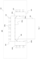
- FIG. 3 illustrates the radiating antenna 120 seen from above and with the deployable panels 104b, 104c in the deployed position.
- the two-phase loop 106 comprises channels shown in dotted lines allowing the fluid to circulate and recover the heat from each of the radiating elements 110 and the associated amplifier 103.
- the channels are arranged on the lower face of the radiating antenna 120 (i.e. on the face of the base 104 in contact with the chassis 102). It is also possible to arrange the channels on the opposite face of the base, face on which the radiating elements 110 and the amplifiers 103 are arranged. It is also possible to embed the channels in the base 104.
- the channels can run along the edges of the base 104 and advantageously opposite each of the radiating elements 110 and amplifiers 103 in order to best ensure temperature homogeneity over the entire surface of the base 104.
- the fluid circulates in the radiating antenna 120 between a fluid inlet 112 and a fluid outlet 114.
- the two-phase loop 106 of the present invention is configured so that, when the fluid circulates in the two-phase loop 106 close to the radiating elements 110 and recovers heat from the radiating elements 110, the temperature of the fluid increases until it reaches its saturation temperature.
- several solutions can be proposed such as the use of heaters, the regulation of the flow rate in the panels or the use of a heat exchanger between an inlet and an outlet of the panels.
- the two-phase loop therefore makes it possible to recover the heat emitted by the radiating elements and the amplifiers 103, even for a very large number of radiating elements (for example, thousands) with constant exchange conditions and, therefore, temperature homogeneity of the radiating elements (with a difference of less than 10°C between the radiating elements), which is necessary to guarantee the radiofrequency performance of the radiating antenna.
- the two-phase loop 106 may include a heat exchanger (not shown) between an outlet of the pump 114 and the inlet 112 in order to increase the temperature of the fluid to its saturation temperature before reaching the radiating elements 110.
- the two-phase loop 106 may include one or more temperature sensors for measuring the temperature of the fluid at one or more locations and thus verifying whether the temperature of the fluid is indeed above the saturation temperature at the radiating antenna 120. Similarly, one or more temperature sensors may ensure that the temperature of the fluid is below the saturation temperature before circulating in the pump (the pump operating with a fluid in the liquid state.
- the two-phase loop 106 comprises at least one condenser 116 configured to remove heat from the fluid.
- a condenser 116 is shown.
- two or more condensers may be used.
- the condenser 116 may be thermally linked to one or more radiators for removing heat from the radiating elements 110 and associated amplifiers recovered by the fluid to the outside of the satellite 100.
- the condenser 116 allows the heat transfer fluid to be condensed and then the temperature of the fluid to be reduced below its saturation temperature in order to return to the liquid state.
- the fluid may therefore be in the liquid state at an outlet of the condenser 116 in order to be in the liquid state while circulating in the pump 114.
- the radiating antenna 120 comprises two deployable panels 104b, 104c which are in the deployed position.
- the flexible connections 108 make it possible to connect the portion 106a of the two-phase loop 106 which is placed on the fixed panel 104a with the portion 106b of the two-phase loop 106 which is placed on the deployable panel 104b.
- the flexible connections 108 make it possible to connect the portion 106a of the two-phase loop 106 which is placed on the fixed panel 104a with the portion 106b of the two-phase loop 106 which is placed on the deployable panel 104c.
- the flexible connections 108 comprise channels configured to transmit signals carrying an electromagnetic wave emitted and/or received by the radiating elements 110.
- the flexible connections 108 in addition to transmitting the fluid through the two-phase loop 106, can transmit optical, electrical, etc. signals allowing the operation of the radiating antenna 120.
- the pump is used to circulate the fluid with a two-phase state in each panel 104a, 104b, 104c.
- other systems may be used to circulate the fluid with a two-phase state in each panel, such as a compressor.
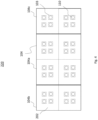
- FIG. 4 illustrates another example of a radiating antenna 220 seen from above and with the deployable panels 104b, 104c in the deployed position.
- the two-phase loop 106 is not shown.
- the two-phase loop 106 described above with regard to the Figure 3 can be used with the 220 radiating antenna.
- the antenna radiating antenna 220 comprises tiles 202 fixed on the base 104. Each tile 202 comprises radiating elements 110. Each tile 202 is connected to the adjacent tile(s) so as to form a radiating antenna 220 having the functionalities of a formed radiating antenna not being divided into different tiles.
- the tiles 202 make it possible to facilitate the manufacture and assembly of large radiating antennas.
- the radiating antenna 220 can have an area ranging from 8 m 2 to 20 m 2 .
- the manufacture and assembly of the radiating antenna 220 can be facilitated.
- the invention has been illustrated and described in detail using a preferred embodiment, the invention is not limited to the disclosed examples. Other variations may be deduced by those skilled in the art without departing from the scope of protection of the claimed invention.
- the radiating antenna 120, 220 may comprise several hundred to several thousand radiating elements 110.
- the invention has been illustrated with two deployable panels.
- the satellite may comprise only one deployable panel.
- an amplifier is associated with a radiating element.
- an amplifier may be associated with several radiating elements.
- the radiating and amplifier elements are mounted on the upper face of the panels and the two-phase loop is on the lower face of the panels.
- the radiating elements may be fixed on the upper face of the panels, the amplifiers placed on trays placed inside the panels, and whose planes are orthogonal to the upper and lower faces of the panels.
Landscapes
- Engineering & Computer Science (AREA)
- Remote Sensing (AREA)
- Aviation & Aerospace Engineering (AREA)
- Physics & Mathematics (AREA)
- Astronomy & Astrophysics (AREA)
- General Physics & Mathematics (AREA)
- Health & Medical Sciences (AREA)
- Life Sciences & Earth Sciences (AREA)
- Biodiversity & Conservation Biology (AREA)
- Environmental & Geological Engineering (AREA)
- Environmental Sciences (AREA)
- General Health & Medical Sciences (AREA)
- Toxicology (AREA)
- Details Of Aerials (AREA)
Description
- L'invention concerne des satellites comprenant une antenne rayonnante et, en particulier, une antenne rayonnante comprenant une boucle diphasique.
- Les antennes rayonnantes à balayage, souvent appelées antennes actives pour applications spatiales comprennent en général quelques dizaines ou quelques centaines d'éléments rayonnants associés à des amplificateurs et ont des surfaces de moins de un mètre carré. Ces antennes rayonnantes actives peuvent être assemblées facilement sur Terre avant d'être transportées vers l'espace. Ces antennes rayonnantes sont également facilement transportables à bord de fusées et ou navettes spatiales. De plus, lors de l'utilisation, une partie de la puissance consommée par les amplificateurs et éléments rayonnants est dissipée sous forme de chaleur qu'il est nécessaire d'évacuer par exemple par systèmes de contrôle thermique basés sur l'utilisation de composants fluidiques passifs (tels que des caloducs ou des boucles à pompage capillaire). Pour évacuer la chaleur, ces antennes nécessitent une proximité entre les amplificateurs et des radiateurs. Cependant, pour des satellites ayant des applications en télécommunication, afin d'assurer des hauts débits et ultra hauts débits, les antennes actives requièrent une large surface et nécessitent une consommation de fortes puissances, engendrant ainsi une dissipation de fortes puissances. Ainsi, pour des applications nécessitant des antennes ayant une surface plus grande (par exemple, supérieure à 8 m2) et de nombreux éléments rayonnants (par exemple, plusieurs milliers), les systèmes connus comprenant des antennes rayonnantes ne permettent pas de garantir une température homogène sur toute leur surface lorsque la puissance émise est importante. De plus, les antennes de large surface et comprenant de nombreux éléments rayonnants sont difficilement transportables à bord de fusées et ou navettes spatiales, difficilement assemblables et dissipent de forte puissances (par exemple supérieure à 10 kW) qui ne peuvent pas être récupérés par les systèmes de contrôle thermique actuels.
- Enfin, la notion d'homogénéité en température entre les différents éléments rayonnants est un paramètre clé pour garantir la performance radiofréquence de systèmes comprenant des antennes rayonnantes. Un gradient de 5 à 10°C permet de garantir cette performance.
US 2021/318074 A1 concerne un ensemble panneau destiné à être utilisé avec un engin spatial qui comprend une charge utile, un panneau de radiateur et un caloduc. La charge utile est configurée pour générer de la chaleur perdue pendant un fonctionnement. Le panneau de radiateur est espacé de la charge utile et est configuré pour dissiper de la chaleur perdue. Le caloduc est accouplé à la charge utile et au panneau de radiateur. Le caloduc comprend une partie souple pour permettre au panneau de radiateur de se déplacer par rapport à la charge utile. En outre, le caloduc est configuré pour transférer de la chaleur perdue de la charge utile au panneau de radiateur
US 6003817 A concernce des panneaux thermiques pouvant être déployés sont commandés de manière active tout au long de l'orbite d'un satellite afin d'assurer la dissipation thermique. Par ajustement de l'angle d'incidence des rayons solaires sur le panneau et par commande de l'écoulement d'un fluide dans des tubes souples de transport de chaleur, on charge et on décharge de la chaleur de manière à assurer la stabilité thermique de composants qui présentent des exigences spéciales du point de vue thermique. Un panneau d'antenne facultatif se trouvant sur le côté nadir du satellite présente un côté antenne de transmission sur une surface et un côté de rayonnement thermique sur la surface opposée. De plus, les déplacements des panneaux thermiques sont commandés de façon que soient produits des couples s'opposant aux couples perturbateurs. - Afin de pallier les inconvénients des satellites comprenant des antennes rayonnantes de grandes surfaces (par exemple, supérieure à 8 m2) et ayant de nombreux éléments rayonnants (par exemple, plusieurs milliers), l'invention propose un satellite comprenant une antenne rayonnante comprenant un panneau fixe et au moins un panneau déployable et une boucle diphasique comprenant des raccordements flexibles.
- A cet effet, l'invention a pour objet un satellite pouvant être assemblé et transporté, même lorsque l'antenne rayonnante a une grande surface et une forte puissance. De plus, la boucle diphasique permet de récupérer la chaleur émise par de nombreux éléments rayonnants.
- L'invention vient à améliorer la situation en proposant un satellite comprenant : un châssis, une antenne rayonnante comprenant : des éléments rayonnants ; des amplificateurs associés aux éléments rayonnants, une embase sur laquelle les éléments rayonnants et les amplificateurs sont montés, l'embase étant configurée pour porter les éléments rayonnants et les amplificateurs et pour évacuer de la chaleur émise par les éléments rayonnants et/ou les amplificateurs lorsqu'ils sont en fonctionnement, l'embase comprenant au moins un panneau fixe fixé au châssis et au moins un panneau déployable articulé au premier panneau, chacun des panneaux portant au moins un des éléments rayonnants ; et une boucle diphasique dans laquelle circule un fluide et configurée pour récupérer la chaleur et transmise à l'embase, la boucle diphasique comprenant : deux portions, chacune fixée à l'un des deux panneaux de l'embase ; et des raccordements flexibles comprenant au moins un canal thermique flexible et connectant les portions de la boucle diphasique, le fluide circulant dans le au moins un canal thermique flexible.
- Dans un mode de réalisation, le panneau déployable est configuré pour avoir une position déployée lorsque le satellite est en service et une position repliée lorsque le satellite est en transport.
- Dans un mode de réalisation, la boucle diphasique comprend une pompe configurée pour faire circuler le fluide avec un débit supérieur à une valeur prédéterminée et un état diphasique dans chaque panneau et au moins un condenseur configuré pour évacuer de la chaleur du fluide.
- Dans un mode de réalisation, l'antenne rayonnante a une surface allant de 8 m2 à 20 m2.
- Dans un mode de réalisation, le fluide est un fluide caloporteur configuré pour une utilisation à l'état liquide et à l'état diphasique.
- Dans un mode de réalisation, le fluide caloporteur est de l'ammoniac.
- Dans un mode de réalisation, les raccordements flexibles comprennent des canaux configurés pour transmettre des signaux véhiculant une onde électromagnétique émise et/ou reçue par les éléments rayonnants.
- L'invention sera mieux comprise et d'autres avantages apparaîtront à la lecture de la description qui va suivre donnée à titre non limitatif et grâce aux figures parmi lesquelles :
- La
figure 1 illustre un exemple de satellite comprenant une antenne rayonnante en position déployée vu de profil ; - La
figure 2 illustre un exemple de satellite comprenant une antenne rayonnante en position repliée vu de profil ; - La
figure 3 illustre un exemple d'antenne rayonnante en position déployée vu de dessus ; et - La
figure 4 illustre un autre exemple d'antenne rayonnante en position déployée vu de dessus. - La
figure 1 illustre un exemple de satellite 100 vu de profil. Le satellite comprend un châssis 102 et une antenne rayonnante 120. L'antenne rayonnante comprend des éléments rayonnants 110. Par exemple, les éléments rayonnants 110 peuvent être des antennes cornets permettant la réception de signaux terrestres ou la transmission de signaux vers la Terre. Les éléments rayonnants sont associés à des amplificateurs 103 permettant d'amplifier les signaux reçus et/ou transmis par les éléments rayonnants 110. Par exemple, chacun des éléments rayonnants 110 peut être associé à un amplificateur 103. - De plus, l'antenne rayonnante comprend une embase 104 sur laquelle les éléments rayonnants 110 et les amplificateurs 103 sont montés. L'embase 104 est configurée pour porter les éléments rayonnants 110 et pour évacuer de la chaleur émise par les éléments rayonnants 110 et/ou les amplificateurs 103 lorsqu'ils sont en fonctionnement. L'embase 104 comprend au moins un panneau fixe 104a fixé au châssis et au moins un panneau déployable 104b, 104c articulé au panneau fixe 104a, chacun des panneaux portant au moins un des éléments rayonnants 110 et l'amplificateur 103 associé. Dans l'exemple illustré dans la
figure 1 , l'antenne rayonnante comprend deux panneaux déployables 104b, 104c, chacun étant articulé au panneau fixe 104a. Dans un autre exemple, l'antenne rayonnante peut comprendre un seul panneau déployable. - Dans la
figure 1 , les panneaux déployables 104b, 104c ont une position déployée. Lafigure 2 illustre le satellite 100 vu de profil, panneaux déployables 104b, 104c ayant une position repliée. En effet, les panneaux déployables 104b, 104c sont configurés pour avoir une position déployée qui peut être utilisée lorsque le satellite 100 est en service et une position repliée lorsque le satellite 100 est en transport. La position repliée permet, dans le cas des antennes rayonnantes de grande taille (par exemple, ayant une surface supérieure à 8 m2) de faciliter le transport du satellite à bord des fusées et ou navettes spatiales en optimisant l'espace nécessaire pour le transport. Dans un exemple, un seul des deux panneaux déployables 104b, 104c peut être en position déployée lorsque le satellite est utilisé. Le châssis peut comprendre des mécanismes de fixation articulés entre les panneaux déployables et le panneau fixe, permettant aux panneaux déployables de passer de la position repliée à déployée. - De plus, l'antenne rayonnante 120 comprend une boucle diphasique 106 dans laquelle circule un fluide caloporteur. Le fluide peut être par exemple de l'ammoniac pentafluoropropane ou tetrafluoroethane (type « fréon », produits vendus par la société DuPont de Nemours). La boucle diphasique 106 est configurée pour récupérer la chaleur émise par les éléments rayonnants 110 et/ou les amplificateurs 103 et transmise à l'embase 104. Dans un exemple, la boucle diphasique 106 peut être configurée pour récupérer la chaleur émise également par des amplificateurs et transmise à l'embase 104. Dans l'exemple de la
figure 1 , la boucle diphasique 106 comprend trois portions 106a, 106b, 106c, chacune fixée à l'un des trois panneaux 104a, 104b, 104c de l'embase 104. De plus, la boucle diphasique 106 comprend des raccordements flexibles 108 comprenant au moins un canal thermique flexible et connectant les trois portions 106a, 106b, 106c de la boucle diphasique 106, le fluide circulant dans le canal thermique flexible. En particulier, les raccordements flexibles 108 connectent la portion de la boucle diphasique 106 fixée sur le premier panneau déployable 104b avec la portion de la boucle diphasique 106 fixée sur le panneau fixe 104a. De même, des raccordements flexibles 108 connectent la portion de la boucle diphasique 106 fixée sur le deuxième panneau déployable 104c avec la portion de la boucle diphasique 106 fixée sur le panneau fixe 104a. Dans un autre exemple, l'antenne rayonnante 120 peut comprendre un seul panneau déployable. Ainsi, la boucle diphasique 106 peut comprendre seulement deux portions, chacune fixée à l'un des deux panneaux de l'embase 104 (c'est-à-dire le panneau déployable et le panneau fixe 104a) et les raccordements flexibles connectent la portion de la boucle diphasique 106 fixée sur le panneau déployable avec la portion de la boucle diphasique 106 fixée sur le panneau fixe 104a. De façon plus générale, comprend autant de panneaux déployables que nécessaire à son fonctionnement. Les différents panneaux déployables peuvent être articulés chacun au panneau fixe 104a ou même articulés à un autre panneau déployable. Des raccordements flexibles 108 sont prévus au niveau de chaque articulation comprend au moins un canal thermique. L'ensemble de ces canaux permet, au sein d'une même boucle diphasique, la circulation du fluide caloporteur dans chacun des panneaux, fixe et déployable. - La
figure 3 illustre l'antenne rayonnante 120 vu de dessus et avec les panneaux déployables 104b, 104c en position déployée. Dans cet exemple, la boucle diphasique 106 comprend des canaux représentés en traits pointillés permettant au fluide de circuler et de récupérer la chaleur de chacun des éléments rayonnants 110 et l'amplificateur 103 associé. Dans cet exemple, les canaux sont disposés sur la face inférieure de l'antenne rayonnante 120 (c'est-à-dire sur la face de l'embase 104 en contact avec le châssis 102). Il est également possible de disposer les canaux sur la face opposée de l'embase, face sur laquelle sont disposés les éléments rayonnants 110 et les amplificateurs 103. Il est également possible de noyer les canaux dans l'embase 104. Les canaux peuvent circuler le long des bords de l'embase 104 et avantageusement en regard de chacun des éléments rayonnants 110 et amplificateurs 103 afin d'assurer au mieux l'homogénéité de la température sur toute la surface de l'embase 104. Comme illustré dans lafigure 3 , le fluide circule dans l'antenne rayonnante 120 entre une entrée 112 du fluide et une sortie 114 du fluide. - La boucle diphasique 106 comprend une pompe 114 configurée pour faire circuler le fluide avec un débit supérieur à une valeur prédéterminée et un état diphasique dans chaque panneau 104a, 104b, 104c. La valeur prédéterminée peut dépendre par exemple de la pompe, du fluide, d'une dimension de la boucle diphasique. En particulier, tout type de pompe 114 peut être utilisé pour faire circuler le fluide dans la boucle diphasique 106, et le fluide circulant dans la pompe est à l'état liquide. Cependant, un état diphasique du fluide (qui peut être par exemple de l'ammoniaque) permet de garantir un coefficient d'échange thermique élevé entre le fluide et les éléments rayonnants 110 et/ou amplificateurs 103. Au contraire, lorsque le fluide est à l'état liquide, le coefficient d'échange thermique est faible et la température du fluide augmente lorsqu'il récupère de la chaleur des éléments rayonnants 110 et amplificateurs 103. Ainsi, la boucle diphasique 106 de la présente invention est configurée pour que, lorsque le fluide circule dans la boucle diphasique 106 proche des éléments rayonnants 110 et récupère la chaleur des éléments rayonnants 110, la température du fluide augmente jusqu'à atteindre sa température de saturation. Pour avoir un état diphasique sous chaque panneau 104a, 104b, 104c, plusieurs solutions peuvent être proposées comme l'utilisation de réchauffeurs, la régulation du débit dans les panneaux ou l'utilisation d'un échangeur de chaleur entre une entrée et une sortie des panneaux. Ainsi, en ayant un fluide à l'état diphasique permettant de récupérer la chaleur émise par les éléments rayonnants et les amplificateurs 103, il est possible de récupérer de fortes puissances de dissipations (par exemple, supérieure à 10 kW) avec une température de fluide qui reste constante tant que le fluide est à l'état diphasique. La boucle diphasique permet donc de récupérer la chaleur émise par les éléments rayonnants et les amplificateurs 103, même pour un très grand nombre d'éléments rayonnants (par exemple, des milliers) avec des conditions d'échange constantes et, donc une homogénéité en température des éléments rayonnants (avec un écart de moins de 10°C entre les éléments rayonnants), ce qui est nécessaire pour garantir la performance radiofréquence de l'antenne rayonnante.
- Dans un exemple, la boucle diphasique 106 peut comprendre un échangeur de chaleur (non représenté) entre une sortie de la pompe 114 et l'entrée 112 afin d'augmenter la température du fluide jusqu'à sa température de saturation avant d'atteindre les éléments rayonnants 110.
- Dans un autre exemple, la boucle diphasique 106 peut comprendre un ou plusieurs capteurs de température permettant de mesurer la température du fluide à un ou plusieurs emplacements et ainsi de vérifier si la température du fluide est bien supérieure à la température de saturation au niveau de l'antenne rayonnante 120. De même, un ou plusieurs capteurs de températures peuvent permettre de s'assurer que la température du fluide est inférieure à la température de saturation avant de circuler dans la pompe (la pompe fonctionnant avec un fluide à l'état liquide.
- De plus, la boucle diphasique 106 comprend au moins un condenseur 116 configuré pour évacuer une chaleur du fluide. Dans la
figure 3 , un condenseur 116 est représenté. Cependant, dans un autre exemple, deux ou plus condenseurs peuvent être utilisés. Par exemple, le condenseur 116 peut être thermiquement lié à un ou plusieurs radiateurs permettant d'évacuer la chaleur des éléments rayonnants 110 et amplificateurs associés récupérée par le fluide vers l'extérieur du satellite 100. Ainsi, le condenseur 116 permet de condenser le fluide caloporteur puis de diminuer la température du fluide en dessous de sa température de saturation afin de retourner à l'état liquide. Le fluide peut donc être à l'état liquide à une sortie du condenseur 116 afin d'être à l'état liquide en circulant dans la pompe 114. - Comme illustré dans la
figure 3 , dans cet exemple, l'antenne rayonnante 120 comprend deux panneaux déployables 104b, 104c qui sont en position déployée. Les raccordements flexibles 108 permettent de connecter la portion 106a de la boucle diphasique 106 qui est placée sur le panneau fixe 104a avec la portion 106b de la boucle diphasique 106 qui est placée sur le panneau déployable 104b. De même, les raccordements flexibles 108 permettent de connecter la portion 106a de la boucle diphasique 106 qui est placée sur le panneau fixe 104a avec la portion 106b de la boucle diphasique 106 qui est placée sur le panneau déployable 104c.. - Dans un exemple, les raccordements flexibles 108 comprennent des canaux configurés pour transmettre des signaux véhiculant une onde électromagnétique émise et/ou reçue par les éléments rayonnants 110. Par exemples les raccordements flexibles 108, en plus de transmettre le fluide à travers la boucle diphasique 106, peuvent transmettre des signaux optiques, électriques, etc. permettant le fonctionnement de l'antenne rayonnante 120.
- Il est noté que dans l'exemple illustré dans la
figure 3 , la pompe est utilisée faire circuler le fluide avec un état diphasique dans chaque panneau 104a, 104b, 104c. Cependant, dans un autre exemple, d'autres systèmes peuvent être utilisés afin de faire circuler le fluide avec un état diphasique dans chaque panneau, comme par exemple un compresseur. - La
figure 4 illustre un autre exemple d'antenne rayonnante 220 vu de dessus et avec les panneaux déployables 104b, 104c en position déployée. Dans cet exemple, la boucle diphasique 106 n'est pas représentée. Cependant, la boucle diphasique 106 décrite ci-dessus au regard de lafigure 3 peut être utilisée avec l'antenne rayonnante 220. L'antenne rayonnante 220 comprend des tuiles 202 fixée sur l'embase 104. Chaque tuile 202 comprend des éléments rayonnants 110. Chaque tuile 202 est connectée à la ou les tuiles adjacentes de façon à former une antenne rayonnante 220 ayant les fonctionnalités d'une antenne rayonnante formée n'étant pas divisée en différente tuiles. Les tuiles 202 permettent de faciliter la fabrication et l'assemblage des antennes rayonnantes de grandes tailles. Par exemple, l'antenne rayonnante 220 peut avoir une surface allant de 8 m2 à 20 m2. Ainsi, en utilisant des tuiles 202 permettant de diviser l'antenne rayonnante 220, par exemple, allant de 1 m2 à 2.5 m2, la fabrication et l'assemblage de l'antenne rayonnante 220 peuvent être facilités. - Bien que l'invention ait été illustrée et décrite en détail à l'aide d'un mode de réalisation préféré, l'invention n'est pas limitée aux exemples divulgués. D'autres variantes peuvent être déduites par l'homme du métier sans sortir du cadre de protection de l'invention revendiquée. Par exemple, dans les exemples décrits ci-dessus, entre 13 et 36 éléments rayonnants ont été représentés. Cependant, dans d'autres exemples, l'antenne rayonnante 120, 220 peut comprendre plusieurs centaines à plusieurs milliers d'éléments rayonnants 110. De plus, l'invention a été illustrée avec deux panneaux déployables. Dans un autre exemple, le satellite peut comprendre seulement un panneau déployable. De plus, dans les exemples représentés ci-dessus, un amplificateur est associé à un élément rayonnant. Cependant, dans un autre exemple, un amplificateur peut être associé à plusieurs éléments rayonnants. De plus, dans les exemples illustrés ci-dessus, les éléments rayonnants et amplificateurs sont montés sur la face supérieure des panneaux et la boucle diphasique est sur la face inférieure des panneaux. Cependant, dans un autre exemple, les éléments rayonnants peuvent être fixés sur la face supérieure des panneaux, les amplificateurs placés sur des plateaux placés à l'intérieur des panneaux, et dont les plans sont orthogonaux aux faces supérieures et inférieures des panneaux.
Claims (7)
- Satellite comprenant :un châssis (102),une antenne rayonnante (120) comprenant :des éléments rayonnants (110) ;des amplificateurs (103) associés aux éléments rayonnants ;une embase (104) sur laquelle les éléments rayonnants et les amplificateurs sont montés, l'embase étant configurée pour porter les éléments rayonnants et les amplificateurs et pour évacuer de la chaleur émise par les éléments rayonnants et/ou les amplificateurs (103) lorsqu'ils sont en fonctionnement, l'embase comprenant au moins un panneau fixe (104a) fixé au châssis et au moins un panneau déployable (104b, 104c) articulé au premier panneau, chacun des panneaux portant au moins un des éléments rayonnants et un amplificateur; etune boucle diphasique (106) dans laquelle circule un fluide et configurée pour récupérer la chaleur et transmise à l'embase, la boucle diphasique comprenant :deux portions (106a, 106b, 106c), chacune fixée à l'un des deux panneaux de l'embase ; etdes raccordements flexibles (108) comprenant au moins un canal thermique flexible et connectant les portions de la boucle diphasique, le fluide circulant dans le au moins un canal thermique flexible.
- Satellite selon la revendication 1, dans lequel le panneau déployable est configuré pour avoir une position déployée lorsque le satellite est en service et une position repliée lorsque le satellite est en transport.
- Satellite selon l'une des revendications précédentes, dans lequel la boucle diphasique comprend une pompe configurée pour faire circuler le fluide avec un débit supérieur à une valeur prédéterminée et un état diphasique dans chaque panneau et au moins un condenseur configuré pour évacuer de la chaleur du fluide.
- Satellite selon l'une des revendications précédentes, dans lequel l'antenne rayonnante a une surface allant de 8 m2 à 20 m2.
- Satellite selon l'une des revendications précédentes, dans lequel le fluide est un fluide caloporteur configuré pour une utilisation à l'état liquide et à l'état diphasique.
- Satellite selon la revendication 5, dans lequel le fluide caloporteur est de l'ammoniac.
- Satellite selon l'une des revendications précédentes, dans lequel les raccordements flexibles comprennent des canaux configurés pour transmettre des signaux véhiculant une onde électromagnétique émise et/ou reçue par les éléments rayonnants.
Applications Claiming Priority (1)
| Application Number | Priority Date | Filing Date | Title |
|---|---|---|---|
| FR2114413A FR3131283B1 (fr) | 2021-12-23 | 2021-12-23 | Satellite comprenant une antenne rayonnante deployable. |
Publications (3)
| Publication Number | Publication Date |
|---|---|
| EP4201819A1 EP4201819A1 (fr) | 2023-06-28 |
| EP4201819C0 EP4201819C0 (fr) | 2025-04-23 |
| EP4201819B1 true EP4201819B1 (fr) | 2025-04-23 |
Family
ID=81749368
Family Applications (1)
| Application Number | Title | Priority Date | Filing Date |
|---|---|---|---|
| EP22215632.5A Active EP4201819B1 (fr) | 2021-12-23 | 2022-12-21 | Satellite comprenant une antenne rayonnante deployable |
Country Status (3)
| Country | Link |
|---|---|
| EP (1) | EP4201819B1 (fr) |
| ES (1) | ES3026860T3 (fr) |
| FR (1) | FR3131283B1 (fr) |
Family Cites Families (5)
| Publication number | Priority date | Publication date | Assignee | Title |
|---|---|---|---|---|
| US6003817A (en) * | 1996-11-12 | 1999-12-21 | Motorola, Inc. | Actively controlled thermal panel and method therefor |
| FR2840394B1 (fr) * | 2002-05-30 | 2004-08-27 | Cit Alcatel | Dispositif de transfert de chaleur pour satellite comprenant un evaporateur |
| US7551136B1 (en) * | 2006-07-24 | 2009-06-23 | The Boeing Company | Multi-beam phased array antenna for limited scan applications |
| WO2020232391A1 (fr) * | 2019-05-15 | 2020-11-19 | Ast & Science, Llc | Système de gestion thermique pour structures dans l'espace |
| US11828536B2 (en) * | 2020-04-08 | 2023-11-28 | Lockheed Martin Corporation | Heat transfer assemblies with compliant heat pipes |
-
2021
- 2021-12-23 FR FR2114413A patent/FR3131283B1/fr active Active
-
2022
- 2022-12-21 EP EP22215632.5A patent/EP4201819B1/fr active Active
- 2022-12-21 ES ES22215632T patent/ES3026860T3/es active Active
Also Published As
| Publication number | Publication date |
|---|---|
| EP4201819A1 (fr) | 2023-06-28 |
| FR3131283B1 (fr) | 2024-02-23 |
| ES3026860T3 (en) | 2025-06-12 |
| EP4201819C0 (fr) | 2025-04-23 |
| FR3131283A1 (fr) | 2023-06-30 |
Similar Documents
| Publication | Publication Date | Title |
|---|---|---|
| EP2226248B1 (fr) | Dispositif de contrôle thermique pour un engin spatial | |
| EP1366990B1 (fr) | Dispositif de transfert de chaleur pour satellite comprenant un évaporateur | |
| EP1961659B1 (fr) | Dispositif de contrôle thermique embarqué à bord d'un engin spatial | |
| EP2069201B1 (fr) | Dispositif de gestion des flux thermiques dans un engin spatial et engin spatial equipe d'un tel dispositif | |
| US7513462B1 (en) | Satellite equipment mounting panel | |
| EP3089912B1 (fr) | Architecture de satellite de télécommunications | |
| EP2500275A2 (fr) | Panneau structural de satellite avec échangeurs thermiques intégrés | |
| EP4201819B1 (fr) | Satellite comprenant une antenne rayonnante deployable | |
| FR3072844A1 (fr) | Unite de liaison pour appareils a haute frequence | |
| FR2812075A1 (fr) | Systeme de radiateur d'engin spatial utilisant une pompe a chaleur | |
| EP2962390B1 (fr) | Système d'amplification de signaux | |
| EP3672873B1 (fr) | Véhicule spatial, lanceur et empilement de véhicules spatiaux | |
| EP3259188B1 (fr) | Satellite artificiel | |
| WO2011120995A1 (fr) | Dispositif de controle thermique d'un tube a collecteur rayonnant comportant un ecran, une boucle fluide et un radiateur à haute temperature | |
| FR2811963A1 (fr) | Dispositif de dissipation de chaleur d'engin spatial utilisant des conduits de chaleur contenant un fluide agissant a une temperature moyenne | |
| EP4206601B1 (fr) | Dispositif d'echange thermique et materiel comprenant le dispositif d'echange thermique | |
| FR2759345A1 (fr) | Satellite geostationnaire stabilise trois axes a controle thermique perfectionne | |
| WO2003106264A1 (fr) | Dispositif de refroidissement pour vehicule spatial | |
| FR2751473A1 (fr) | Structure d'antenne a modules actifs | |
| FR2815935A1 (fr) | Systeme de tubes thermiques a double alesage en une couche destine a des panneaux d'equipements et de radiateurs | |
| FR2850453A1 (fr) | Caloduc de tranfert de chaleur et/ou d'homogeneisation de temperatures sur un vehicule spatial | |
| WO2021130457A1 (fr) | Structure porteuse pour véhicule spatial et procédé de montage d'une structure porteuse pour véhicule spatial | |
| EP4456127A1 (fr) | Combineur coaxial cylindrique |
Legal Events
| Date | Code | Title | Description |
|---|---|---|---|
| PUAI | Public reference made under article 153(3) epc to a published international application that has entered the european phase |
Free format text: ORIGINAL CODE: 0009012 |
|
| STAA | Information on the status of an ep patent application or granted ep patent |
Free format text: STATUS: THE APPLICATION HAS BEEN PUBLISHED |
|
| AK | Designated contracting states |
Kind code of ref document: A1 Designated state(s): AL AT BE BG CH CY CZ DE DK EE ES FI FR GB GR HR HU IE IS IT LI LT LU LV MC ME MK MT NL NO PL PT RO RS SE SI SK SM TR |
|
| STAA | Information on the status of an ep patent application or granted ep patent |
Free format text: STATUS: REQUEST FOR EXAMINATION WAS MADE |
|
| 17P | Request for examination filed |
Effective date: 20231129 |
|
| RBV | Designated contracting states (corrected) |
Designated state(s): AL AT BE BG CH CY CZ DE DK EE ES FI FR GB GR HR HU IE IS IT LI LT LU LV MC ME MK MT NL NO PL PT RO RS SE SI SK SM TR |
|
| GRAP | Despatch of communication of intention to grant a patent |
Free format text: ORIGINAL CODE: EPIDOSNIGR1 |
|
| STAA | Information on the status of an ep patent application or granted ep patent |
Free format text: STATUS: GRANT OF PATENT IS INTENDED |
|
| INTG | Intention to grant announced |
Effective date: 20241216 |
|
| GRAS | Grant fee paid |
Free format text: ORIGINAL CODE: EPIDOSNIGR3 |
|
| GRAA | (expected) grant |
Free format text: ORIGINAL CODE: 0009210 |
|
| STAA | Information on the status of an ep patent application or granted ep patent |
Free format text: STATUS: THE PATENT HAS BEEN GRANTED |
|
| AK | Designated contracting states |
Kind code of ref document: B1 Designated state(s): AL AT BE BG CH CY CZ DE DK EE ES FI FR GB GR HR HU IE IS IT LI LT LU LV MC ME MK MT NL NO PL PT RO RS SE SI SK SM TR |
|
| RAP3 | Party data changed (applicant data changed or rights of an application transferred) |
Owner name: THALES |
|
| REG | Reference to a national code |
Ref country code: GB Ref legal event code: FG4D Free format text: NOT ENGLISH |
|
| REG | Reference to a national code |
Ref country code: CH Ref legal event code: EP |
|
| REG | Reference to a national code |
Ref country code: DE Ref legal event code: R096 Ref document number: 602022013510 Country of ref document: DE |
|
| REG | Reference to a national code |
Ref country code: IE Ref legal event code: FG4D Free format text: LANGUAGE OF EP DOCUMENT: FRENCH |
|
| REG | Reference to a national code |
Ref country code: ES Ref legal event code: FG2A Ref document number: 3026860 Country of ref document: ES Kind code of ref document: T3 Effective date: 20250612 |
|
| U01 | Request for unitary effect filed |
Effective date: 20250513 |
|
| U07 | Unitary effect registered |
Designated state(s): AT BE BG DE DK EE FI FR IT LT LU LV MT NL PT RO SE SI Effective date: 20250519 |
|
| PG25 | Lapsed in a contracting state [announced via postgrant information from national office to epo] |
Ref country code: GR Free format text: LAPSE BECAUSE OF FAILURE TO SUBMIT A TRANSLATION OF THE DESCRIPTION OR TO PAY THE FEE WITHIN THE PRESCRIBED TIME-LIMIT Effective date: 20250724 Ref country code: NO Free format text: LAPSE BECAUSE OF FAILURE TO SUBMIT A TRANSLATION OF THE DESCRIPTION OR TO PAY THE FEE WITHIN THE PRESCRIBED TIME-LIMIT Effective date: 20250723 |
|
| PG25 | Lapsed in a contracting state [announced via postgrant information from national office to epo] |
Ref country code: PL Free format text: LAPSE BECAUSE OF FAILURE TO SUBMIT A TRANSLATION OF THE DESCRIPTION OR TO PAY THE FEE WITHIN THE PRESCRIBED TIME-LIMIT Effective date: 20250423 |
|
| PG25 | Lapsed in a contracting state [announced via postgrant information from national office to epo] |
Ref country code: HR Free format text: LAPSE BECAUSE OF FAILURE TO SUBMIT A TRANSLATION OF THE DESCRIPTION OR TO PAY THE FEE WITHIN THE PRESCRIBED TIME-LIMIT Effective date: 20250423 |
|
| PG25 | Lapsed in a contracting state [announced via postgrant information from national office to epo] |
Ref country code: RS Free format text: LAPSE BECAUSE OF FAILURE TO SUBMIT A TRANSLATION OF THE DESCRIPTION OR TO PAY THE FEE WITHIN THE PRESCRIBED TIME-LIMIT Effective date: 20250723 |
|
| PG25 | Lapsed in a contracting state [announced via postgrant information from national office to epo] |
Ref country code: IS Free format text: LAPSE BECAUSE OF FAILURE TO SUBMIT A TRANSLATION OF THE DESCRIPTION OR TO PAY THE FEE WITHIN THE PRESCRIBED TIME-LIMIT Effective date: 20250823 |
|
| U20 | Renewal fee for the european patent with unitary effect paid |
Year of fee payment: 4 Effective date: 20251118 |
|
| PG25 | Lapsed in a contracting state [announced via postgrant information from national office to epo] |
Ref country code: SM Free format text: LAPSE BECAUSE OF FAILURE TO SUBMIT A TRANSLATION OF THE DESCRIPTION OR TO PAY THE FEE WITHIN THE PRESCRIBED TIME-LIMIT Effective date: 20250423 |
|
| PG25 | Lapsed in a contracting state [announced via postgrant information from national office to epo] |
Ref country code: CZ Free format text: LAPSE BECAUSE OF FAILURE TO SUBMIT A TRANSLATION OF THE DESCRIPTION OR TO PAY THE FEE WITHIN THE PRESCRIBED TIME-LIMIT Effective date: 20250423 |
|
| PG25 | Lapsed in a contracting state [announced via postgrant information from national office to epo] |
Ref country code: SK Free format text: LAPSE BECAUSE OF FAILURE TO SUBMIT A TRANSLATION OF THE DESCRIPTION OR TO PAY THE FEE WITHIN THE PRESCRIBED TIME-LIMIT Effective date: 20250423 |
|
| PLBE | No opposition filed within time limit |
Free format text: ORIGINAL CODE: 0009261 |
|
| STAA | Information on the status of an ep patent application or granted ep patent |
Free format text: STATUS: NO OPPOSITION FILED WITHIN TIME LIMIT |
|
| REG | Reference to a national code |
Ref country code: CH Ref legal event code: L10 Free format text: ST27 STATUS EVENT CODE: U-0-0-L10-L00 (AS PROVIDED BY THE NATIONAL OFFICE) Effective date: 20260304 |
|
| 26N | No opposition filed |
Effective date: 20260126 |
|
| PGFP | Annual fee paid to national office [announced via postgrant information from national office to epo] |
Ref country code: ES Payment date: 20260114 Year of fee payment: 4 |