EP4201819B1 - Satellit mit ausfahrbarer antenne - Google Patents
Satellit mit ausfahrbarer antenne Download PDFInfo
- Publication number
- EP4201819B1 EP4201819B1 EP22215632.5A EP22215632A EP4201819B1 EP 4201819 B1 EP4201819 B1 EP 4201819B1 EP 22215632 A EP22215632 A EP 22215632A EP 4201819 B1 EP4201819 B1 EP 4201819B1
- Authority
- EP
- European Patent Office
- Prior art keywords
- fluid
- radiating elements
- satellite
- radiating
- panel
- Prior art date
- Legal status (The legal status is an assumption and is not a legal conclusion. Google has not performed a legal analysis and makes no representation as to the accuracy of the status listed.)
- Active
Links
Images


Classifications
-
- B—PERFORMING OPERATIONS; TRANSPORTING
- B64—AIRCRAFT; AVIATION; COSMONAUTICS
- B64G—COSMONAUTICS; VEHICLES OR EQUIPMENT THEREFOR
- B64G1/00—Cosmonautic vehicles
- B64G1/22—Parts of, or equipment specially adapted for fitting in or to, cosmonautic vehicles
- B64G1/66—Arrangements or adaptations of apparatus or instruments, not otherwise provided for
-
- B—PERFORMING OPERATIONS; TRANSPORTING
- B64—AIRCRAFT; AVIATION; COSMONAUTICS
- B64G—COSMONAUTICS; VEHICLES OR EQUIPMENT THEREFOR
- B64G1/00—Cosmonautic vehicles
- B64G1/10—Artificial satellites; Systems of such satellites; Interplanetary vehicles
- B64G1/1007—Communications satellites
-
- B—PERFORMING OPERATIONS; TRANSPORTING
- B64—AIRCRAFT; AVIATION; COSMONAUTICS
- B64G—COSMONAUTICS; VEHICLES OR EQUIPMENT THEREFOR
- B64G1/00—Cosmonautic vehicles
- B64G1/22—Parts of, or equipment specially adapted for fitting in or to, cosmonautic vehicles
- B64G1/46—Arrangements or adaptations of devices for control of environment or living conditions
- B64G1/50—Arrangements or adaptations of devices for control of environment or living conditions for temperature control
- B64G1/506—Heat pipes
-
- H—ELECTRICITY
- H01—ELECTRIC ELEMENTS
- H01Q—ANTENNAS, i.e. RADIO AERIALS
- H01Q1/00—Details of, or arrangements associated with, antennas
- H01Q1/08—Means for collapsing antennas or parts thereof
-
- H—ELECTRICITY
- H01—ELECTRIC ELEMENTS
- H01Q—ANTENNAS, i.e. RADIO AERIALS
- H01Q1/00—Details of, or arrangements associated with, antennas
- H01Q1/27—Adaptation for use in or on movable bodies
- H01Q1/28—Adaptation for use in or on aircraft, missiles, satellites, or balloons
- H01Q1/288—Satellite antennas
-
- H—ELECTRICITY
- H01—ELECTRIC ELEMENTS
- H01Q—ANTENNAS, i.e. RADIO AERIALS
- H01Q21/00—Antenna arrays or systems
- H01Q21/0006—Particular feeding systems
- H01Q21/0025—Modular arrays
-
- H—ELECTRICITY
- H01—ELECTRIC ELEMENTS
- H01Q—ANTENNAS, i.e. RADIO AERIALS
- H01Q21/00—Antenna arrays or systems
- H01Q21/06—Arrays of individually energised antenna units similarly polarised and spaced apart
- H01Q21/061—Two dimensional planar arrays
- H01Q21/064—Two dimensional planar arrays using horn or slot aerials
Definitions
- the invention relates to satellites comprising a radiating antenna and, in particular, to a radiating antenna comprising a two-phase loop.
- Scanning radiating antennas often called active antennas for space applications, generally comprise a few dozen or a few hundred radiating elements associated with amplifiers and have surfaces of less than one square meter. These active radiating antennas can be easily assembled on Earth before being transported to space. These radiating antennas are also easily transportable on board rockets and/or space shuttles.
- part of the power consumed by the amplifiers and radiating elements is dissipated in the form of heat that must be evacuated, for example, by thermal control systems based on the use of passive fluidic components (such as heat pipes or capillary pumping loops). To evacuate the heat, these antennas require proximity between the amplifiers and radiators.
- US 2021/318074 A1 relates to a panel assembly for use with a spacecraft that includes a payload, a radiator panel, and a heat pipe.
- the payload is configured to generate waste heat during operation.
- the radiator panel is spaced from the payload and is configured to dissipate waste heat.
- the heat pipe is coupled to the payload and the radiator panel.
- the heat pipe includes a flexible portion to allow the radiator panel to move relative to the payload.
- the heat pipe is configured to transfer waste heat from the payload to the radiator panel US 6003817 A
- Deployable thermal panels are actively controlled throughout a satellite's orbit to ensure heat dissipation. By adjusting the angle of incidence of solar radiation on the panel and controlling the flow of a fluid through flexible heat-transport tubes, heat is charged and discharged to ensure the thermal stability of components that have special thermal requirements.
- An optional antenna panel on the nadir side of the satellite has a transmitting antenna side on one surface and a heat-radiating side on the opposite surface.
- the movements of the thermal panels are controlled to produce torques that oppose the disturbing torques.
- the invention proposes a satellite comprising a radiating antenna comprising a fixed panel and at least one deployable panel and a two-phase loop comprising flexible connections.
- the invention relates to a satellite that can be assembled and transported, even when the radiating antenna has a large surface area and high power.
- the two-phase loop makes it possible to recover the heat emitted by numerous radiating elements.
- the invention improves the situation by proposing a satellite comprising: a chassis, a radiating antenna comprising: radiating elements; amplifiers associated with the radiating elements, a base on which the radiating elements and the amplifiers are mounted, the base being configured to carry the radiating elements and the amplifiers and to evacuate heat emitted by the radiating elements and/or the amplifiers when they are in operation, the base comprising at least one fixed panel fixed to the chassis and at least one deployable panel articulated to the first panel, each of the panels carrying at least one of the radiating elements; and a two-phase loop in which a fluid circulates and configured to recover heat and transmit it to the base, the two-phase loop comprising: two portions, each fixed to one of the two panels of the base; and flexible connections comprising at least one flexible thermal channel and connecting the portions of the two-phase loop, the fluid circulating in the at least one flexible thermal channel.
- the deployable panel is configured to have a deployed position when the satellite is in service and a stowed position when the satellite is in transport.
- the two-phase loop comprises a pump configured to circulate the fluid with a flow rate greater than a predetermined value and a two-phase state in each panel and at least one condenser configured to remove heat from the fluid.
- the radiating antenna has a surface area ranging from 8 m 2 to 20 m 2 .
- the fluid is a heat transfer fluid configured for use in a liquid state and in a two-phase state.
- the heat transfer fluid is ammonia.
- the flexible connections include channels configured to transmit signals carrying an electromagnetic wave emitted and/or received by the radiating elements.
- FIG. 1 illustrates an example of a satellite 100 seen in profile.
- the satellite comprises a chassis 102 and a radiating antenna 120.
- the radiating antenna comprises radiating elements 110.
- the radiating elements 110 may be horn antennas allowing the reception of terrestrial signals or the transmission of signals to Earth.
- the radiating elements are associated with amplifiers 103 making it possible to amplify the signals received and/or transmitted by the radiating elements 110.
- each of the radiating elements 110 may be associated with an amplifier 103.
- the radiating antenna comprises a base 104 on which the radiating elements 110 and the amplifiers 103 are mounted.
- the base 104 is configured to carry the radiating elements 110 and to dissipate heat emitted by the radiating elements 110 and/or the amplifiers 103 when they are in operation.
- the base 104 comprises at least one fixed panel 104a fixed to the frame and at least one deployable panel 104b, 104c hinged to the fixed panel 104a, each of the panels carrying at least one of the radiating elements 110 and the associated amplifier 103.
- the radiating antenna comprises two deployable panels 104b, 104c, each being hinged to the fixed panel 104a.
- the radiating antenna may comprise a single deployable panel.
- the deployable panels 104b, 104c have a deployed position.
- the Figure 2 illustrates the satellite 100 seen in profile, deployable panels 104b, 104c having a folded position.
- the deployable panels 104b, 104c are configured to have a deployed position which can be used when the satellite 100 is in service and a folded position when the satellite 100 is in transport.
- the folded position makes it possible, in the case of large radiating antennas (for example, having a surface area greater than 8 m 2 ) to facilitate the transport of the satellite on board rockets and/or space shuttles by optimizing the space required for transport.
- only one of the two deployable panels 104b, 104c can be in the deployed position when the satellite is in use.
- the chassis can include hinged attachment mechanisms between the deployable panels and the fixed panel, allowing the deployable panels to move from the folded to the deployed position.
- the radiating antenna 120 comprises a two-phase loop 106 in which a heat transfer fluid circulates.
- the fluid may be, for example, ammonia, pentafluoropropane or tetrafluoroethane (“freon” type, products sold by the company DuPont de Nemours).
- the two-phase loop 106 is configured to recover the heat emitted by the radiating elements 110 and/or the amplifiers 103 and transmitted to the base 104.
- the two-phase loop 106 may be configured to recover the heat also emitted by amplifiers and transmitted to the base 104.
- the two-phase loop 106 comprises three portions 106a, 106b, 106c, each attached to one of the three panels 104a, 104b, 104c of the base 104.
- the two-phase loop 106 comprises flexible connections 108 comprising at least one flexible thermal channel and connecting the three portions 106a, 106b, 106c of the two-phase loop 106, the fluid circulating in the flexible thermal channel.
- the flexible connections 108 connect the portion of the two-phase loop 106 attached to the first deployable panel 104b with the portion of the two-phase loop 106 attached to the fixed panel 104a.
- flexible connections 108 connect the portion of the two-phase loop 106 attached to the second deployable panel 104c with the portion of the two-phase loop 106 attached to the fixed panel 104a.
- the radiating antenna 120 may comprise a single deployable panel.
- the two-phase loop 106 may comprise only two portions, each attached to one of the two panels of the base 104 (i.e., the deployable panel and the fixed panel 104a) and the flexible connections connect the portion of the two-phase loop 106 attached to the deployable panel with the portion of the two-phase loop 106 attached to the fixed panel 104a. More generally, comprises as many deployable panels as necessary for its operation.
- the various deployable panels can each be hinged to the fixed panel 104a or even hinged to another deployable panel.
- Flexible connections 108 are provided at each joint comprising at least one thermal channel. All of these channels allow, within the same two-phase loop, the circulation of the heat transfer fluid in each of the panels, fixed and deployable.
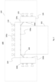
- FIG. 3 illustrates the radiating antenna 120 seen from above and with the deployable panels 104b, 104c in the deployed position.
- the two-phase loop 106 comprises channels shown in dotted lines allowing the fluid to circulate and recover the heat from each of the radiating elements 110 and the associated amplifier 103.
- the channels are arranged on the lower face of the radiating antenna 120 (i.e. on the face of the base 104 in contact with the chassis 102). It is also possible to arrange the channels on the opposite face of the base, face on which the radiating elements 110 and the amplifiers 103 are arranged. It is also possible to embed the channels in the base 104.
- the channels can run along the edges of the base 104 and advantageously opposite each of the radiating elements 110 and amplifiers 103 in order to best ensure temperature homogeneity over the entire surface of the base 104.
- the fluid circulates in the radiating antenna 120 between a fluid inlet 112 and a fluid outlet 114.
- the two-phase loop 106 of the present invention is configured so that, when the fluid circulates in the two-phase loop 106 close to the radiating elements 110 and recovers heat from the radiating elements 110, the temperature of the fluid increases until it reaches its saturation temperature.
- several solutions can be proposed such as the use of heaters, the regulation of the flow rate in the panels or the use of a heat exchanger between an inlet and an outlet of the panels.
- the two-phase loop therefore makes it possible to recover the heat emitted by the radiating elements and the amplifiers 103, even for a very large number of radiating elements (for example, thousands) with constant exchange conditions and, therefore, temperature homogeneity of the radiating elements (with a difference of less than 10°C between the radiating elements), which is necessary to guarantee the radiofrequency performance of the radiating antenna.
- the two-phase loop 106 may include a heat exchanger (not shown) between an outlet of the pump 114 and the inlet 112 in order to increase the temperature of the fluid to its saturation temperature before reaching the radiating elements 110.
- the two-phase loop 106 may include one or more temperature sensors for measuring the temperature of the fluid at one or more locations and thus verifying whether the temperature of the fluid is indeed above the saturation temperature at the radiating antenna 120. Similarly, one or more temperature sensors may ensure that the temperature of the fluid is below the saturation temperature before circulating in the pump (the pump operating with a fluid in the liquid state.
- the two-phase loop 106 comprises at least one condenser 116 configured to remove heat from the fluid.
- a condenser 116 is shown.
- two or more condensers may be used.
- the condenser 116 may be thermally linked to one or more radiators for removing heat from the radiating elements 110 and associated amplifiers recovered by the fluid to the outside of the satellite 100.
- the condenser 116 allows the heat transfer fluid to be condensed and then the temperature of the fluid to be reduced below its saturation temperature in order to return to the liquid state.
- the fluid may therefore be in the liquid state at an outlet of the condenser 116 in order to be in the liquid state while circulating in the pump 114.
- the radiating antenna 120 comprises two deployable panels 104b, 104c which are in the deployed position.
- the flexible connections 108 make it possible to connect the portion 106a of the two-phase loop 106 which is placed on the fixed panel 104a with the portion 106b of the two-phase loop 106 which is placed on the deployable panel 104b.
- the flexible connections 108 make it possible to connect the portion 106a of the two-phase loop 106 which is placed on the fixed panel 104a with the portion 106b of the two-phase loop 106 which is placed on the deployable panel 104c.
- the flexible connections 108 comprise channels configured to transmit signals carrying an electromagnetic wave emitted and/or received by the radiating elements 110.
- the flexible connections 108 in addition to transmitting the fluid through the two-phase loop 106, can transmit optical, electrical, etc. signals allowing the operation of the radiating antenna 120.
- the pump is used to circulate the fluid with a two-phase state in each panel 104a, 104b, 104c.
- other systems may be used to circulate the fluid with a two-phase state in each panel, such as a compressor.
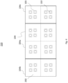
- FIG. 4 illustrates another example of a radiating antenna 220 seen from above and with the deployable panels 104b, 104c in the deployed position.
- the two-phase loop 106 is not shown.
- the two-phase loop 106 described above with regard to the Figure 3 can be used with the 220 radiating antenna.
- the antenna radiating antenna 220 comprises tiles 202 fixed on the base 104. Each tile 202 comprises radiating elements 110. Each tile 202 is connected to the adjacent tile(s) so as to form a radiating antenna 220 having the functionalities of a formed radiating antenna not being divided into different tiles.
- the tiles 202 make it possible to facilitate the manufacture and assembly of large radiating antennas.
- the radiating antenna 220 can have an area ranging from 8 m 2 to 20 m 2 .
- the manufacture and assembly of the radiating antenna 220 can be facilitated.
- the invention has been illustrated and described in detail using a preferred embodiment, the invention is not limited to the disclosed examples. Other variations may be deduced by those skilled in the art without departing from the scope of protection of the claimed invention.
- the radiating antenna 120, 220 may comprise several hundred to several thousand radiating elements 110.
- the invention has been illustrated with two deployable panels.
- the satellite may comprise only one deployable panel.
- an amplifier is associated with a radiating element.
- an amplifier may be associated with several radiating elements.
- the radiating and amplifier elements are mounted on the upper face of the panels and the two-phase loop is on the lower face of the panels.
- the radiating elements may be fixed on the upper face of the panels, the amplifiers placed on trays placed inside the panels, and whose planes are orthogonal to the upper and lower faces of the panels.
Landscapes
- Engineering & Computer Science (AREA)
- Remote Sensing (AREA)
- Aviation & Aerospace Engineering (AREA)
- General Physics & Mathematics (AREA)
- Astronomy & Astrophysics (AREA)
- Physics & Mathematics (AREA)
- Environmental & Geological Engineering (AREA)
- Environmental Sciences (AREA)
- General Health & Medical Sciences (AREA)
- Toxicology (AREA)
- Biodiversity & Conservation Biology (AREA)
- Life Sciences & Earth Sciences (AREA)
- Health & Medical Sciences (AREA)
- Details Of Aerials (AREA)
Claims (7)
- Satellit, umfassend:ein Gestell (102),eine Strahlungsantenne (120), umfassend:Strahlungselemente (110);Verstärker (103), die mit den Strahlungselementen verbunden sind;einen Sockel (104), auf dem die Strahlungselemente und die Verstärker montiert sind, wobei der Sockel dazu konfiguriert ist, die Strahlungselemente und die Verstärker zu tragen und Wärme, die von den Strahlungselementen und/oder den Verstärkern (103) emittiert wird, wenn diese im Betrieb sind, abzuführen, wobei der Sockel mindestens eine an dem Gestell befestigte ortsfeste Platte (104a) und mindestens eine ausfahrbare Platte (104b, 104c), die an der ersten Platte angelenkt ist, umfasst, wobei jede der Platten mindestens eines der Strahlungselemente und einen Verstärker trägt; undeinen Zweiphasenkreislauf (106), in dem ein Fluid zirkuliert und der dazu konfiguriert ist, die Wärme zurückzugewinnen und an den Sockel übertragen wird, wobei der Zweiphasenkreislauf umfasst:zwei Teile (106a, 106b, 106c), wobei jeder an einer der zwei Platten des Sockels befestigt ist; undflexible Verbindungen (108), die mindestens einen flexiblen Wärmekanal umfassen und die Teile des Zweiphasenkreislaufs verbinden, wobei das Fluid in dem mindestens einen flexiblen Wärmekanal zirkuliert.
- Satellit nach Anspruch 1, wobei die ausfahrbare Platte dazu konfiguriert ist, eine ausgefahrene Position, wenn der Satellit im Betrieb ist, und eine zurückgezogene Position, wenn der Satellit im Transport ist, aufzuweisen.
- Satellit nach einem der vorhergehenden Ansprüche, wobei der Zweiphasenkreislauf eine Pumpe, die dazu konfiguriert ist, das Fluid mit einem Durchfluss, der höher als ein vorbestimmter Wert ist, zirkulieren zu lassen, und einen Zweiphasenzustand in jeder Platte und mindestens einen Kondensator, der dazu konfiguriert ist, Wärme des Fluids abzuführen, umfasst.
- Satellit nach einem der vorhergehenden Ansprüche, wobei die Strahlungsantenne eine Oberfläche aufweist, die von 8 m2 bis 20 m2 reicht.
- Satellit nach einem der vorhergehenden Ansprüche, wobei das Fluid ein Kühlmittel ist, das zu einer Nutzung im flüssigen Zustand und im Zweiphasenzustand konfiguriert ist.
- Satellit nach Anspruch 5, wobei das Kühlmittel Ammoniak ist.
- Satellit nach einem der vorhergehenden Ansprüche, wobei die flexiblen Verbindungen Kanäle umfassen, die dazu konfiguriert sind, Signale zu übertragen, die eine elektromagnetische Welle tragen, die von den Strahlungselementen emittiert und/oder empfangen wird.
Applications Claiming Priority (1)
| Application Number | Priority Date | Filing Date | Title |
|---|---|---|---|
| FR2114413A FR3131283B1 (fr) | 2021-12-23 | 2021-12-23 | Satellite comprenant une antenne rayonnante deployable. |
Publications (3)
| Publication Number | Publication Date |
|---|---|
| EP4201819A1 EP4201819A1 (de) | 2023-06-28 |
| EP4201819B1 true EP4201819B1 (de) | 2025-04-23 |
| EP4201819C0 EP4201819C0 (de) | 2025-04-23 |
Family
ID=81749368
Family Applications (1)
| Application Number | Title | Priority Date | Filing Date |
|---|---|---|---|
| EP22215632.5A Active EP4201819B1 (de) | 2021-12-23 | 2022-12-21 | Satellit mit ausfahrbarer antenne |
Country Status (3)
| Country | Link |
|---|---|
| EP (1) | EP4201819B1 (de) |
| ES (1) | ES3026860T3 (de) |
| FR (1) | FR3131283B1 (de) |
Family Cites Families (5)
| Publication number | Priority date | Publication date | Assignee | Title |
|---|---|---|---|---|
| US6003817A (en) * | 1996-11-12 | 1999-12-21 | Motorola, Inc. | Actively controlled thermal panel and method therefor |
| FR2840394B1 (fr) * | 2002-05-30 | 2004-08-27 | Cit Alcatel | Dispositif de transfert de chaleur pour satellite comprenant un evaporateur |
| US7551136B1 (en) * | 2006-07-24 | 2009-06-23 | The Boeing Company | Multi-beam phased array antenna for limited scan applications |
| AU2020276300B2 (en) * | 2019-05-15 | 2025-12-18 | Ast & Science, Llc | Solar, electronic, RF radiator for a self-contained structure for space application array |
| US11828536B2 (en) * | 2020-04-08 | 2023-11-28 | Lockheed Martin Corporation | Heat transfer assemblies with compliant heat pipes |
-
2021
- 2021-12-23 FR FR2114413A patent/FR3131283B1/fr active Active
-
2022
- 2022-12-21 ES ES22215632T patent/ES3026860T3/es active Active
- 2022-12-21 EP EP22215632.5A patent/EP4201819B1/de active Active
Also Published As
| Publication number | Publication date |
|---|---|
| ES3026860T3 (en) | 2025-06-12 |
| EP4201819A1 (de) | 2023-06-28 |
| FR3131283A1 (fr) | 2023-06-30 |
| FR3131283B1 (fr) | 2024-02-23 |
| EP4201819C0 (de) | 2025-04-23 |
Similar Documents
| Publication | Publication Date | Title |
|---|---|---|
| EP2226248B1 (de) | Wärmekontrollvorrichtung für ein Raumfahrzeug | |
| EP1366990B1 (de) | Wärmetauschvorrichtung mit Verdampfer für Satellit | |
| EP1961659B1 (de) | Vorrichtung zur Wärmeregelung an Bord eines Raumfahrzeuges | |
| EP2069201B1 (de) | Vorrichtung zur steuerung des wärmeflusses in einem raumfahrzeug und mit derartiger vorrichtung ausgestattetes raumfahrzeug | |
| US7513462B1 (en) | Satellite equipment mounting panel | |
| EP1468911A1 (de) | Satellit einschliesslich Mittel zum Wärmetransport von einem Vorrichtungsgestell zu Radiatorpaneelen | |
| EP3089912B1 (de) | Telekommunikationssatellitenarchitektur | |
| EP3672873B1 (de) | Raumfahrzeug, startgerät und stapel von raumfahrzeugen | |
| EP2500275A2 (de) | Strukturplatte eines Satelliten mit integrierten Wärmetauschern | |
| FR3072844A1 (fr) | Unite de liaison pour appareils a haute frequence | |
| EP2962390B1 (de) | Signalverstärkungssystem | |
| EP4201819A1 (de) | Satellit mit ausfahrbarer strahlungsquelle | |
| EP3259188B1 (de) | Künstlicher satellit | |
| WO2011120995A1 (fr) | Dispositif de controle thermique d'un tube a collecteur rayonnant comportant un ecran, une boucle fluide et un radiateur à haute temperature | |
| FR2811963A1 (fr) | Dispositif de dissipation de chaleur d'engin spatial utilisant des conduits de chaleur contenant un fluide agissant a une temperature moyenne | |
| EP4206601B1 (de) | Wärmetauschervorrichtung und ausrüstung mit der wärmetauschervorrichtung | |
| FR2759345A1 (fr) | Satellite geostationnaire stabilise trois axes a controle thermique perfectionne | |
| WO2003106264A1 (fr) | Dispositif de refroidissement pour vehicule spatial | |
| FR2850453A1 (fr) | Caloduc de tranfert de chaleur et/ou d'homogeneisation de temperatures sur un vehicule spatial | |
| FR2751473A1 (fr) | Structure d'antenne a modules actifs | |
| FR2815935A1 (fr) | Systeme de tubes thermiques a double alesage en une couche destine a des panneaux d'equipements et de radiateurs | |
| WO2021130457A1 (fr) | Structure porteuse pour véhicule spatial et procédé de montage d'une structure porteuse pour véhicule spatial | |
| EP4456127A1 (de) | Zylindrischer koaxialer kombinator |
Legal Events
| Date | Code | Title | Description |
|---|---|---|---|
| PUAI | Public reference made under article 153(3) epc to a published international application that has entered the european phase |
Free format text: ORIGINAL CODE: 0009012 |
|
| STAA | Information on the status of an ep patent application or granted ep patent |
Free format text: STATUS: THE APPLICATION HAS BEEN PUBLISHED |
|
| AK | Designated contracting states |
Kind code of ref document: A1 Designated state(s): AL AT BE BG CH CY CZ DE DK EE ES FI FR GB GR HR HU IE IS IT LI LT LU LV MC ME MK MT NL NO PL PT RO RS SE SI SK SM TR |
|
| STAA | Information on the status of an ep patent application or granted ep patent |
Free format text: STATUS: REQUEST FOR EXAMINATION WAS MADE |
|
| 17P | Request for examination filed |
Effective date: 20231129 |
|
| RBV | Designated contracting states (corrected) |
Designated state(s): AL AT BE BG CH CY CZ DE DK EE ES FI FR GB GR HR HU IE IS IT LI LT LU LV MC ME MK MT NL NO PL PT RO RS SE SI SK SM TR |
|
| GRAP | Despatch of communication of intention to grant a patent |
Free format text: ORIGINAL CODE: EPIDOSNIGR1 |
|
| STAA | Information on the status of an ep patent application or granted ep patent |
Free format text: STATUS: GRANT OF PATENT IS INTENDED |
|
| INTG | Intention to grant announced |
Effective date: 20241216 |
|
| GRAS | Grant fee paid |
Free format text: ORIGINAL CODE: EPIDOSNIGR3 |
|
| GRAA | (expected) grant |
Free format text: ORIGINAL CODE: 0009210 |
|
| STAA | Information on the status of an ep patent application or granted ep patent |
Free format text: STATUS: THE PATENT HAS BEEN GRANTED |
|
| AK | Designated contracting states |
Kind code of ref document: B1 Designated state(s): AL AT BE BG CH CY CZ DE DK EE ES FI FR GB GR HR HU IE IS IT LI LT LU LV MC ME MK MT NL NO PL PT RO RS SE SI SK SM TR |
|
| RAP3 | Party data changed (applicant data changed or rights of an application transferred) |
Owner name: THALES |
|
| REG | Reference to a national code |
Ref country code: GB Ref legal event code: FG4D Free format text: NOT ENGLISH |
|
| REG | Reference to a national code |
Ref country code: CH Ref legal event code: EP |
|
| REG | Reference to a national code |
Ref country code: DE Ref legal event code: R096 Ref document number: 602022013510 Country of ref document: DE |
|
| REG | Reference to a national code |
Ref country code: IE Ref legal event code: FG4D Free format text: LANGUAGE OF EP DOCUMENT: FRENCH |
|
| REG | Reference to a national code |
Ref country code: ES Ref legal event code: FG2A Ref document number: 3026860 Country of ref document: ES Kind code of ref document: T3 Effective date: 20250612 |
|
| U01 | Request for unitary effect filed |
Effective date: 20250513 |
|
| U07 | Unitary effect registered |
Designated state(s): AT BE BG DE DK EE FI FR IT LT LU LV MT NL PT RO SE SI Effective date: 20250519 |
|
| PG25 | Lapsed in a contracting state [announced via postgrant information from national office to epo] |
Ref country code: GR Free format text: LAPSE BECAUSE OF FAILURE TO SUBMIT A TRANSLATION OF THE DESCRIPTION OR TO PAY THE FEE WITHIN THE PRESCRIBED TIME-LIMIT Effective date: 20250724 Ref country code: NO Free format text: LAPSE BECAUSE OF FAILURE TO SUBMIT A TRANSLATION OF THE DESCRIPTION OR TO PAY THE FEE WITHIN THE PRESCRIBED TIME-LIMIT Effective date: 20250723 |
|
| PG25 | Lapsed in a contracting state [announced via postgrant information from national office to epo] |
Ref country code: PL Free format text: LAPSE BECAUSE OF FAILURE TO SUBMIT A TRANSLATION OF THE DESCRIPTION OR TO PAY THE FEE WITHIN THE PRESCRIBED TIME-LIMIT Effective date: 20250423 |
|
| PG25 | Lapsed in a contracting state [announced via postgrant information from national office to epo] |
Ref country code: HR Free format text: LAPSE BECAUSE OF FAILURE TO SUBMIT A TRANSLATION OF THE DESCRIPTION OR TO PAY THE FEE WITHIN THE PRESCRIBED TIME-LIMIT Effective date: 20250423 |
|
| PG25 | Lapsed in a contracting state [announced via postgrant information from national office to epo] |
Ref country code: RS Free format text: LAPSE BECAUSE OF FAILURE TO SUBMIT A TRANSLATION OF THE DESCRIPTION OR TO PAY THE FEE WITHIN THE PRESCRIBED TIME-LIMIT Effective date: 20250723 |
|
| PG25 | Lapsed in a contracting state [announced via postgrant information from national office to epo] |
Ref country code: IS Free format text: LAPSE BECAUSE OF FAILURE TO SUBMIT A TRANSLATION OF THE DESCRIPTION OR TO PAY THE FEE WITHIN THE PRESCRIBED TIME-LIMIT Effective date: 20250823 |
|
| U20 | Renewal fee for the european patent with unitary effect paid |
Year of fee payment: 4 Effective date: 20251118 |
|
| PG25 | Lapsed in a contracting state [announced via postgrant information from national office to epo] |
Ref country code: SM Free format text: LAPSE BECAUSE OF FAILURE TO SUBMIT A TRANSLATION OF THE DESCRIPTION OR TO PAY THE FEE WITHIN THE PRESCRIBED TIME-LIMIT Effective date: 20250423 |
|
| PG25 | Lapsed in a contracting state [announced via postgrant information from national office to epo] |
Ref country code: CZ Free format text: LAPSE BECAUSE OF FAILURE TO SUBMIT A TRANSLATION OF THE DESCRIPTION OR TO PAY THE FEE WITHIN THE PRESCRIBED TIME-LIMIT Effective date: 20250423 |
|
| PG25 | Lapsed in a contracting state [announced via postgrant information from national office to epo] |
Ref country code: SK Free format text: LAPSE BECAUSE OF FAILURE TO SUBMIT A TRANSLATION OF THE DESCRIPTION OR TO PAY THE FEE WITHIN THE PRESCRIBED TIME-LIMIT Effective date: 20250423 |
|
| PLBE | No opposition filed within time limit |
Free format text: ORIGINAL CODE: 0009261 |
|
| STAA | Information on the status of an ep patent application or granted ep patent |
Free format text: STATUS: NO OPPOSITION FILED WITHIN TIME LIMIT |
|
| REG | Reference to a national code |
Ref country code: CH Ref legal event code: L10 Free format text: ST27 STATUS EVENT CODE: U-0-0-L10-L00 (AS PROVIDED BY THE NATIONAL OFFICE) Effective date: 20260304 |
|
| 26N | No opposition filed |
Effective date: 20260126 |
|
| PGFP | Annual fee paid to national office [announced via postgrant information from national office to epo] |
Ref country code: ES Payment date: 20260114 Year of fee payment: 4 |
|
| PG25 | Lapsed in a contracting state [announced via postgrant information from national office to epo] |
Ref country code: MC Free format text: LAPSE BECAUSE OF FAILURE TO SUBMIT A TRANSLATION OF THE DESCRIPTION OR TO PAY THE FEE WITHIN THE PRESCRIBED TIME-LIMIT Effective date: 20250423 |
|
| REG | Reference to a national code |
Ref country code: CH Ref legal event code: H13 Free format text: ST27 STATUS EVENT CODE: U-0-0-H10-H13 (AS PROVIDED BY THE NATIONAL OFFICE) Effective date: 20260723 |