EP4201831A1 - Unité de serrage et unité de stockage dotée d'au moins une unité de serrage - Google Patents
Unité de serrage et unité de stockage dotée d'au moins une unité de serrage Download PDFInfo
- Publication number
- EP4201831A1 EP4201831A1 EP22214894.2A EP22214894A EP4201831A1 EP 4201831 A1 EP4201831 A1 EP 4201831A1 EP 22214894 A EP22214894 A EP 22214894A EP 4201831 A1 EP4201831 A1 EP 4201831A1
- Authority
- EP
- European Patent Office
- Prior art keywords
- locking
- anchor
- section
- tensioning
- clamping unit
- Prior art date
- Legal status (The legal status is an assumption and is not a legal conclusion. Google has not performed a legal analysis and makes no representation as to the accuracy of the status listed.)
- Granted
Links
Images



Classifications
-
- B—PERFORMING OPERATIONS; TRANSPORTING
- B65—CONVEYING; PACKING; STORING; HANDLING THIN OR FILAMENTARY MATERIAL
- B65D—CONTAINERS FOR STORAGE OR TRANSPORT OF ARTICLES OR MATERIALS, e.g. BAGS, BARRELS, BOTTLES, BOXES, CANS, CARTONS, CRATES, DRUMS, JARS, TANKS, HOPPERS, FORWARDING CONTAINERS; ACCESSORIES, CLOSURES, OR FITTINGS THEREFOR; PACKAGING ELEMENTS; PACKAGES
- B65D5/00—Rigid or semi-rigid containers of polygonal cross-section, e.g. boxes, cartons or trays, formed by folding or erecting one or more blanks made of paper
- B65D5/42—Details of containers or of foldable or erectable container blanks
- B65D5/44—Integral, inserted or attached portions forming internal or external fittings
- B65D5/441—Reinforcements
- B65D5/445—Reinforcements formed separately from the container
-
- F—MECHANICAL ENGINEERING; LIGHTING; HEATING; WEAPONS; BLASTING
- F16—ENGINEERING ELEMENTS AND UNITS; GENERAL MEASURES FOR PRODUCING AND MAINTAINING EFFECTIVE FUNCTIONING OF MACHINES OR INSTALLATIONS; THERMAL INSULATION IN GENERAL
- F16B—DEVICES FOR FASTENING OR SECURING CONSTRUCTIONAL ELEMENTS OR MACHINE PARTS TOGETHER, e.g. NAILS, BOLTS, CIRCLIPS, CLAMPS, CLIPS OR WEDGES; JOINTS OR JOINTING
- F16B19/00—Bolts without screw-thread; Pins, including deformable elements; Rivets
- F16B19/02—Bolts or sleeves for positioning of machine parts, e.g. notched taper pins, fitting pins, sleeves, eccentric positioning rings
-
- F—MECHANICAL ENGINEERING; LIGHTING; HEATING; WEAPONS; BLASTING
- F16—ENGINEERING ELEMENTS AND UNITS; GENERAL MEASURES FOR PRODUCING AND MAINTAINING EFFECTIVE FUNCTIONING OF MACHINES OR INSTALLATIONS; THERMAL INSULATION IN GENERAL
- F16B—DEVICES FOR FASTENING OR SECURING CONSTRUCTIONAL ELEMENTS OR MACHINE PARTS TOGETHER, e.g. NAILS, BOLTS, CIRCLIPS, CLAMPS, CLIPS OR WEDGES; JOINTS OR JOINTING
- F16B2/00—Friction-grip releasable fastenings
- F16B2/02—Clamps, i.e. with gripping action effected by positive means other than the inherent resistance to deformation of the material of the fastening
- F16B2/06—Clamps, i.e. with gripping action effected by positive means other than the inherent resistance to deformation of the material of the fastening external, i.e. with contracting action
- F16B2/12—Clamps, i.e. with gripping action effected by positive means other than the inherent resistance to deformation of the material of the fastening external, i.e. with contracting action using sliding jaws
-
- F—MECHANICAL ENGINEERING; LIGHTING; HEATING; WEAPONS; BLASTING
- F16—ENGINEERING ELEMENTS AND UNITS; GENERAL MEASURES FOR PRODUCING AND MAINTAINING EFFECTIVE FUNCTIONING OF MACHINES OR INSTALLATIONS; THERMAL INSULATION IN GENERAL
- F16B—DEVICES FOR FASTENING OR SECURING CONSTRUCTIONAL ELEMENTS OR MACHINE PARTS TOGETHER, e.g. NAILS, BOLTS, CIRCLIPS, CLAMPS, CLIPS OR WEDGES; JOINTS OR JOINTING
- F16B21/00—Means for preventing relative axial movement of a pin, spigot, shaft or the like and a member surrounding it; Stud-and-socket releasable fastenings
- F16B21/06—Releasable fastening devices with snap-action
- F16B21/07—Releasable fastening devices with snap-action in which the socket has a resilient part
- F16B21/073—Releasable fastening devices with snap-action in which the socket has a resilient part the socket having a resilient part on its inside
-
- F—MECHANICAL ENGINEERING; LIGHTING; HEATING; WEAPONS; BLASTING
- F16—ENGINEERING ELEMENTS AND UNITS; GENERAL MEASURES FOR PRODUCING AND MAINTAINING EFFECTIVE FUNCTIONING OF MACHINES OR INSTALLATIONS; THERMAL INSULATION IN GENERAL
- F16B—DEVICES FOR FASTENING OR SECURING CONSTRUCTIONAL ELEMENTS OR MACHINE PARTS TOGETHER, e.g. NAILS, BOLTS, CIRCLIPS, CLAMPS, CLIPS OR WEDGES; JOINTS OR JOINTING
- F16B21/00—Means for preventing relative axial movement of a pin, spigot, shaft or the like and a member surrounding it; Stud-and-socket releasable fastenings
- F16B21/09—Releasable fastening devices with a stud engaging a keyhole slot
Definitions
- the present invention relates to a tensioning unit for tensioning a first and an opposite second side wall of a storage unit, in particular a carton, in a tensioned state. Furthermore, the present invention relates to a storage unit for receiving bulk material with at least one clamping unit according to the invention.
- the known storage unit forms a space for accommodating the bulk material between a total of four side walls lying opposite one another in pairs. Two opposing side walls are clamped together by a clamping unit in such a way that the weight acting on the side walls is reduced. Due to the reduced force acting on the side walls, the side walls can be made thinner, which is why on the one hand the production costs of the storage unit can be reduced due to the material saving and the transport costs of the bulk material using the storage unit can be reduced due to the larger bulk material volume.
- the tensioning unit which is designed as a separate component from the storage unit, includes a tensioning strand that extends between a first tensioning anchor and a free end.
- the tension cord includes a locking area with a large number of adjacent latching steps.
- the known tension cord includes a second tensioning anchor, which is formed by a separate component and includes locking means, which are designed to be releasably fixed in one of the latching steps. In a stressed state, two opposite side walls can thus be braced by the tendon cord, with one of the two stressing anchors Force input surface is formed, each abutting the outside of one of the side walls of the storage unit.
- the second tensioning anchor comprises a slot-like recess for forming a guide for fixing the tensioning anchor, which opens into the locking means.
- a tensioning unit including a tensioning cord is known to the applicant, in which the tensioning cord has a plurality of locking sections and thus allows adaptation to transport and storage units with different dimensions.
- a connecting device for a construction system and a construction system for furniture is also known, in which a pull rod is fastened or screwed on both sides in order to press components against one another.
- one of the second tensioning anchors on the outside which are designed to be detachable from the tensioning cord, can be subjected to a force during loading or unloading, for example by a side edge of an adjacent storage unit or the tensioning anchor of the adjacent storage unit in the area of the slot or the slot-like recess. If this force acts on the second tensioning anchor in the direction of the guide, in the worst case this can result in the second tensioning anchor coming loose from the latching step, which then occurs due to the weight of the tensioning anchor acting on the side walls Bulk material immediately leads to a collision of the storage unit. This leads to complex clean-up work and causes a considerable loss of time.
- the present invention is therefore based on the object of overcoming the disadvantages known from the prior art.
- the object of the present invention is to specify a tensioning unit and a storage unit in which accidental release of the second anchor unit from the tendon cord can occur only significantly less frequently or much less likely, even when several storage units are arranged directly adjacent to one another.
- the task is solved by the clamping unit with the features of claim 1. Furthermore, the object is achieved by a storage unit with at least one clamping unit according to the invention.
- a tensioning unit for tensioning opposing side walls, in particular a first and an opposing second side wall, of a storage unit, in particular a carton, in a tensioned state.
- the tensioning unit comprises a tensioning cord which comprises a first tensioning anchor, extends from the first tensioning anchor along a longitudinal direction to a free end and between the first tensioning anchor and the free end comprises at least one locking region with a large number of locking steps arranged adjacent to one another in the longitudinal direction, with the first tensioning anchor forming a first force application surface for the first side wall in the tensioned state for supporting one of the side walls, in particular the first side wall, on the outside.
- a tensioning cord which comprises a first tensioning anchor, extends from the first tensioning anchor along a longitudinal direction to a free end and between the first tensioning anchor and the free end comprises at least one locking region with a large number of locking steps arranged adjacent to one another in the longitudinal direction, with the first tensioning anchor forming a first force application surface for the first side wall in the tensioned state for supporting one of the side walls, in particular the first side wall, on the outside.
- the tensioning unit comprises a second tensioning anchor, which can be connected to the tensioning strand, for supporting one of the other side walls, in particular the opposite second side wall, by forming a further force application surface, with the second tensioning anchor comprising locking means which are designed to interact with the locking area in such a way that the second tensioning anchor can be fixed in one of the locking stages.
- the second stressing anchor has an outer section with an outer contour that is completely closed in the circumferential direction and an inner section with an entry opening for leading through and/or inserting the free end of the tendon cord and for guiding and/or positioning the locking area formed by the tendon cord in the clamping state included.
- the second stressing anchor is designed as a separate component from the stressing strand and in particular also from the first stressing anchor.
- the second stressing anchor can be connected to the tendon to realize the stressed state.
- the second tensioning anchor comprises the locking means, which are designed in such a way that the second tensioning anchor can be fixed in one of the locking stages.
- the locking steps which are comprised by the tension cord, are adjacent to one another with respect to the longitudinal extent of the tension cord Locking area formed.
- the section that extends between the first tensioning anchor and the second tensioning anchor can thus advantageously be adjusted in steps, which is why the tensioning unit according to the invention can be adapted to storage units of different widths and/or lengths.
- the first force application surface, which is formed by the first tensioning anchor, and the further force application surface, which is formed by the second tensioning anchor make optimal, preferably uniform, contact.
- the outer section is understood to mean a region of the second tensioning anchor that forms the outer contour of the second tensioning anchor.
- the outer contour represents a frame element or a housing element that is completely closed, in particular with respect to a circumferential direction. In the tensioned state, the circumferential direction runs around the tension cord, which extends along the longitudinal direction.
- the outer section is arranged on the outside or radially on the outside around the inner section and completely encloses it in the circumferential direction.
- the outer section forms an outer contour for the inner section, which completely encloses, preferably frames, the inner section.
- the inner section is surrounded and/or framed by the outer section in the circumferential direction. Furthermore, the inner section includes the entry opening, which is designed for inserting the free end and thus the tendon cord and which arranges or aligns the locking area relative to the locking means in such a way that the locking means can be fixed in one of the locking stages in order to to be connected to the second stressing anchor.
- the tendon strand To fix the second stressing anchor in one of the locking stages, the tendon strand must be inserted into the entry opening starting from the free end and then carried out and/or pushed through the entry opening until the locking means are fixed in a suitable locking stage and the second stressing anchor on the side wall of the storage unit, in particular on the outside of the second side wall, in order to form the additional force application surface for the second side wall through the second tensioning anchor.
- the inlet opening is preferably designed as a material cutout or material recess in the inner section.
- the locking means come into operative contact with the locking area and thus with the locking cord, preferably circumferentially, more preferably on two or four opposite sides of the locking cord, which is why the locking steps in the locking cord are preferably formed along the entire circumferential direction.
- the design of the second tensioning anchor according to the invention leads to improved fixing of the second tensioning anchor in one of the locking stages in the tensioned state. Due to the fact that the tendon strand is completely surrounded by the second stressing anchor, in particular by the outer section, the accidental release of the second stressing anchor, in particular the lateral pushing out of the second stressing anchor, as is possible in the generic prior art, during loading and unloading despite a Lateral application of force to the second anchor unit is largely prevented. The omission of the slit-like recess in particular reduces the possibilities of attack that can lead to an unintentional loosening of the stressing anchor.
- the handling of the clamping unit according to the invention and/or the handling of a storage unit with the clamping unit according to the invention is thus simplified, in particular when loading and unloading a loading space of a truck with a large number of storage units that are arranged and/or stacked directly adjacent to one another, since it is no longer necessary to accidental release of the second stressing anchor from the locking area.
- the tensioning unit in particular the tensioning cord
- the tensioning unit is designed as a disposable product and is in particular not used again after use.
- the advantage is that the unintentional loosening of the stressing anchor is completely prevented.
- a stressing anchor can be used, which greatly reduces the risk of unintentional loosening due to the outer section according to the invention, which is closed in the circumferential direction and thereby avoids the known slot-like recess, although it does not make it impossible but at the same time can be separated non-destructively from the tendon cord and reused.
- a first embodiment of the tensioning anchor is described below, which does not provide for non-destructive releasing of the tensioning anchor.
- the locking means comprise an edge section that completely frames and/or delimits the entry opening, the edge section being designed in such a way that it can be fixed in one of the locking stages of the locking area.
- the edge section is preferably formed by an area of the inner section which surrounds the inlet opening in the circumferential direction, preferably delimiting it directly, more preferably forming it within the second tensioning anchor and/or the inner section.
- the edge section which extends around the circumference of the inlet opening in a depth and/or radial direction in the direction of the outer section, varies with respect to the depth and/or radial direction and/or has different widths and/or thicknesses.
- the edge section can, for example, have a round or oval or spiked or star-shaped configuration and thus comprise a round, oval, spiked or star-shaped inlet opening, ie an inlet opening with a round or oval or spiked or star-shaped inner contour.
- the plurality of locking steps or latching steps have a sawtooth-shaped contour in longitudinal section with obliquely aligned sliding surfaces and vertically aligned end faces in order to realize the fixing of the second stressing anchor in such a way that when the second stressing anchor is inserted it initially becomes a elastic deformation of the edge portion when sliding along over the various sliding surfaces, the edge portion then being substantially parallel to the The end face is aligned and at least partially rests against it in order to prevent the second anchor bolt from being guided out counter to the direction of insertion.
- the edge section comprises at least three, preferably at least four, latching lugs, which are in particular designed in the shape of a piece of cake and which protrude into the inlet opening in some areas in such a way that the at least three, preferably at least four, latching lugs can be brought into engagement with one of the locking stages at the end.
- the latching lugs are preferably designed in such a way that they interact with the locking steps at the ends to fix the second tensioning anchor in the locking area. Furthermore, the latching lugs are preferably arranged opposite one another and/or spaced apart from one another in the circumferential direction and/or evenly distributed and in particular designed in such a way that the latching lugs deform elastically when the second tensioning anchor is inserted into one of the locking stages, in particular when sliding over the sliding surfaces.
- the at least three latching lugs are delimited in the circumferential direction by at least three slit-shaped material cutouts, or that the at least four detent lugs are delimited in the circumferential direction by at least four slit-shaped material cutouts.
- the edge section comprises at least three, preferably at least four, slit-shaped material recesses, which are arranged in particular in the circumferential direction between two adjacent latching lugs.
- the slit-shaped material recesses are preferably formed in the inner section, can preferably also extend in certain areas in the outer section.
- the slit-shaped material cutouts which limit the detents in the circumferential direction, lead to improved elastic deformation of the detents.
- the locking means in particular the inner section, are arranged in a depression and/or depression formed by the second clamping anchor, in particular the outer section, such that in the clamped state at least one of the locking stages is in the depression and / or sink can be arranged.
- the indentation and/or sink advantageously makes it possible for an end piece of the clamping cord, which extends in the longitudinal direction behind the locking stage in which the locking means are fixed, to be prevented from protruding.
- the tensioning cord is advantageously shortened by a side cutter in such a way that the area projecting beyond the locking means in the longitudinal direction, in particular the end piece, of the tensioning cord is completely accommodated in the depression.
- the entry opening for inserting the free end and for guiding and/or positioning the locking area in the clamped state has two sections, a first section with a larger cross section enabling the insertion of the free end and a second Section with a smaller cross-section allows positioning or fastening of the locking area in the clamped state.
- the larger cross-section is, to some extent a matter of course, designed in such a way that it turns out to be larger than the maximum diameter of the stressing anchor.
- the smaller cross section of the second section of the entry opening is designed in such a way that clamping or latching with the locking area, in particular with locking steps of the locking area, is made possible and thus the creation and maintenance of a clamped state is achieved.
- the function or operation of the stressing anchor is basically such that the free end of the stressing strand is first inserted through the first section of the entry opening and the stressing strand is tensioned or tightened and in the tightened state the stressing anchor is thus displaced relative to or in relation to the tendon is moved so that, preferably without reducing or eliminating the prestress, the tension cord, in particular the locking area, is transferred into the second section of the entry opening and causes latching or jamming there.
- This relative movement can preferably be carried out reversibly or vice versa, so that the clamping state can be released can be achieved non-destructively by displacing or moving the stressing anchor in relation to the stressing strand, in particular the locking area, so that the latter returns from the second section of the entry opening into the first section of the entry opening, in which the tension is then released and the stressing anchor is loosened or removed can be.
- the first section and the second section of the inlet opening are connected to one another via a constriction.
- the constriction thus represents a resistance that has to be overcome when transferring the tendon cord from the first section to the second section and vice versa.
- the constriction and overcoming it with the tension cord leads to the establishment of the tensioned state and to the release of the tensioned state.
- the second section of the inlet opening has a widening cross section in the longitudinal direction, preferably in the shape of a truncated cone, in particular with a widening angle that essentially corresponds to an angle between adjacent locking steps of the locking area.
- the constriction is designed to be elastically deformable on one side or on both sides.
- the terms one-sided and two-sided should not be confused or equated with the terms "in one direction" or "in both directions”.
- the transition between the first section and the second section of the inlet opening is achieved along the contour of the inlet opening by two sections of the contour that are essentially opposite one another.
- a one-sided deformability of the constriction should therefore be understood in such a way that one of these sections of the contour is deformable.
- deformability on both sides should be understood in such a way that both, preferably opposite, sections of the contour of the inlet opening, which form or delimit the constriction, have elastic deformability.
- the deformability serves to ensure that the tendon cord can be transferred from the first section of the entry opening to the second section of the entry opening with relatively small forces, preferably with temporary deformation, in particular widening, and after passing the constriction, nevertheless, the best possible and secure latching or attachment of the stressing anchor to the stressing strand is achieved in particular by the elastically deformable constriction being returned or deformed partially or completely to its original shape.
- the deformability of the constriction by material recesses in the radial is effected on the outside of the constriction located areas of the inner section of the stressing anchor.
- the elastic deformability of the constriction can be produced and also adjusted in a particularly simple manner by means of corresponding material recesses. Because the further away the material cutouts are from the constriction, the stiffer the elastic deformability of the constriction will be.
- Such material recesses can be implemented easily and inexpensively at the same time, for example as part of an injection molding production process for producing the second tensioning anchor, without any particular challenges.
- the material recesses are arranged in such a way that the constriction is delimited by material webs acting as springs.
- the outer section has a projection, preferably on an outer edge, which is arranged essentially in the extension of a center point of the first section of the inlet opening and a center point of the second section of the inlet opening.
- the projection can be used with appropriate tools or to effect the movement or displacement of the stressing anchor, essentially at right angles to the longitudinal axis of the tendon, by means of a relative movement in relation to the stressing anchor and thereby to transfer the tendon from the first section of the inlet opening to the second section of the inlet opening, or vice versa.
- the locking steps in the tensioning cord are formed on at least two opposite outer sides of the tensioning cord.
- the large number of locking steps or latching steps which preferably have a sawtooth-shaped contour in longitudinal section with obliquely aligned sliding surfaces and vertically aligned end faces, are preferably formed on two opposite outer sides of the tension cord and thus also interact with at least two latching lugs.
- the locking means and the locking area are thus advantageously designed to be robust, in order to prevent the second tensioning anchor from being released from one of the locking stages in which it was previously fixed, even in the case of high forces.
- the tension cord has a round or an oval cross-sectional area, with it being further developed in this connection that the locking steps are designed to be continuous, particularly flat and/or uniform, on the circumference of the tension cord.
- the end section of the tension cord forms a point at the free end in order to enable a side wall to be pierced.
- a tool-free assembly of the clamping unit is thus advantageously achieved.
- the tension cord for forming the locking steps comprises a succession and/or series and/or chain of truncated cone sections each comprising an annular end face, which are designed in such a way that the locking means, in particular the edge section or the locking lugs, engage can be brought with one of the annular face of one of the truncated cone sections.
- the ring-shaped end faces which are formed by the round tension cord in the radial direction, thus each connect two lateral faces of two adjacent truncated cone sections.
- the free end of the stressing cord is inserted into the entry opening, with the elastically deformable edge section and/or the elastically deformable locking lugs sliding over the sloping lateral surface when the second stressing anchor is displaced relative to the stressing cord.
- first tensioning anchor and/or the second tensioning anchor is designed in the shape of a plate and comprises at least one stiffening element designed in the radial direction, which is designed in particular in the form of a bar or web.
- the stiffening element formed in the inner section and/or outer section in the radial direction leads to improved dimensional stability of the second tensioning anchor.
- the stiffening elements lead to an advantageous reduction in material, which is why the clamping unit can be produced more cost-effectively.
- first stressing anchor and the stressing strand are monolithic and/or integral with one another and/or are integrally formed and in particular by means of injection molding technology from one piece, in particular an injection molding, can be produced or are produced.
- the monolithic production of the first stressing anchor together with the stressing strand leads to a cost-effective way of manufacturing the stressing unit. Furthermore, a maximum tensile force acting on the first stressing anchor in the stressed state can be maximized by the monolithic connection between the first stressing anchor and stressing strand. For large quantities, low production costs for the clamping unit can be achieved thanks to the injection molding technique.
- the tensioning cord comprises at least two locking regions which extend in different sections with respect to the longitudinal extent of the tensioning cord. At least one connecting section is preferably arranged between a first locking area and a second locking area, which connects the first locking area from the second locking area in the longitudinal direction.
- the connecting section does not include any locking steps and preferably differs in its surface finish from the at least two locking areas.
- a tensioning unit In connection with rectangular storage units, a tensioning unit can thus be used for tensioning over the width extension by means of the first locking area and for tensioning over the length extension by means of the second locking area.
- tension cord is designed in the longitudinal direction in such a way that the first locking region can interact with opposite, spaced side walls of a storage unit in the range of essentially 600 mm, in particular between 540 mm and 630 mm, and that the at least one second locking area is designed to interact with opposite, spaced side walls of a storage unit in the range of essentially 800 mm, in particular between 740 mm and 830 mm.
- the tendon cord comprises a third locking area, the third locking area being designed to interact with opposite side walls of a storage unit in the area of essentially 1200 mm, in particular between 1140 mm and 1230 mm starting from the first tensioning anchor.
- the first locking area and the third locking area are reversed.
- the first locking area is designed to interact with opposite side walls of a storage unit in the area of essentially 1200 mm and then extends, in particular starting from the first tensioning anchor, in an area of 1140 mm to 1230 mm.
- the third locking area is in particular formed in an area of essentially 600 mm and then extends, in particular starting from the first tensioning anchor, in an area of 540 mm to 630 mm.
- a storage unit in particular a carton, with opposite side walls, in particular carton walls, which delimit a receiving space for bulk material, in particular plastic granulate, on the jacket side and at least one according to the invention Include clamping unit for clamping two opposite side walls.
- the Fig. 1a shows a clamping unit 1 according to the invention with a fixed second clamping anchor 7 according to a first preferred embodiment in a perspective view.
- the clamping unit 1 according to the invention comprises a tendon cord 2, which extends along a longitudinal direction L from a first stressing anchor 3 to a free end 4 formed by the tendon cord 2, which is in the Figure 2a is shown extends.
- the stressing strand 2 comprises at least one locking region 5 with a plurality of locking steps 61, 62, 63 adjacent to one another in the longitudinal direction L Figure 2a are shown and are designed to interact with locking means 9 of the second stressing anchor 7 in such a way that the second stressing anchor 7, which is designed as a separate and thus connectable component to the stressing cord 2 having the first stressing anchor 3, can be fixed in one of the locking stages 61-63.
- the second stressing anchor 7 comprises an outer section 10 with an outer contour 11 which is completely closed in the circumferential direction and has an inner section 12 with an inlet opening 13 .
- the entry opening 13 is designed for inserting the free end 4 of the tensioning cord 2 and guides and/or positions the locking region 5 of the tensioning cord 2 in a tensioning state of the tensioning unit 1 according to the invention, which will be described in more detail later.
- the first tensioning anchor 3 is plate-shaped and extends radially to the round tensioning cord 2 in order to have a first force application surface 6 for a first or third side wall 101, 103 in the tensioned state 4 form storage unit 100 shown and thus support it.
- FIG. 1b the already known clamping unit 1 according to the invention is shown in a schematic side view with a sectional view in the area of the locking means 9 .
- the tension cord 2 which has a round cross-sectional area, forms the locking steps 61-63 by a sequence of truncated cone sections 18, which are each arranged directly adjacent to one another.
- the locking means 9, which are shown here in a regional longitudinal section, comprise an edge section 14 which completely surrounds the inlet opening 13 radially on the outside and can be fixed on the inside in one of the locking stages 61-63 in the fixed state of the second tensioning anchor 7.
- the edge section 14 is formed by four latching lugs 71-74, which have a triangular or cake-shaped configuration. Furthermore, the sectional view of the locking means 9 shows that they form a depression 16 .
- the rear side of the second tensioning anchor 7 is partially set back in the area of the inner section 12 towards the rear outside of the second tensioning anchor 7, such that when the second tensioning anchor 7 is in the fixed state, at least one of the locking steps 61-63 can be arranged completely in the depression 16 .
- the tendon 2 In particular the free end 4 of the tendon 2, is first inserted through the entry opening 13 and the second stressing anchor 7 is then pushed along the tendon 2 against the longitudinal direction L to one of the locking stages 61-63 of the locking area 5 is shifted and/or guided.
- a further force application surface 8 for a second or fourth side wall 102, 104 is thus advantageously also formed by the second tensioning anchor 7 in order to brace two opposite side walls 101, 102, 103, 104 of a storage unit 100 by means of the tensioning unit 1.
- the tendon cord 2 After the second stressing anchor 7 has been fixed in the appropriate locking stage 61-63, the tendon cord 2 includes an end region which is arranged in the longitudinal direction L behind the locking means 9 and extends to the free end 4 of the tendon cord 2.
- the end area of the tension cord 2 is preferably severed, in particular by means of a side cutter.
- this prevents the protruding end region of the tensioning cord 2 and/or the loose end of the tensioning cord 2 from having a disadvantageous effect when arranging and/or storing a plurality of storage units 100 directly adjacent to one another.
- the end area of the tendon cord 2 is defined by a portion of the tendon cord 2 that extends in the longitudinal direction L extends behind the selected locking stage in which the locking means 9 were set.
- an end piece 25 of the tensioning cord 2 is created, which, starting from the locking stage in which the locking means 9 are fixed, extends to the cut surface of the tensioning cord 2 that was created by separating the end area.
- the end piece 25 can preferably be arranged completely in the depression 16 in order to prevent negative impairment, in particular from the sharp cutting edge.
- the Figure 2a shows the tension cord 2 in a side view.
- This representation shows that the tendon cord 2 comprises a total of three locking regions 51 , 52 , 53 between the first stressing anchor 3 and the free end 4 .
- the locking areas 51-53 extend on the peripheral side of the tensioning cord 2 along the longitudinal direction L in an area X of essentially 30 mm each.
- Each locking area 51-53 comprises a plurality of locking steps 61-63, which enable the second tensioning anchor 7 to be fixed and thus achieve a stepwise adjustment of the tensioning unit 1 to the dimensions of the storage unit 100.
- the side view also shows that the tension cord 2 has a tip 21 and a grip section 22 at the free end 4 in order to push the tension cord 2 by means of the tip 21 through the side wall 101-104 of a storage unit 100 made of cardboard.
- the tensioning cord 2 includes a connecting section 20.
- the locking cord 2 also includes a further connecting section 20 between the second locking area 52 and the third locking area 53.
- the locking cord 2 does not include any locking steps 61-63.
- the tension cord 2 in the connecting section 20 has a width Z of essentially 2.5 mm.
- the Figure 2b shows areas of the third locking area 53 of the tensioning cord 2 on an enlarged scale.
- the locking area 53 is formed by a sequence of several truncated cone sections 18 .
- Each truncated cone section 18 comprises an annular end face 17 and a sliding surface 23 on the lateral side.
- the ring-shaped end face 17 is designed to protrude radially from the tensioning cord 2 and thus lies in a plane that is aligned perpendicularly to the tensioning cord 2 .
- the sliding surface 23 on the jacket side comprises an outer contour formed at an angle to the tension cord 2 .
- the locking area 53 comprises a substantially sawtooth-shaped outer contour in longitudinal section, which is formed over the entire circumference of the tensioning cord 2 .
- the truncated cone sections 18 are designed in such a way that the latching lugs 71-74 come into engagement with one of the annular end faces 17 at the end, in order to thus enable the displacement of the second stressing anchor 7 along the stressing strand 2 only counter to the longitudinal direction L.
- each truncated cone section 18 allows the locking means 9 to come into operative contact with one of the annular end faces 17 at any circumferential position in order to transmit a force from the second stressing anchor 7 into the stressing strand 2 .
- each truncated cone section 18 has a longitudinal extension Lx of essentially 2 mm in the longitudinal direction L.
- the latching lugs 71-74 deform elastically in the locking region 5, which is achieved by the sliding surfaces 23 of the truncated cone sections 18 increasing in relation to the insertion direction.
- the radially aligned end faces 17 form a force application surface for the end regions of the locking lugs 71-74 in order to transmit a force from the second tensioning anchor 7 into the tensioning cord 2 and thus to brace the side walls.
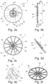
- the Figures 3a to 3f show the second stressing anchor 7, which is designed as a separate component for the stressing strand 2, according to the first preferred embodiment in an individual representation from different views.
- the Figure 3a shows the second tensioning anchor 7 in a rear view.
- the second turnbuckle 7 has a plate-shaped design with the round, completely closed outer contour 11 formed by the outer section 10 of the second turnbuckle 7 .
- the outer section 10 is arranged radially on the outside of the inner section 12 of the second turnbuckle 7 , which includes the inlet opening 13 which is arranged in the center of the plate-shaped second turnbuckle 7 .
- the inlet opening 13 is framed and/or delimited by the edge section 14 on the peripheral side and/or radially on the outside.
- the edge section 14 includes the four latching lugs 71-74 already mentioned.
- the four latching lugs 71-74 are delimited and/or defined in the circumferential direction within the inner section 12 by a respective slot-shaped material cutout 15, which each extends in the radial direction starting from the inlet opening 13.
- the Material recess 15 has a width extension D1 of essentially 0.8 mm and, starting from the center and/or the inlet opening 13, a length extension of D2/2 essentially 10 mm.
- the Figure 3b shows a sectional view of the second tensioning anchor 7 according to FIG Figure 3a drawn-in perspective A.
- the locking means 9 of the second tensioning anchor 7 are designed in such a way that the latching lugs 71-74 form the depression 16 in the inner section 12.
- the end piece 25 of the tensioning cord 2 can thus advantageously be arranged completely in the depression 16 after the loose end 4 of the tensioning cord 2 has been separated.
- the dimensions of the second tensioning anchor 7 according to the first preferred embodiment can be seen from the longitudinal section.
- the diameter D4 of the plate-shaped second tensioning anchor 7 is essentially 100 mm, with the outer section 10 in the area of the outer contour 11 having a thickness D6 of essentially 2 mm.
- the depth D5 of the depression 16 formed is essentially 5 mm.
- the 3c shows the second tensioning anchor 7 in a front view.
- the large number of stiffening elements 19 contained by the second tensioning anchor 7 can be seen, which extend from the inner section 12 in the radial direction over the outer section 10 to the outer contour 11 and thus form the force application surface 8 in the clamping state .
- FIGs 3d and 3e show a further sectional view of the second tensioning anchor 7 after that in FIG 3c drawn-in perspective C.
- the depression 16 formed by the locking lugs 71-74 is again and/or indentation visible.
- the Figure 3e which is an enlarged portion of the 3d is that the latching lugs 71-74 comprise an end surface 24 which is inclined towards the entry opening 13 and which is designed in such a way that, in the fixed state, it rests on the sliding surface 23 which is formed by the tension cord 2 in the locking area 5. Due to the inclined end face 24, the inlet opening 13 has a diameter D3 of essentially 2.2 mm, with two opposite end faces 24 spanning an angle ⁇ of essentially 60° in longitudinal section.
- the well-known second tensioning anchor 7 is shown in a perspective view.
- the web-shaped stiffening elements 19 can be seen, which extend in the radial direction in the plate-shaped second clamping anchor 7 and thus rest on one of the side surfaces in the clamped state in order to form the additional force application surface 8 .
- the storage unit 100 formed of cardboard is shown.
- the storage unit 100 includes four side walls 101-104, which laterally delimit a receiving space for bulk material.
- Storage unit 100 comprises a first clamping unit 1a for clamping the first and second side walls 101, 102 across the width of storage unit 100 and a second clamping unit 1b for clamping the third and fourth side walls 103, 104 across the length of storage unit 100.
- the first clamping anchor 3a of the first clamping unit 1a rests on the outside of the first side wall 101 in order to form a force application surface 6a for this side wall 101 and the second clamping anchor 7a of the first clamping unit 1a on the outside of the second Side wall 102 to form a further force application surface 8a for this side wall 102.
- the first clamping unit 1a and the second clamping unit 1b are the same component, with the second clamping anchor 7a of the first clamping unit 1a for clamping the storage unit 100 over the width extension in the first locking area 51a and the second clamping anchor 7b of the second clamping unit 1b for clamping of the storage unit 100 in length extension in the second locking area 52b.
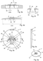
- Figure 5a shows a perspective view of a second turnbuckle 7 according to a second embodiment.
- the stressing anchor 7 has an outer section 10 with an outer contour 11 that is completely closed in the circumferential direction and an inner section 12 with an inlet opening 13 .
- the inlet opening 13 has a first section 26 with a larger cross section Q1, in particular with a larger radius, and a second section 27 with a smaller cross section Q2, in particular with a smaller radius.
- the first section 26 allows the free end 4 to be inserted and the rest of the tensioning cord 2 to be passed through.
- the first cross section Q1 is therefore larger than the maximum diameter or cross section Q1 of the tensioning cord 2.
- the smaller cross section Q2 of the second section 27 is designed in such a way that locking or hooking with the tension cord 2, in particular with locking areas 5, 51, 52, 53 of the tension cord 2, is made possible.
- a constriction 28 is arranged between the first section 26 and the second section 27 .
- the width of the constriction 28 is in a neutral or force-free or undeformed position is preferably smaller than the maximum width, in particular the diameter, of the second cross-section Q2 of the second section 27.
- the outer section 10 has a projection 31 on an outer edge, which is arranged essentially in the extension of a center point 32 of the first section 26 of the inlet opening 13 and a center point 33 of the second section 27 of the inlet opening 13 .
- the projection 31 can be used without tools or with appropriate tools to shift or relocate the stressing anchor 7 relative to the tendon strand 2 and thus transfer the tendon strand 2 from the second section 27 to the first section 26 or vice versa.
- the projection 31 is also in the side view Figure 5c of the tensioning anchor 7 according to the second embodiment clearly visible.
- the Figure 5d shows a sectional view through the tensioning anchor 7 of the second embodiment along the sectional plane AA of the representation of FIG Figure 5b .
- the sectional view shows that the material recesses 29 extend through the entire thickness or along the entire longitudinal direction L of the stressing anchor 7 .
- the Figure 5e shows a sectional view through the second tensioning anchor 7 along the sectional plane BB of the representation Figure 5b and with it one Sectional view along or at the level of the constriction 28 between the first section 26 and the second section 27.
- the material recesses 29 can also be seen again in this.
- the material webs 30 acting as springs, like the rest of the second section 27, have a cross section that widens in the longitudinal direction L, preferably in the form of a truncated cone. This can be particularly advantageous with the locking stages 61, 62, 63 as shown in the Figures 2a and 2b interact and bring about an effective and stable fastening or locking and thus ensure the clamping state.
- the Fig. 5f shows the in the Figure 5d Section Z shown in dashed lines in an enlarged view. This again shows the material recesses 29 laterally to the constriction 28 and the material webs 30 formed therefrom, which act as springs and bring about an elastic deformability of the constriction 28 .
- the Figure 6a shows a second stressing anchor 7 and a free end 4 of a tendon 2 in a release position or release arrangement of stressing anchor 7 and tendon 2 to each other.
- the tendon cord 2 runs through the first section 26 of the entry opening 13 .
- the Figure 6b shows a clamping state of the clamping unit 1.
- a corresponding prestress was first applied, for example by tensile forces on the tendon strand 2 and/or compressive forces on the stressing anchor 7 in the longitudinal direction L.
- a shearing force F was then applied to the stressing anchor 7 and/or applied to the tendon cord 2, so that the tendon cord 2, in particular in the area of a Arresting area 5 passes the constriction 28 of the stressing anchor 7 and the second section 27 of the inlet opening 13 encloses the arresting area 5, in particular an arresting step 61, 62, 63 in the circumferential direction almost completely and in the longitudinal direction as far as possible in a form-fitting manner.
- the protruding end of the tension cord 7 can be cut to length, in particular cut off or pinched off.
Landscapes
- Engineering & Computer Science (AREA)
- General Engineering & Computer Science (AREA)
- Mechanical Engineering (AREA)
- Clamps And Clips (AREA)
Applications Claiming Priority (2)
| Application Number | Priority Date | Filing Date | Title |
|---|---|---|---|
| DE102021133931 | 2021-12-20 | ||
| DE102022107208.8A DE102022107208B3 (de) | 2021-12-20 | 2022-03-28 | Spanneinheit und Vorratseinheit mit wenigstens einer Spanneinheit |
Publications (3)
| Publication Number | Publication Date |
|---|---|
| EP4201831A1 true EP4201831A1 (fr) | 2023-06-28 |
| EP4201831C0 EP4201831C0 (fr) | 2025-03-19 |
| EP4201831B1 EP4201831B1 (fr) | 2025-03-19 |
Family
ID=84901205
Family Applications (1)
| Application Number | Title | Priority Date | Filing Date |
|---|---|---|---|
| EP22214894.2A Active EP4201831B1 (fr) | 2021-12-20 | 2022-12-20 | Unité de serrage et unité de stockage dotée d'au moins une unité de serrage |
Country Status (1)
| Country | Link |
|---|---|
| EP (1) | EP4201831B1 (fr) |
Citations (8)
| Publication number | Priority date | Publication date | Assignee | Title |
|---|---|---|---|---|
| US3938587A (en) * | 1975-01-06 | 1976-02-17 | Hayden Trans-Cooler, Inc. | Cooler fastening system |
| FR2673250A1 (fr) * | 1991-02-26 | 1992-08-28 | Otis Elevator Co | Dispositif de fixation invisible d'une platine sur une plaque d'applique. |
| DE202005019632U1 (de) * | 2005-12-13 | 2006-03-30 | Bächle, Dieter | Spannsystem zum Abspannen von gegenüberliegenden Kartonwänden im Inneren eines Kartons |
| DE202006015624U1 (de) | 2005-12-13 | 2007-04-26 | Bächle, Dieter | Behältnis mit begrenzt flexiblen Wänden und Spannstrang für diese |
| US20140072386A1 (en) * | 2012-09-13 | 2014-03-13 | Pierce A. Baugh, SR. | Fastener Replacing a Bolt or Rivet |
| EP2865902A1 (fr) | 2013-10-28 | 2015-04-29 | Peter Wey | Dispositif de liaison pour un système de construction et système de construction |
| US20170045073A1 (en) * | 2015-08-13 | 2017-02-16 | Jijun Liu | EZ fastener series |
| GB2541495A (en) * | 2015-06-01 | 2017-02-22 | John England Matthew | Locking member for fixing mesh material |
-
2022
- 2022-12-20 EP EP22214894.2A patent/EP4201831B1/fr active Active
Patent Citations (8)
| Publication number | Priority date | Publication date | Assignee | Title |
|---|---|---|---|---|
| US3938587A (en) * | 1975-01-06 | 1976-02-17 | Hayden Trans-Cooler, Inc. | Cooler fastening system |
| FR2673250A1 (fr) * | 1991-02-26 | 1992-08-28 | Otis Elevator Co | Dispositif de fixation invisible d'une platine sur une plaque d'applique. |
| DE202005019632U1 (de) * | 2005-12-13 | 2006-03-30 | Bächle, Dieter | Spannsystem zum Abspannen von gegenüberliegenden Kartonwänden im Inneren eines Kartons |
| DE202006015624U1 (de) | 2005-12-13 | 2007-04-26 | Bächle, Dieter | Behältnis mit begrenzt flexiblen Wänden und Spannstrang für diese |
| US20140072386A1 (en) * | 2012-09-13 | 2014-03-13 | Pierce A. Baugh, SR. | Fastener Replacing a Bolt or Rivet |
| EP2865902A1 (fr) | 2013-10-28 | 2015-04-29 | Peter Wey | Dispositif de liaison pour un système de construction et système de construction |
| GB2541495A (en) * | 2015-06-01 | 2017-02-22 | John England Matthew | Locking member for fixing mesh material |
| US20170045073A1 (en) * | 2015-08-13 | 2017-02-16 | Jijun Liu | EZ fastener series |
Also Published As
| Publication number | Publication date |
|---|---|
| EP4201831C0 (fr) | 2025-03-19 |
| EP4201831B1 (fr) | 2025-03-19 |
Similar Documents
| Publication | Publication Date | Title |
|---|---|---|
| DE2633972C3 (de) | Anordnung zum Verbinden zweier Bauteile | |
| EP1442942A1 (fr) | Raccord à brides entre un longeron de véhicule et un élément de support fixable à ce dernier | |
| EP4357627B1 (fr) | Dispositif de compensation de tolérance | |
| EP0949424A2 (fr) | Raccord entre composants, en particulier pour panneaux | |
| DE4322253A1 (de) | Schalung mit Schaltafeln und Verbindungsmitteln | |
| DE2747064A1 (de) | Schalungselement | |
| EP0698720B2 (fr) | Procédé de fixation d'équerres d'assemblage, de prérérence en matière plastique soudable, ainsi qu'équerres y afférant | |
| EP0903265A2 (fr) | Dispositif absorbeur d'énergie pour un véhicule | |
| EP0685403B1 (fr) | Dispositif de connection | |
| EP0628734B1 (fr) | Dispositif de fixation pour relier de manière amovible un tube polygonal, en particulier un tube à profil rectangulaire | |
| WO2013131509A1 (fr) | Dispositif pour fixer un rail | |
| EP3546324B1 (fr) | Dispositif pare-chocs pour un véhicule automobile | |
| DE19923487B4 (de) | Widerlager mit Formteil zum Befestigen von Betätigungszügen | |
| EP2698295A2 (fr) | Tube télescopique réglable en longueur, béquille télescopique et procédé de montage | |
| DE102022107208B3 (de) | Spanneinheit und Vorratseinheit mit wenigstens einer Spanneinheit | |
| EP4201831A1 (fr) | Unité de serrage et unité de stockage dotée d'au moins une unité de serrage | |
| DE102006009304B3 (de) | Lenksäulenanordnung für Fahrzeuge | |
| DE9113235U1 (de) | Eckverbinder | |
| DE3138530C2 (de) | Verbindungsvorrichtung | |
| EP2987924B1 (fr) | Porte-butée pour coffrage mural | |
| WO1991019116A1 (fr) | Unite de guidage et montage de ressorts de pression | |
| DE10225403A1 (de) | Ständerwerk | |
| DE2824301C2 (de) | Vorrichtung zum Verbinden eines Fensterblend- oder eines Türrahmens mit einem Rolladenkasten | |
| DE2218832A1 (de) | Hebeklemme | |
| EP0359857B1 (fr) | Goupille de charnière |
Legal Events
| Date | Code | Title | Description |
|---|---|---|---|
| PUAI | Public reference made under article 153(3) epc to a published international application that has entered the european phase |
Free format text: ORIGINAL CODE: 0009012 |
|
| STAA | Information on the status of an ep patent application or granted ep patent |
Free format text: STATUS: THE APPLICATION HAS BEEN PUBLISHED |
|
| AK | Designated contracting states |
Kind code of ref document: A1 Designated state(s): AL AT BE BG CH CY CZ DE DK EE ES FI FR GB GR HR HU IE IS IT LI LT LU LV MC ME MK MT NL NO PL PT RO RS SE SI SK SM TR |
|
| STAA | Information on the status of an ep patent application or granted ep patent |
Free format text: STATUS: REQUEST FOR EXAMINATION WAS MADE |
|
| 17P | Request for examination filed |
Effective date: 20231218 |
|
| RBV | Designated contracting states (corrected) |
Designated state(s): AL AT BE BG CH CY CZ DE DK EE ES FI FR GB GR HR HU IE IS IT LI LT LU LV MC ME MK MT NL NO PL PT RO RS SE SI SK SM TR |
|
| GRAP | Despatch of communication of intention to grant a patent |
Free format text: ORIGINAL CODE: EPIDOSNIGR1 |
|
| STAA | Information on the status of an ep patent application or granted ep patent |
Free format text: STATUS: GRANT OF PATENT IS INTENDED |
|
| RIC1 | Information provided on ipc code assigned before grant |
Ipc: F16B 21/09 20060101ALN20241025BHEP Ipc: F16B 21/07 20060101ALN20241025BHEP Ipc: F16B 19/02 20060101ALI20241025BHEP Ipc: F16B 2/12 20060101ALI20241025BHEP Ipc: B65D 5/44 20060101AFI20241025BHEP |
|
| INTG | Intention to grant announced |
Effective date: 20241111 |
|
| RIC1 | Information provided on ipc code assigned before grant |
Ipc: F16B 21/09 20060101ALN20241104BHEP Ipc: F16B 21/07 20060101ALN20241104BHEP Ipc: F16B 19/02 20060101ALI20241104BHEP Ipc: F16B 2/12 20060101ALI20241104BHEP Ipc: B65D 5/44 20060101AFI20241104BHEP |
|
| GRAS | Grant fee paid |
Free format text: ORIGINAL CODE: EPIDOSNIGR3 |
|
| GRAA | (expected) grant |
Free format text: ORIGINAL CODE: 0009210 |
|
| STAA | Information on the status of an ep patent application or granted ep patent |
Free format text: STATUS: THE PATENT HAS BEEN GRANTED |
|
| AK | Designated contracting states |
Kind code of ref document: B1 Designated state(s): AL AT BE BG CH CY CZ DE DK EE ES FI FR GB GR HR HU IE IS IT LI LT LU LV MC ME MK MT NL NO PL PT RO RS SE SI SK SM TR |
|
| REG | Reference to a national code |
Ref country code: GB Ref legal event code: FG4D Free format text: NOT ENGLISH |
|
| REG | Reference to a national code |
Ref country code: CH Ref legal event code: EP |
|
| REG | Reference to a national code |
Ref country code: DE Ref legal event code: R096 Ref document number: 502022003246 Country of ref document: DE |
|
| REG | Reference to a national code |
Ref country code: IE Ref legal event code: FG4D Free format text: LANGUAGE OF EP DOCUMENT: GERMAN |
|
| U01 | Request for unitary effect filed |
Effective date: 20250417 |
|
| U07 | Unitary effect registered |
Designated state(s): AT BE BG DE DK EE FI FR IT LT LU LV MT NL PT RO SE SI Effective date: 20250424 |
|
| PG25 | Lapsed in a contracting state [announced via postgrant information from national office to epo] |
Ref country code: RS Free format text: LAPSE BECAUSE OF FAILURE TO SUBMIT A TRANSLATION OF THE DESCRIPTION OR TO PAY THE FEE WITHIN THE PRESCRIBED TIME-LIMIT Effective date: 20250619 |
|
| PG25 | Lapsed in a contracting state [announced via postgrant information from national office to epo] |
Ref country code: NO Free format text: LAPSE BECAUSE OF FAILURE TO SUBMIT A TRANSLATION OF THE DESCRIPTION OR TO PAY THE FEE WITHIN THE PRESCRIBED TIME-LIMIT Effective date: 20250619 |
|
| PG25 | Lapsed in a contracting state [announced via postgrant information from national office to epo] |
Ref country code: HR Free format text: LAPSE BECAUSE OF FAILURE TO SUBMIT A TRANSLATION OF THE DESCRIPTION OR TO PAY THE FEE WITHIN THE PRESCRIBED TIME-LIMIT Effective date: 20250319 |
|
| PG25 | Lapsed in a contracting state [announced via postgrant information from national office to epo] |
Ref country code: GR Free format text: LAPSE BECAUSE OF FAILURE TO SUBMIT A TRANSLATION OF THE DESCRIPTION OR TO PAY THE FEE WITHIN THE PRESCRIBED TIME-LIMIT Effective date: 20250620 |
|
| PG25 | Lapsed in a contracting state [announced via postgrant information from national office to epo] |
Ref country code: SM Free format text: LAPSE BECAUSE OF FAILURE TO SUBMIT A TRANSLATION OF THE DESCRIPTION OR TO PAY THE FEE WITHIN THE PRESCRIBED TIME-LIMIT Effective date: 20250319 |
|
| PG25 | Lapsed in a contracting state [announced via postgrant information from national office to epo] |
Ref country code: ES Free format text: LAPSE BECAUSE OF FAILURE TO SUBMIT A TRANSLATION OF THE DESCRIPTION OR TO PAY THE FEE WITHIN THE PRESCRIBED TIME-LIMIT Effective date: 20250319 |
|
| PG25 | Lapsed in a contracting state [announced via postgrant information from national office to epo] |
Ref country code: PL Free format text: LAPSE BECAUSE OF FAILURE TO SUBMIT A TRANSLATION OF THE DESCRIPTION OR TO PAY THE FEE WITHIN THE PRESCRIBED TIME-LIMIT Effective date: 20250319 |
|
| PG25 | Lapsed in a contracting state [announced via postgrant information from national office to epo] |
Ref country code: CZ Free format text: LAPSE BECAUSE OF FAILURE TO SUBMIT A TRANSLATION OF THE DESCRIPTION OR TO PAY THE FEE WITHIN THE PRESCRIBED TIME-LIMIT Effective date: 20250319 |
|
| PG25 | Lapsed in a contracting state [announced via postgrant information from national office to epo] |
Ref country code: SK Free format text: LAPSE BECAUSE OF FAILURE TO SUBMIT A TRANSLATION OF THE DESCRIPTION OR TO PAY THE FEE WITHIN THE PRESCRIBED TIME-LIMIT Effective date: 20250319 |
|
| PG25 | Lapsed in a contracting state [announced via postgrant information from national office to epo] |
Ref country code: IS Free format text: LAPSE BECAUSE OF FAILURE TO SUBMIT A TRANSLATION OF THE DESCRIPTION OR TO PAY THE FEE WITHIN THE PRESCRIBED TIME-LIMIT Effective date: 20250719 |
|
| REG | Reference to a national code |
Ref country code: CH Ref legal event code: U11 Free format text: ST27 STATUS EVENT CODE: U-0-0-U10-U11 (AS PROVIDED BY THE NATIONAL OFFICE) Effective date: 20260122 |
|
| PLBE | No opposition filed within time limit |
Free format text: ORIGINAL CODE: 0009261 |
|
| STAA | Information on the status of an ep patent application or granted ep patent |
Free format text: STATUS: NO OPPOSITION FILED WITHIN TIME LIMIT |
|
| REG | Reference to a national code |
Ref country code: CH Ref legal event code: L10 Free format text: ST27 STATUS EVENT CODE: U-0-0-L10-L00 (AS PROVIDED BY THE NATIONAL OFFICE) Effective date: 20260128 |
|
| U20 | Renewal fee for the european patent with unitary effect paid |
Year of fee payment: 4 Effective date: 20251222 |
|
| 26N | No opposition filed |
Effective date: 20251222 |
|
| PGFP | Annual fee paid to national office [announced via postgrant information from national office to epo] |
Ref country code: CH Payment date: 20260122 Year of fee payment: 4 |