EP4202184A1 - Gasturbine mit einer erhitzten turbinenauslassleitschaufelanordnung - Google Patents
Gasturbine mit einer erhitzten turbinenauslassleitschaufelanordnung Download PDFInfo
- Publication number
- EP4202184A1 EP4202184A1 EP22213343.1A EP22213343A EP4202184A1 EP 4202184 A1 EP4202184 A1 EP 4202184A1 EP 22213343 A EP22213343 A EP 22213343A EP 4202184 A1 EP4202184 A1 EP 4202184A1
- Authority
- EP
- European Patent Office
- Prior art keywords
- turbine
- radially
- liner
- annular member
- arrangement
- Prior art date
- Legal status (The legal status is an assumption and is not a legal conclusion. Google has not performed a legal analysis and makes no representation as to the accuracy of the status listed.)
- Pending
Links
Images


Classifications
-
- F—MECHANICAL ENGINEERING; LIGHTING; HEATING; WEAPONS; BLASTING
- F01—MACHINES OR ENGINES IN GENERAL; ENGINE PLANTS IN GENERAL; STEAM ENGINES
- F01D—NON-POSITIVE DISPLACEMENT MACHINES OR ENGINES, e.g. STEAM TURBINES
- F01D9/00—Stators
- F01D9/02—Nozzles; Nozzle boxes; Stator blades; Guide conduits, e.g. individual nozzles
- F01D9/04—Nozzles; Nozzle boxes; Stator blades; Guide conduits, e.g. individual nozzles forming ring or sector
- F01D9/042—Nozzles; Nozzle boxes; Stator blades; Guide conduits, e.g. individual nozzles forming ring or sector fixing blades to stators
-
- F—MECHANICAL ENGINEERING; LIGHTING; HEATING; WEAPONS; BLASTING
- F01—MACHINES OR ENGINES IN GENERAL; ENGINE PLANTS IN GENERAL; STEAM ENGINES
- F01D—NON-POSITIVE DISPLACEMENT MACHINES OR ENGINES, e.g. STEAM TURBINES
- F01D25/00—Component parts, details, or accessories, not provided for in, or of interest apart from, other groups
- F01D25/08—Cooling; Heating; Heat-insulation
- F01D25/14—Casings modified therefor
-
- F—MECHANICAL ENGINEERING; LIGHTING; HEATING; WEAPONS; BLASTING
- F01—MACHINES OR ENGINES IN GENERAL; ENGINE PLANTS IN GENERAL; STEAM ENGINES
- F01D—NON-POSITIVE DISPLACEMENT MACHINES OR ENGINES, e.g. STEAM TURBINES
- F01D11/00—Preventing or minimising internal leakage of working-fluid, e.g. between stages
- F01D11/02—Preventing or minimising internal leakage of working-fluid, e.g. between stages by non-contact sealings, e.g. of labyrinth type
-
- F—MECHANICAL ENGINEERING; LIGHTING; HEATING; WEAPONS; BLASTING
- F01—MACHINES OR ENGINES IN GENERAL; ENGINE PLANTS IN GENERAL; STEAM ENGINES
- F01D—NON-POSITIVE DISPLACEMENT MACHINES OR ENGINES, e.g. STEAM TURBINES
- F01D11/00—Preventing or minimising internal leakage of working-fluid, e.g. between stages
- F01D11/08—Preventing or minimising internal leakage of working-fluid, e.g. between stages for sealing space between rotor blade tips and stator
- F01D11/10—Preventing or minimising internal leakage of working-fluid, e.g. between stages for sealing space between rotor blade tips and stator using sealing fluid, e.g. steam
-
- F—MECHANICAL ENGINEERING; LIGHTING; HEATING; WEAPONS; BLASTING
- F01—MACHINES OR ENGINES IN GENERAL; ENGINE PLANTS IN GENERAL; STEAM ENGINES
- F01D—NON-POSITIVE DISPLACEMENT MACHINES OR ENGINES, e.g. STEAM TURBINES
- F01D11/00—Preventing or minimising internal leakage of working-fluid, e.g. between stages
- F01D11/08—Preventing or minimising internal leakage of working-fluid, e.g. between stages for sealing space between rotor blade tips and stator
- F01D11/12—Preventing or minimising internal leakage of working-fluid, e.g. between stages for sealing space between rotor blade tips and stator using a rubstrip, e.g. erodible. deformable or resiliently-biased part
- F01D11/127—Preventing or minimising internal leakage of working-fluid, e.g. between stages for sealing space between rotor blade tips and stator using a rubstrip, e.g. erodible. deformable or resiliently-biased part with a deformable or crushable structure, e.g. honeycomb
-
- F—MECHANICAL ENGINEERING; LIGHTING; HEATING; WEAPONS; BLASTING
- F01—MACHINES OR ENGINES IN GENERAL; ENGINE PLANTS IN GENERAL; STEAM ENGINES
- F01D—NON-POSITIVE DISPLACEMENT MACHINES OR ENGINES, e.g. STEAM TURBINES
- F01D25/00—Component parts, details, or accessories, not provided for in, or of interest apart from, other groups
- F01D25/08—Cooling; Heating; Heat-insulation
- F01D25/10—Heating, e.g. warming-up before starting
-
- F—MECHANICAL ENGINEERING; LIGHTING; HEATING; WEAPONS; BLASTING
- F01—MACHINES OR ENGINES IN GENERAL; ENGINE PLANTS IN GENERAL; STEAM ENGINES
- F01D—NON-POSITIVE DISPLACEMENT MACHINES OR ENGINES, e.g. STEAM TURBINES
- F01D25/00—Component parts, details, or accessories, not provided for in, or of interest apart from, other groups
- F01D25/24—Casings; Casing parts, e.g. diaphragms, casing fastenings
- F01D25/246—Fastening of diaphragms or stator-rings
-
- F—MECHANICAL ENGINEERING; LIGHTING; HEATING; WEAPONS; BLASTING
- F01—MACHINES OR ENGINES IN GENERAL; ENGINE PLANTS IN GENERAL; STEAM ENGINES
- F01D—NON-POSITIVE DISPLACEMENT MACHINES OR ENGINES, e.g. STEAM TURBINES
- F01D25/00—Component parts, details, or accessories, not provided for in, or of interest apart from, other groups
- F01D25/24—Casings; Casing parts, e.g. diaphragms, casing fastenings
- F01D25/26—Double casings; Measures against temperature strain in casings
-
- F—MECHANICAL ENGINEERING; LIGHTING; HEATING; WEAPONS; BLASTING
- F01—MACHINES OR ENGINES IN GENERAL; ENGINE PLANTS IN GENERAL; STEAM ENGINES
- F01D—NON-POSITIVE DISPLACEMENT MACHINES OR ENGINES, e.g. STEAM TURBINES
- F01D25/00—Component parts, details, or accessories, not provided for in, or of interest apart from, other groups
- F01D25/30—Exhaust heads, chambers, or the like
-
- F—MECHANICAL ENGINEERING; LIGHTING; HEATING; WEAPONS; BLASTING
- F01—MACHINES OR ENGINES IN GENERAL; ENGINE PLANTS IN GENERAL; STEAM ENGINES
- F01D—NON-POSITIVE DISPLACEMENT MACHINES OR ENGINES, e.g. STEAM TURBINES
- F01D5/00—Blades; Blade-carrying members; Heating, heat-insulating, cooling or antivibration means on the blades or the members
- F01D5/02—Blade-carrying members, e.g. rotors
- F01D5/08—Heating, heat-insulating or cooling means
- F01D5/081—Cooling fluid being directed on the side of the rotor disc or at the roots of the blades
-
- F—MECHANICAL ENGINEERING; LIGHTING; HEATING; WEAPONS; BLASTING
- F01—MACHINES OR ENGINES IN GENERAL; ENGINE PLANTS IN GENERAL; STEAM ENGINES
- F01D—NON-POSITIVE DISPLACEMENT MACHINES OR ENGINES, e.g. STEAM TURBINES
- F01D5/00—Blades; Blade-carrying members; Heating, heat-insulating, cooling or antivibration means on the blades or the members
- F01D5/12—Blades
- F01D5/14—Form or construction
- F01D5/20—Specially-shaped blade tips to seal space between tips and stator
-
- F—MECHANICAL ENGINEERING; LIGHTING; HEATING; WEAPONS; BLASTING
- F01—MACHINES OR ENGINES IN GENERAL; ENGINE PLANTS IN GENERAL; STEAM ENGINES
- F01D—NON-POSITIVE DISPLACEMENT MACHINES OR ENGINES, e.g. STEAM TURBINES
- F01D9/00—Stators
- F01D9/02—Nozzles; Nozzle boxes; Stator blades; Guide conduits, e.g. individual nozzles
- F01D9/04—Nozzles; Nozzle boxes; Stator blades; Guide conduits, e.g. individual nozzles forming ring or sector
- F01D9/041—Nozzles; Nozzle boxes; Stator blades; Guide conduits, e.g. individual nozzles forming ring or sector using blades
-
- F—MECHANICAL ENGINEERING; LIGHTING; HEATING; WEAPONS; BLASTING
- F01—MACHINES OR ENGINES IN GENERAL; ENGINE PLANTS IN GENERAL; STEAM ENGINES
- F01D—NON-POSITIVE DISPLACEMENT MACHINES OR ENGINES, e.g. STEAM TURBINES
- F01D9/00—Stators
- F01D9/06—Fluid supply conduits to nozzles or the like
-
- F—MECHANICAL ENGINEERING; LIGHTING; HEATING; WEAPONS; BLASTING
- F02—COMBUSTION ENGINES; HOT-GAS OR COMBUSTION-PRODUCT ENGINE PLANTS
- F02C—GAS-TURBINE PLANTS; AIR INTAKES FOR JET-PROPULSION PLANTS; CONTROLLING FUEL SUPPLY IN AIR-BREATHING JET-PROPULSION PLANTS
- F02C3/00—Gas-turbine plants characterised by the use of combustion products as the working fluid
- F02C3/04—Gas-turbine plants characterised by the use of combustion products as the working fluid having a turbine driving a compressor
- F02C3/107—Gas-turbine plants characterised by the use of combustion products as the working fluid having a turbine driving a compressor with two or more rotors connected by power transmission
-
- F—MECHANICAL ENGINEERING; LIGHTING; HEATING; WEAPONS; BLASTING
- F02—COMBUSTION ENGINES; HOT-GAS OR COMBUSTION-PRODUCT ENGINE PLANTS
- F02K—JET-PROPULSION PLANTS
- F02K3/00—Plants including a gas turbine driving a compressor or a ducted fan
- F02K3/02—Plants including a gas turbine driving a compressor or a ducted fan in which part of the working fluid by-passes the turbine and combustion chamber
- F02K3/04—Plants including a gas turbine driving a compressor or a ducted fan in which part of the working fluid by-passes the turbine and combustion chamber the plant including ducted fans, i.e. fans with high volume, low pressure outputs, for augmenting the jet thrust, e.g. of double-flow type
- F02K3/06—Plants including a gas turbine driving a compressor or a ducted fan in which part of the working fluid by-passes the turbine and combustion chamber the plant including ducted fans, i.e. fans with high volume, low pressure outputs, for augmenting the jet thrust, e.g. of double-flow type with front fan
-
- F—MECHANICAL ENGINEERING; LIGHTING; HEATING; WEAPONS; BLASTING
- F05—INDEXING SCHEMES RELATING TO ENGINES OR PUMPS IN VARIOUS SUBCLASSES OF CLASSES F01-F04
- F05D—INDEXING SCHEME FOR ASPECTS RELATING TO NON-POSITIVE-DISPLACEMENT MACHINES OR ENGINES, GAS-TURBINES OR JET-PROPULSION PLANTS
- F05D2240/00—Components
- F05D2240/10—Stators
- F05D2240/14—Casings or housings protecting or supporting assemblies within
-
- F—MECHANICAL ENGINEERING; LIGHTING; HEATING; WEAPONS; BLASTING
- F05—INDEXING SCHEMES RELATING TO ENGINES OR PUMPS IN VARIOUS SUBCLASSES OF CLASSES F01-F04
- F05D—INDEXING SCHEME FOR ASPECTS RELATING TO NON-POSITIVE-DISPLACEMENT MACHINES OR ENGINES, GAS-TURBINES OR JET-PROPULSION PLANTS
- F05D2240/00—Components
- F05D2240/55—Seals
-
- F—MECHANICAL ENGINEERING; LIGHTING; HEATING; WEAPONS; BLASTING
- F05—INDEXING SCHEMES RELATING TO ENGINES OR PUMPS IN VARIOUS SUBCLASSES OF CLASSES F01-F04
- F05D—INDEXING SCHEME FOR ASPECTS RELATING TO NON-POSITIVE-DISPLACEMENT MACHINES OR ENGINES, GAS-TURBINES OR JET-PROPULSION PLANTS
- F05D2260/00—Function
- F05D2260/20—Heat transfer, e.g. cooling
- F05D2260/221—Improvement of heat transfer
- F05D2260/2214—Improvement of heat transfer by increasing the heat transfer surface
- F05D2260/22141—Improvement of heat transfer by increasing the heat transfer surface using fins or ribs
-
- Y—GENERAL TAGGING OF NEW TECHNOLOGICAL DEVELOPMENTS; GENERAL TAGGING OF CROSS-SECTIONAL TECHNOLOGIES SPANNING OVER SEVERAL SECTIONS OF THE IPC; TECHNICAL SUBJECTS COVERED BY FORMER USPC CROSS-REFERENCE ART COLLECTIONS [XRACs] AND DIGESTS
- Y02—TECHNOLOGIES OR APPLICATIONS FOR MITIGATION OR ADAPTATION AGAINST CLIMATE CHANGE
- Y02T—CLIMATE CHANGE MITIGATION TECHNOLOGIES RELATED TO TRANSPORTATION
- Y02T50/00—Aeronautics or air transport
- Y02T50/60—Efficient propulsion technologies, e.g. for aircraft
Definitions
- the present disclosure relates to a turbine arrangement including an outlet stator vane arrangement and in particular to a turbine arrangement including an outlet stator vane arrangement for a gas turbine engine.
- a radially outer annular member of the outlet stator vane arrangement of the turbine arrangement of an aero gas turbine engine is commonly provided with radially outwardly extending lugs which are used to mount the gas turbine engine onto the aircraft structure for example an aircraft pylon.
- a radially inner annular member of the outlet stator vane arrangement of the turbine arrangement supports a bearing in which a turbine is rotatably mounted.
- the radially outer annular member and the lugs form a relatively massive and stiff structure to withstand the mechanical loads coming from the mount to the aircraft structure and also to support the turbine via the bearing.
- the outlet stator vane arrangement is subjected to hot gases flowing out of the turbine and thus the radially outer annular member and the vanes of the outlet stator vane arrangement are subjected to the hot gases.
- the radially outer annular member and the lugs heat up relatively slowly due to their relatively high mass whereas the vanes heat up relatively quickly due to their relatively low mass, for example when the gas turbine engine is started from ambient temperature and operated at up to maximum power conditions, e.g. take off.
- the outlet stator vane arrangement is a relatively expensive component of a gas turbine engine and is expensive to replace.
- the present disclosure seeks to provide a turbine arrangement including an outlet stator vane arrangement which reduces or overcomes the above mentioned problem.
- the present disclosure provides a turbine arrangement, and a gas turbine engine, as set out in the appended claims.
- a turbine arrangement including a turbine rotor arrangement, a turbine seal arrangement and a turbine outlet stator vane arrangement;
- Managing the temperature of the radially outer annular member may mean heating the radially outer annular member. Alternatively it may mean reducing the temperature of the radially outer annular member. In this way the turbine arrangement of the present disclosure provides a thermal management functionality.
- the radially inner surface of the turbine shrouds may be arranged at a first radius, the turbine seal arrangement being arranged at a second radius, the upstream end of the liner having a radially outer surface, the radially outer surface at the upstream end of the liner being arranged at a third radius wherein the third radius is equal to or greater than the first radius and less than the second radius.
- the radially outer annular member may have a plurality of radially inwardly extending hooks and the liner having a plurality of radially outwardly extending hooks to engage the radially inwardly extending hooks on the radially outer annular member.
- the radially outer annular member may have a first annular radially inwardly extending hook and a second annular radially inwardly extending hook spaced axially from the first annular radially inwardly extending hook.
- the liner may have a first plurality of circumferentially spaced radially outwardly extending hooks and a second plurality of circumferentially spaced radially outwardly extending hooks spaced axially from the first plurality of circumferentially spaced radially outwardly extending hooks.
- the liner may comprise a plurality of circumferentially arranged liner panels.
- Each liner panel may have circumferentially spaced edges, the circumferentially spaced edges are shaped to correspond to the shape of the vanes.
- Each liner panel may have at least one radially outwardly extending hook at an upstream end and at least one radially outwardly extending hook at a downstream end.
- Each liner panel may have two circumferentially spaced radially outwardly extending hooks at an upstream end and two circumferentially spaced radially outwardly extending hooks at the downstream end.
- the radially inner surface of the radially outer annular member may have at least one heat transfer augmentation feature extending radially inwardly therefrom.
- the at least one heat transfer augmentation feature may be arranged between the first annular radially inwardly extending hook and the second annular radially inwardly extending hook.
- the radially inner surface of the radially outer annular member may have at least one circumferentially extending rib extending radially inwardly therefrom.
- the radially inner surface of the radially outer annular member may have a plurality of axially spaced circumferentially extending ribs extending radially inwardly therefrom. There may be one or more annular ribs.
- The, or each, annular rib may be positioned upstream of the leading edges of the vanes or downstream of the trailing edges of the vanes.
- the radially inner surface of the radially outer annular member may have a plurality of pedestals extending radially inwardly therefrom.
- the pedestals may be arranged in a plurality of axially spaced rows.
- the pedestals may be circular, triangular, square, rectangular or other suitable shape in cross-section.
- the radially outer surface of the liner may have at least one heat transfer augmentation feature extending radially outwardly therefrom.
- the at least one heat transfer augmentation feature may be arranged between the first plurality of circumferentially spaced radially outwardly extending hooks and the second plurality of circumferentially spaced radially outwardly extending hooks.
- the radially outer surface of the liner may have at least one circumferentially extending rib extending radially outwardly therefrom.
- the radially outer surface of the liner may have a plurality of axially spaced circumferentially extending ribs extending radially outwardly therefrom.
- the radially outer surface of the liner may have a plurality of pedestals extending radially outwardly therefrom.
- the pedestals may be arranged in a plurality of axially spaced rows.
- the pedestals may be circular, triangular, square, rectangular or other suitable shape in cross-section.
- the ribs on the radially inner surface of the radially outer annular member may be arranged axially alternately with the ribs on the radially outer surface of the liner.
- the rows of pedestals on the radially inner surface of the radially outer annular member may be arranged axially alternately with the rows of pedestals on the radially outer surface of the liner.
- the pedestals in the rows of pedestals on the radially inner surface of the radially outer annular member may be staggered circumferentially with respect to the pedestals in the rows of pedestals on the liner.
- the ribs on the radially inner surface of the radially outer annular member may be arranged axially alternately with rows of pedestals on the outer surface of the liner.
- the rows of pedestals on the radially inner surface of the radially outer annular member may be arranged axially alternately with ribs on the radially outer surface of the liner.
- the pedestals may be circular, triangular, square, rectangular or other suitable shape in cross-section.
- the upstream end of the liner may curve radially outwardly such that the radially inner surface of the liner and the radially outer surface of the liner curve radially outwardly in an upstream direction.
- the downstream end of the liner may curve radially inwardly such that the radially inner surface of the liner and the radially outer surface of the liner curve radially inwardly in a downstream direction.
- the radially outer annular member may have at least one radially outwardly extending flange or at least one radially outwardly extending lug whereby in operation the at least one flange or the at least one lug is secured to an aircraft pylon.
- the radially outer annular member may have a first radially outwardly extending flange and a second radially outwardly extending flange spaced axially from the first radially outwardly extending flange, whereby in operation the flanges are secured to the aircraft pylon.
- the radially outer annular member may have a first radially outwardly extending lug and a second radially outwardly extending lug spaced axially from the first radially outwardly extending lug, whereby in operation the lugs are secured to the aircraft pylon.
- a support structure may extend radially inwardly from the radially inner annular member and the support structure supporting a bearing, the bearing rotatably mounting the rotor of the turbine rotor arrangement.
- the radially inner annular member may have a radially outer surface, a second liner being spaced radially outwardly from the radially outer surface of the radially inner annular member to define a chamber having an inlet at an upstream end and an outlet at a downstream end.
- the radially inner annular member may have a plurality of radially outwardly extending hooks and the second liner having a plurality of radially inwardly extending hooks to engage the radially outwardly extending hooks on the radially inner annular member.
- the radially inner annular member may have a first annular radially outwardly extending hook and a second annular radially outwardly extending hook spaced axially from the first annular radially outwardly extending hook.
- the second liner may have a first plurality of circumferentially spaced radially inwardly extending hooks and a second plurality of circumferentially spaced radially inwardly extending hooks spaced axially from the first plurality of circumferentially spaced radially inwardly extending hooks.
- the second liner may comprise a plurality of circumferentially arranged liner panels.
- Each liner panel may have circumferentially spaced edges, the circumferentially spaced edges are shaped to correspond to the shape of the vanes.
- Each liner panel may have at least one radially inwardly extending hook at an upstream end and at least one radially inwardly extending hook at a downstream end.
- Each liner panel may have two circumferentially spaced radially inwardly extending hooks at an upstream end and two circumferentially spaced radially inwardly extending hooks at the downstream end.
- the radially outer surface of the radially inner annular member may have at least one heat transfer augmentation feature extending radially outwardly therefrom.
- the at least one heat transfer augmentation feature may be arranged between the first annular radially outwardly extending hook and the second annular radially outwardly extending hook.
- the radially outer surface of the radially inner annular member may have at least one circumferentially extending rib extending radially outwardly therefrom.
- the radially outer surface of the radially inner annular member may have a plurality of axially spaced circumferentially extending ribs extending radially outwardly therefrom. There may be one or more annular ribs.
- The, or each, annular rib may be positioned upstream of the leading edges of the vanes or downstream of the trailing edges of the vanes.
- the radially outer surface of the radially inner annular member may have a plurality of pedestals extending radially outwardly therefrom.
- the pedestals may be arranged in a plurality of axially spaced rows.
- the pedestals may be circular, triangular, square, rectangular or other suitable shape in cross-section.
- the radially inner surface of the second liner may have at least one heat transfer augmentation feature extending radially inwardly therefrom.
- the at least one heat transfer augmentation feature may be arranged between the first plurality of circumferentially spaced radially inwardly extending hooks and the second plurality of circumferentially spaced radially inwardly extending hooks.
- the radially inner surface of the second liner may have at least one circumferentially extending rib extending radially inwardly therefrom.
- the radially inner surface of the second liner may have a plurality of axially spaced circumferentially extending ribs extending radially inwardly therefrom.
- the radially inner surface of the second liner may have a plurality of pedestals extending radially inwardly therefrom.
- the pedestals may be arranged in a plurality of axially spaced rows.
- the pedestals may be circular, triangular, square, rectangular or other suitable shape in cross-section.
- the ribs on the radially outer surface of the radially inner annular member may be arranged axially alternately with the ribs on the radially inner surface of the second liner.
- the rows of pedestals on the radially outer surface of the radially inner annular member may be arranged axially alternately with the rows of pedestals on the radially inner surface of the second liner.
- the pedestals in the rows of pedestals on the radially outer surface of the radially inner annular member may be staggered circumferentially with respect to the pedestals in the rows of pedestals on the second liner.
- the ribs on the radially outer surface of the radially inner annular member may be arranged axially alternately with rows of pedestals on the radially inner surface of the second liner.
- the rows of pedestals on the radially outer surface of the radially inner annular member may be arranged axially alternately with ribs on the radially inner surface of the second liner.
- the pedestals may be circular, triangular, square, rectangular or other suitable shape in cross-section.
- Each turbine rotor blade may comprise an aerofoil and a platform at a radially inner end of the aerofoil, each turbine blade having at least one internal coolant passage, the at least one internal coolant passage of each turbine rotor blade having an exit radially inward of the platform, the turbine rotor blades and the upstream end of the liner being arranged relative to each other such that in operation any coolant exiting the at least one coolant passages of each turbine rotor blade flows into the chamber between the radially outer surface of the radially inner annular member and the second liner.
- the platforms of the turbine rotor blades and the upstream end of the second liner may be arranged relative to each other such that in operation any coolant exiting the at least one coolant passage of each turbine rotor blade flows into the chamber between the radially outer surface of the radially inner annular member and the second liner.
- Any coolant exiting the at least one coolant passages of each turbine rotor blade may flow into the chamber between the radially outer surface of the radially inner annular member and the liner to manage the temperature of the radially inner annular member.
- Each turbine rotor blade may comprise an aerofoil, a platform at a radially inner end of the aerofoil and a shank underneath the platform, the platforms of at least some of the turbine rotor blades have apertures there-through, a plurality of spaces defined between the shanks of circumferentially adjacent turbine rotor blades, the platforms of circumferentially adjacent turbine rotor blades and the rotor, the turbine rotor blades and the upstream end of the second liner being arranged relative to each other such that in operation any gases in the spaces flows into the chamber between the radially outer surface of the radially inner annular member and the second liner.
- the platforms of the turbine rotor blades and the upstream end of the second liner may be arranged relative to each other such that in operation any gases in the spaces flows into the chamber between the radially outer surface of the radially inner annular member and the second liner.
- Any gases flowing into the spaces may flow into the chamber between the radially outer surface of the radially inner annular member and the second liner to manage the temperature of the radially inner annular member.
- a disc cavity may be arranged between a downstream face of the rotor and an upstream face of a support structure, the support structure being connected to the radially inner annular member, the disc cavity being arranged to supply coolant radially outwardly and in a downstream direction into the chamber between the radially outer surface of the radially inner annular member and the second liner.
- Any coolant supplied from the disc cavity may cool the radially inner annular member.
- the second liner has a radially inner surface and the radially inner surface at the upstream end of the second liner being arranged at a sixth radius, wherein the sixth radius is equal to or less than the fifth radius.
- a turbine arrangement including a turbine rotor arrangement, a turbine seal arrangement and a turbine outlet stator vane arrangement;
- a gas turbine engine comprising a turbine arrangement according to the first aspect, the second aspect or the third aspect.
- a gas turbine engine for an aircraft comprising:
- the engine core may comprise a second turbine, a second compressor, and a second core shaft connecting the second turbine to the second compressor; the second turbine, second compressor, and second core shaft being arranged to rotate at a higher rotational speed than the first core shaft.
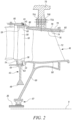
- FIG. 1 illustrates a gas turbine engine 10 having a principal rotational axis 9.
- the engine 10 comprises an air intake 12 and a propulsive fan 23 that generates two airflows: a core airflow A and a bypass airflow B.
- the gas turbine engine 10 comprises a core 11 that receives the core airflow A.
- the engine core 11 comprises, in axial flow series, a low pressure compressor 14, a high-pressure compressor 15, combustion equipment 16, a high-pressure turbine 17, a low pressure turbine 19 and a core exhaust nozzle 20.
- a nacelle 21 surrounds the gas turbine engine 10 and defines a bypass duct 22 and a bypass exhaust nozzle 18.
- the bypass airflow B flows through the bypass duct 22.
- the fan 23 is attached to and driven by the low pressure turbine 19 via a shaft 26 and an epicyclic gearbox 30.
- the core airflow A is accelerated and compressed by the low pressure compressor 14 and directed into the high pressure compressor 15 where further compression takes place.
- the compressed air exhausted from the high pressure compressor 15 is directed into the combustion equipment 16 where it is mixed with fuel and the mixture is combusted.
- the resultant hot combustion products then expand through, and thereby drive, the high pressure and low pressure turbines 17, 19 before being exhausted through the nozzle 20 to provide some propulsive thrust.
- the high pressure turbine 17 drives the high pressure compressor 15 by a suitable interconnecting shaft 27.
- the fan 23 generally provides the majority of the propulsive thrust.
- the epicyclic gearbox 30 is a reduction gearbox.
- low pressure turbine and “low pressure compressor” as used herein may be taken to mean the lowest pressure turbine stages and lowest pressure compressor stages (i.e. not including the fan 23) respectively and/or the turbine and compressor stages that are connected together by the interconnecting shaft 26 with the lowest rotational speed in the engine (i.e. not including the gearbox output shaft that drives the fan 23).
- the "low pressure turbine” and “low pressure compressor” referred to herein may alternatively be known as the "intermediate pressure turbine” and “intermediate pressure compressor”. Where such alternative nomenclature is used, the fan 23 may be referred to as a first, or lowest pressure, compression stage.
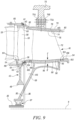
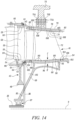
- the low pressure turbine 17 includes a turbine rotor arrangement 42, a turbine seal arrangement 44 and a turbine outlet stator vane arrangement 46, as shown in Figures 2 to 5 .
- the turbine rotor arrangement 42 comprises a rotor 48 and a plurality of circumferentially spaced turbine rotor blades 50 extending radially from and being secured to the rotor 48.
- Each turbine rotor blade 50 comprises a root 52, a shank, 54, a platform 56, an aerofoil 58 and a turbine shroud 60.
- the root 52 of each turbine rotor blade 50 locates in a slot 64 in the rim 62 of the rotor 48.
- the rotor 48 comprises one or more axially spaced discs secured together by fasteners or may comprise a unitary drum. In the case that the rotor 48 comprises a plurality of discs, each of the discs has a plurality of circumferentially spaced turbine rotor blades 50 extending radially from and being secured to the respective disc.
- the turbine seal arrangement 44 is spaced radially from and arranged around the turbine shrouds 60 of the turbine rotor blades 50.
- the turbine seal arrangement 44 is mounted onto a turbine casing 66.
- the turbine outlet stator vane arrangement 46 comprises a radially inner annular member 68, a radially outer annular member 70 arranged coaxially around the radially inner annular member 68 and a plurality of circumferentially spaced vanes 72 extending radially between and secured to the radially inner annular member 68 and the radially outer annular member 70.
- the coaxial arrangement may include some eccentricity and retain its functionality.
- the radially outer annular member 70 has a radially inner surface 74.
- the vanes 72 of the turbine outlet stator vane arrangement 46 are arranged downstream of the rotor blades 50 of the turbine rotor arrangement 42 and in particular are arranged downstream of the most downstream row of rotor blades 50 of the turbine rotor arrangement 42.
- the radially outer annular member 70 has at least one radially outwardly extending flange, or at least one radially outwardly extending lug 71, whereby in operation the at least one flange, or the at least one lug 71 is secured to an aircraft pylon 73 by at least one pin 73a.
- the radially outer annular member 70 may have a first radially outwardly extending flange 71A and a second radially outwardly extending flange 71B spaced axially from the first radially outwardly extending flange 71A, whereby in operation the flanges 71A and 71B are secured to the aircraft pylon 73.
- the flanges 71A and 71B may be connected to the aircraft pylon 73 at two circumferentially spaced points.
- the radially outer annular member 70 may have a first radially outwardly extending lug 71A and a second radially outwardly extending lug 71B spaced axially from the first radially outwardly extending lug 71A, whereby in operation the lugs 71A and 71B are secured to the aircraft pylon 73.
- the radially outer annular member 70 may have a first radially outwardly extending lug 71A and a second radially outwardly extending lug 71B spaced axially from the first radially outwardly extending lug 71A, a third radially outwardly extending lug (not shown) arranged in the same plane perpendicular to the rotational axis 9 as the first radially outwardly extending lug 71A but spaced circumferentially from the first radially outwardly extending lug 71A and a fourth radially outwardly extending lug (not shown) arranged in the same plane perpendicular to the rotational axis 9 as the second radially outwardly extending lug 71 B but spaced circumferentially from the second radially outwardly extending lug 71B, whereby in operation each of the first, second, third and fourth lugs are secured to the aircraft pylon 73.
- a support structure 69 extends radially inwardly from the radially inner annular member 68 and the support structure 69 supports a bearing 67.
- the rotor 48 is connected to the shaft 26.
- the bearing 67 rotatably mounts the rotor 48 of the turbine rotor arrangement 42 and in particular the bearing 67 rotatably mounts a downstream end of the shaft 26.
- the shaft 26 connects the low pressure turbine 17 to the intermediate pressure compressor 14 and connects the low pressure turbine 17 to the sun gear 28 of the epicyclic gearbox 30.
- the bearing 67 may be a roller bearing or a ball bearing.
- a liner 76 is spaced radially inwardly from the radially inner surface 74 of the radially outer annular member 70 to define a chamber 78 which has an inlet 80 at an upstream end of the liner 76 and an outlet 82 at a downstream end of the liner 76.
- the turbine shrouds 60 and the upstream end of the liner 76 are arranged relative to each other such that in operation any leakage flow of gas between the turbine shrouds 60 and the turbine seal arrangement 44 flows into the chamber 78 between the radially inner surface 74 of the radially outer annular member 70 and the liner 76 to manage the temperature of the radially outer annular member 70.
- the turbine shrouds 60 have radially outwardly extending fins 61 which form a seal with the turbine seal arrangement 44.
- the turbine seal arrangement 44 for example comprises a honeycomb structure 45, bonded to a solid backing member 47 and the fins 61 of the turbine shrouds 60 are arranged to rub against the honeycomb structure 45 or form a small clearance with the honeycomb structure 45.
- the turbine seal arrangement 44 comprises an abradable material 45 bonded to a solid backing member 47 and the fins 61 of the turbine shrouds 60 are arranged to rub against the abradable material 45 or form a small clearance with the abradable material 45.
- a radially inner surface 59 at the downstream ends of the turbine shrouds 60 is arranged at a first radius R1, the turbine seal arrangement 44 is arranged at a second radius R2, the liner 76 has a radially outer surface 84 and the radially outer surface 84 at the upstream end of the liner 76 is arranged at a third radius R3 wherein the third radius R3 is equal to or greater than the first radius R1 and less than the second radius R2, as shown in Figure 3 .
- a radially outer surface 63 at the downstream ends of the turbine shrouds 60 is arranged at a fourth radius R4.
- the third radius R3 may be equal to or greater than the fourth radius R4.
- the radii R1, R2, R3 and R4 are measured relative to the rotational axis 9.
- the radially outer annular member 70 has a plurality of radially inwardly extending hooks 86 and the liner 76 has a plurality of radially outwardly extending hooks 88 to engage the radially inwardly extending hooks 86 on the radially outer annular member 70.
- the radially outer annular member 70 has a first annular radially inwardly extending hook 86A and a second annular radially inwardly extending hook 86B spaced axially from the first annular radially inwardly extending hook 86A.
- the liner 76 has a first plurality of circumferentially spaced radially outwardly extending hooks 88A and a second plurality of circumferentially spaced radially outwardly extending hooks 88B spaced axially from the first plurality of circumferentially spaced radially outwardly extending hooks 88A.
- the liner 76 comprises a plurality of circumferentially arranged liner panels 75. Each liner panel 75 has circumferentially spaced edges 77 and the circumferentially spaced edges 77 are shaped to correspond to the shape of the vanes 72.
- Each liner panel 75 has at least one radially outwardly extending hook 88A at an upstream end and at least one radially outwardly extending hook 88B at a downstream end.
- Each liner panel 75 may have two circumferentially spaced radially outwardly extending hooks 88A at an upstream end and two circumferentially spaced radially outwardly extending hooks 88B at the downstream end.
- the radially outer annular member 70 may engage with the liner 76 in a manner that does not involve the use of hooks i.e. they may be engageable using an alternative arrangement, for example using flanges and bolted joints and the like.
- the upstream end of the liner 76 curves radially outwardly such that the radially inner surface of the liner 76 and the radially outer surface of the liner 76 curve radially outwardly in an upstream direction.
- the downstream end of the liner 76 curves radially inwardly such that the radially inner surface of the liner 76 and the radially outer surface of the liner 76 curve radially inwardly in a downstream direction. This curvature of the downstream end of the liner 76 enables the flow of hot exhaust gases exiting the chamber 78 to return to the flowpath through the gas turbine engine 10 downstream of the vanes 72 in an aerodynamically efficient manner.
- the over tip leakage flow of hot exhaust gases G between the turbine shrouds 60 and the turbine seal arrangement 44 flows into the chamber 78 between the radially inner surface 74 of the radially outer annular member 70 and the liner 76 to manage the temperature of the radially outer annular member 70.
- the hot exhaust gases H flowing between the turbine shrouds 60 and the turbine seal arrangement 44 is hotter than the mean exit temperature of the hot exhaust gases that have passed between and over the surfaces of the aerofoils 58 of the last stage of turbine blades 50 as the flow of hot exhaust gases in the over tip leakage flow do not have any work extracted from it.
- these hot exhaust gases H have greater thermal potential for heating the radially outer annular member 70 and these hot exhaust gases are ducted in close proximity to the radially inner surface 74 of the radially outer annular member 70.
- the liner 76 defines a duct to direct these hot exhaust gases H into close proximity to the radially inner surface 74 of the radially outer annular member 70.
- the hot exhaust gases I leaving the chamber 78 are directed in a controlled way into the flowpath through the gas turbine engine 10 downstream of the vanes 72 of the turbine outlet stator vane arrangement 46 and reduce pressure losses in the flow between the vanes 72 of the turbine outlet stator vane arrangement 46 and hence reduce specific fuel consumption of the gas turbine engine 10.
- the hot exhaust gases in the over tip leakage flow normally mix back into the a flowpath through the gas turbine engine in an uncontrolled way upstream of the vanes of the turbine outlet stator vane arrangement, produce an increase in pressure loss in the flow between the vanes of the turbine outlet guide vanes and hence increase specific fuel consumption.
- the heat provided by the hot exhaust gases flowing through the chamber 78 heats the radially outer annular member 70 and causes the radially outer annular member 70 to expand radially outwardly and/or increases the rate at which the radially outer annular member 70 expands radially outwardly and hence reduces the stresses on the turbine outlet stator vane arrangement 46 with a consequential increase in the low cycle fatigue life of the turbine outlet stator vane arrangement 46.
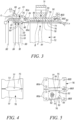
- the radially inner surface 74 of the radially outer annular member 70 has at least one heat transfer augmentation feature 90 extending radially inwardly therefrom, as shown in Figure 3 .
- the at least one heat transfer augmentation feature 90 is arranged axially between the first annular radially inwardly extending hook 86A and the second annular radially inwardly extending hook 86B.
- the radially inner surface 74 of the radially outer annular member 70 may have at least one circumferentially extending rib extending radially inwardly therefrom.
- the radially inner surface 74 of the radially outer annular member 70 may have a plurality of axially spaced circumferentially extending ribs extending radially inwardly therefrom.
- One or more of the ribs may an annular rib.
- The, or each, annular rib is positioned upstream of the leading edges of the vanes 72 or downstream of the trailing edges of the vanes 72.
- the ribs axially between the leading edges of the vanes and the trailing edges of the vanes 72 extend circumferentially between two adjacent vanes 72.
- the radially inner surface 74 of the radially outer annular member 70 may have a plurality of pedestals extending radially inwardly therefrom.
- the pedestals may be arranged in a plurality of axially spaced rows.
- the rib, the ribs and/or the pedestals form the heat transfer augmentation features.
- the radially outer surface 84 of the liner panels 75 do not have any heat transfer augmentation features as shown in the uppermost liner panel 75 in Figure 5 .
- the augmentation features, e.g. the ribs and/or pedestals, 90 shown in Figure 3 increase the transfer of heat into the radially outer annular member 70, e.g. increase the rate at which the radially outer annular member 70 heats up.
- the radially outer surface 84 of the liner panels 75 of the liner 76 may have at least one heat transfer augmentation feature 92 extending radially outwardly therefrom, as shown in the lowermost liner panel 75 in Figure 5 .
- the at least one heat transfer augmentation feature 92 is arranged between the first plurality of circumferentially spaced radially outwardly extending hooks 88A and the second plurality of circumferentially spaced radially outwardly extending hooks 88B.
- the radially outer surface 84 of the liner panels 75 of the liner 76 may have at least one circumferentially extending rib extending radially outwardly therefrom.
- the radially outer surface 84 of the liner panels 75 of the liner 76 may have a plurality of axially spaced circumferentially extending ribs extending radially outwardly therefrom.
- One or more of the ribs may an annular rib and in particular the circumferentially extending ribs on the circumferentially adjacent liner panels 75 are aligned to form an annular rib.
- The, or each, annular rib is positioned upstream of the leading edges of the vanes 72 or downstream of the trailing edges of the vanes 72.
- the ribs axially between the leading edges of the vanes and the trailing edges of the vanes 72 extend circumferentially between two adjacent vanes 72.
- the radially outer surface 84 of the liner panels 75 of the liner 76 may have a plurality of pedestals extending radially outwardly therefrom.
- the pedestals may be arranged in a plurality of axially spaced rows.
- the augmentation features, e.g. the ribs and/or pedestals, 92 shown in Figure 3 increase the transfer of heat into the radially outer annular member 70, e.g. increase the rate at which the radially outer annular member 70 heats up.
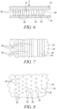
- Figure 6 shows an arrangement in which the radially inner surface 74 of the radially outer annular member 70 has at least one heat transfer augmentation feature 90 extending radially inwardly therefrom and the radially outer surface 84 of the liner panels 75 of the liner 76 may have at least one heat transfer augmentation feature 92 extending radially outwardly therefrom.
- Figure 7 shows an arrangement in which ribs on the radially inner surface 74 of the radially outer annular member 70 are arranged axially alternately with ribs on the radially outer surface 84 of the liner panels 75 of the liner 76.
- Figure 8 shows an arrangement in which rows of pedestals on the radially inner surface 74 of the radially outer annular member 70 are arranged axially alternately with rows of pedestals on the radially outer surface 84 of the liner panels 75 of the liner 76.
- the pedestals in the rows of pedestals on the radially inner surface 74 of the radially outer annular member 70 are staggered circumferentially with respect to the pedestals in the rows of pedestals on the liner panels 75 of the liner 76.
- the augmentation features, e.g. the ribs and/or pedestals, 92 shown in Figure 3 increase the transfer of heat into the radially outer annular member 70, e.g. increase the rate at which the radially outer annular member 70 heats up.
- ribs on the radially inner surface of the radially outer annular member may be arranged axially alternately with rows of pedestals on the outer surface of the liner.
- rows of pedestals on the radially inner surface of the radially outer annular member may be arranged axially alternately with ribs on the radially outer surface of the liner.
- the chamber defined between the liner and the radially outer annular member allows the flow of relatively hot exhaust gases flowing through the gap between the turbine shrouds and the turbine seal arrangement to manage the temperature of the radially outer annular member and the augmentation features maximise heat transfer into the radially outer member such that the radially outer annular member more closely matches the expansion of the vanes and hence reduces stress levels.
- the liner may also contribute to turbine blade containment which enables the thickness of the radially outer annular member to be reduced and hence reduce the mass and the stiffness of the radially outer annular member and enable the radially outer annular member to heat up more rapidly and therefore reduce thermal fatigue stress.
- FIG. 9 to 11 An alternative arrangement of the low pressure turbine 17 is shown in Figures 9 to 11 and also includes a turbine rotor arrangement 42, a turbine seal arrangement 44 and a turbine outlet stator vane arrangement 46.
- the arrangement of Figures 9 to 11 is substantially the same as that shown in Figures 2 to 5 , and like parts are denoted by like numbers.
- Figures 9 to 11 differ from the arrangement of Figures 2 to 5 in that a second liner 94 is spaced radially outwardly from the radially outer surface 96 of the radially inner annular member 68 to define a second chamber 98 which has an inlet 100 at an upstream end of the liner 94 and an outlet 102 at a downstream end of the second liner 94.
- the turbine rotor blades 50 and the upstream end of the second liner 94 are arranged relative to each other such that in operation coolant which has flowed through internal coolant passages within the turbine rotor blades 50 flows into the second chamber 98 between the radially outer surface 74 of the radially inner annular member 68 and the second liner 94.
- the coolant may heat the radially inner annular member 68 if it is hotter than the radially inner annular member 68 or cool the radially inner annular member 68 if it is hotter than the radially inner annular member 68.
- the turbine rotor blades 50 are provided with coolant passage exits arranged radially below the platforms 56 of the turbine rotor blades 50 and at the downstream ends of the turbine rotor blades 50 coolant which has flowed through internal coolant passages within the turbine rotor blades 50 flows into the second chamber 98 between the radially outer surface 74 of the radially inner annular member 68 and the second liner 94 to heat, or cool, the radially inner annular member 68.
- a radially outer surface 57 at the downstream ends of the platforms 56 of the turbine rotor blades 50 is arranged at a fifth radius R5
- the second liner 94 has a radially inner surface 93 and the radially inner surface 93 at the upstream end of the second liner 94 is arranged at a sixth radius R6, wherein the sixth radius R6 is equal to or less than the fifth radius R5.
- a radially inner surface 55 at the downstream ends of the platforms 56 of the turbine rotor blades 50 is arranged at a seventh radius R7 and the sixth radius R6 is equal to or less than the seventh radius R7.
- the radii R5, R6 and R7 are measured relative to the rotational axis 9.
- the radially inner annular member 68 has a plurality of radially outwardly extending hooks 104 and the second liner 94 has a plurality of radially inwardly extending hooks 106 to engage the radially inwardly extending hooks 104 on the radially inner annular member 68.
- the radially inner annular member 68 has a first annular radially outwardly extending hook 104 and a second annular radially outwardly extending hook 104 spaced axially from the first annular radially inwardly extending hook 104.
- the second liner 94 has a first plurality of circumferentially spaced radially inwardly extending hooks 106A and a second plurality of circumferentially spaced radially inwardly extending hooks 106B spaced axially from the first plurality of circumferentially spaced radially inwardly extending hooks 106A.
- the second liner 94 comprises a plurality of circumferentially arranged liner panels 95. Each liner panel 95 has circumferentially spaced edges 97 and the circumferentially spaced edges 97 are shaped to correspond to the shape of the vanes 72.
- Each liner panel 95 has at least one radially inwardly extending hook 106A at an upstream end and at least one radially inwardly extending hook 106B at a downstream end.
- Each liner panel 95 may have two circumferentially spaced radially inwardly extending hooks 106A at an upstream end and two circumferentially spaced radially inwardly extending hooks 106B at the downstream end.
- the radially inner annular member 68 and/or the second liner 94 may have heat transfer augmentation features as described with reference to those used on the radially outer annular member 70 and/or the liner 76, e.g. circumferentially extending ribs or rows of pedestals or circumferentially extending ribs and rows of pedestals.
- cooling air is supplied from a disc cavity 112 between a downstream face of the rotor 48 and an upstream face of the support structure 69 radially outwardly and then in a downstream direction into the second chamber 98 to cool the radially inner annular member 68.
- a further alternative is to provide apertures 114 in the platforms 56 of the turbine rotor blades 50 to connect the hot exhaust gases in the flow path through the turbine rotor blades 50 with spaces 116 radially underneath the platforms 56, radially above the disc posts of the rotor 48 and circumferentially between the shanks 54 of the turbine rotor blades 50 such that hot exhaust gas is able to flow radially inwardly into the spaces 116 and then in a downstream direction into the second chamber 98 to manage the temperature of the radially inner annular member 68.
- FIG. 12 An alternative arrangement of the low pressure turbine 17 is shown in Figure 12 and also includes a turbine rotor arrangement 42, a turbine seal arrangement 44 and a turbine outlet stator vane arrangement 46.
- the arrangement of Figure 12 is substantially the same as that shown in Figures 9 to 11 , and like parts are denoted by like numbers.
- the arrangement in Figure 12 differs in that the liner 76 and the second liner 94 are provided with apertures 108 and 110 respectively.
- the apertures 108 extend radially through the liner 76 and interconnect the chamber 78 and the gas in the flow path through the turbine outlet stator vane arrangement 46.
- the apertures 110 extend radially through the second liner 94 and interconnect the second chamber 98 and the gas in the flow path through the turbine outlet stator vane arrangement 46.
- the apertures 108 in the liner 76 and the apertures 110 in the second liner 94 allow gases to flow from the flow path through the turbine outlet stator vane arrangement 46 into the chamber 78 and the second chamber 98 respectively.
- the gas flowing through the apertures 108 into the chamber 78 reduces the heating effect of the over tip leakage flow of hot exhaust gases G between the turbine shrouds 60 and the turbine seal arrangement 44.
- the gas flowing through the apertures 110 into the second chamber 98 may reduce the heating effect of the cooling air flowing out of the turbine rotor blades 50, reduce the cooling effect of the cooling air flowing from the disc cavity 112 or reduce the heating effect of the hot gas which has flowed through the apertures 114 and the spaces 116.
- a fluid is supplied into the second chamber 98 to control the temperature of the radially inner annular member 68.
- Figure 13 shows an alternative arrangement of the low pressure turbine 17 shown in Figure 12 but only alternative in that there is a narrower inlet to the chamber that is defined by the liner and the radially inner surface of the radially outer annular member, i.e. the inlet is partially sealed.
- Figure 14 shows an alternative low pressure configuration where a static row of aerofoils 200 is positioned between the last blade and the turbine outlet static vane.
- Figure 15 shows an alternative liner configuration, featuring apertures 108 that enable the gas path flow heating the radially outer annular member 70 in a more efficient way by means of impingement, i.e. by having small apertures 108 fast moving jets of air will form that augment heat extraction by increasing the heat transfer coefficient.
- the present disclosure has referred to the radially outer annular member being secured to an aircraft pylon, or other aircraft structure, it is equally possible that the radially outer annular member is not secured to an aircraft pylon or aircraft structure.
- a support structure extending radially inwardly from the radially inner annular member to support a bearing
- a support structure is not provided extending radially inwardly from the radially inner annular member.
- a support structure that extends inwards but does not support a bearing.
Landscapes
- Engineering & Computer Science (AREA)
- Mechanical Engineering (AREA)
- General Engineering & Computer Science (AREA)
- Chemical & Material Sciences (AREA)
- Combustion & Propulsion (AREA)
- Turbine Rotor Nozzle Sealing (AREA)
Applications Claiming Priority (2)
| Application Number | Priority Date | Filing Date | Title |
|---|---|---|---|
| ES202131216 | 2021-12-24 | ||
| GB2201597.8A GB2615366A (en) | 2022-02-08 | 2022-02-08 | A turbine arrangement including a turbine outlet stator vane arrangement |
Publications (1)
| Publication Number | Publication Date |
|---|---|
| EP4202184A1 true EP4202184A1 (de) | 2023-06-28 |
Family
ID=84535985
Family Applications (1)
| Application Number | Title | Priority Date | Filing Date |
|---|---|---|---|
| EP22213343.1A Pending EP4202184A1 (de) | 2021-12-24 | 2022-12-14 | Gasturbine mit einer erhitzten turbinenauslassleitschaufelanordnung |
Country Status (4)
| Country | Link |
|---|---|
| US (1) | US12018573B2 (de) |
| EP (1) | EP4202184A1 (de) |
| CN (1) | CN116335772A (de) |
| CA (1) | CA3182646A1 (de) |
Families Citing this family (3)
| Publication number | Priority date | Publication date | Assignee | Title |
|---|---|---|---|---|
| EP4624726A1 (de) * | 2024-02-09 | 2025-10-01 | RTX Corporation | Gestapelte kompressorrotorscheiben mit thermischer konditionierungsbaugruppe |
| CN119801671B (zh) * | 2024-11-11 | 2025-12-26 | 中国航发沈阳发动机研究所 | 一种带封闭通道的涡轮间机匣放气结构 |
| CN119801989B (zh) * | 2025-03-13 | 2025-07-15 | 中国航发沈阳发动机研究所 | 一种可调整排气压力损失的节流装置 |
Citations (12)
| Publication number | Priority date | Publication date | Assignee | Title |
|---|---|---|---|---|
| US1493266A (en) * | 1922-12-05 | 1924-05-06 | Gen Electric | Elastic-fluid turbine |
| US3975901A (en) * | 1974-07-31 | 1976-08-24 | Societe Nationale D'etude Et De Construction De Moteurs D'aviation | Device for regulating turbine blade tip clearance |
| GB1581566A (en) * | 1976-08-02 | 1980-12-17 | Gen Electric | Minimum clearance turbomachine shroud apparatus |
| US4752185A (en) * | 1987-08-03 | 1988-06-21 | General Electric Company | Non-contacting flowpath seal |
| EP1052375A2 (de) * | 1999-05-14 | 2000-11-15 | General Electric Company | Einrichtung und Methode zur Verminderung von Wärmespannungen bei gekühlten Turbinenleitapparaten |
| EP1205634A2 (de) * | 2000-11-03 | 2002-05-15 | General Electric Company | Gasturbinenschaufelkühlung |
| US20090110550A1 (en) * | 2007-10-03 | 2009-04-30 | Kabushiki Kaisha Toshiba | Axial flow turbine and stage structure thereof |
| EP2116692A2 (de) * | 2008-05-07 | 2009-11-11 | Rolls-Royce plc | Turbinenschaufelanordnung |
| US20100226768A1 (en) * | 2009-03-03 | 2010-09-09 | Hitachi, Ltd. | Axial-flow turbine |
| JPWO2013027239A1 (ja) * | 2011-08-24 | 2015-03-05 | 三菱日立パワーシステムズ株式会社 | 軸流タービン |
| EP2889456A1 (de) * | 2012-07-11 | 2015-07-01 | Mitsubishi Hitachi Power Systems, Ltd. | Axial durchströmte abgasturbine |
| EP3098391A2 (de) * | 2015-05-07 | 2016-11-30 | General Electric Company | Flansche zur verhinderung der turbinenbandakkordeonbildung |
Family Cites Families (11)
| Publication number | Priority date | Publication date | Assignee | Title |
|---|---|---|---|---|
| FR2635562B1 (fr) * | 1988-08-18 | 1993-12-24 | Snecma | Anneau de stator de turbine associe a un support de liaison au carter de turbine |
| US6779597B2 (en) * | 2002-01-16 | 2004-08-24 | General Electric Company | Multiple impingement cooled structure |
| US7063509B2 (en) * | 2003-09-05 | 2006-06-20 | General Electric Company | Conical tip shroud fillet for a turbine bucket |
| US20060280610A1 (en) * | 2005-06-13 | 2006-12-14 | Heyward John P | Turbine blade and method of fabricating same |
| US20130230379A1 (en) * | 2012-03-01 | 2013-09-05 | General Electric Company | Rotating turbomachine component having a tip leakage flow guide |
| ES2700788T3 (es) * | 2012-04-04 | 2019-02-19 | MTU Aero Engines AG | Sistema de sellado para una turbomáquina |
| US9238977B2 (en) * | 2012-11-21 | 2016-01-19 | General Electric Company | Turbine shroud mounting and sealing arrangement |
| EP3012409B1 (de) | 2014-10-22 | 2020-04-29 | General Electric Technology GmbH | Turbinenanordnung |
| GB201519869D0 (en) * | 2015-11-11 | 2015-12-23 | Rolls Royce Plc | Shrouded turbine blade |
| EP3358142B1 (de) | 2017-02-02 | 2021-08-18 | General Electric Company | Kontrolle der spaltleckage über ein turbinenschaufeldeckband |
| JP7380846B2 (ja) * | 2020-03-30 | 2023-11-15 | 株式会社Ihi | 二次流れ抑制構造 |
-
2022
- 2022-11-23 CA CA3182646A patent/CA3182646A1/en active Pending
- 2022-12-12 US US18/079,133 patent/US12018573B2/en active Active
- 2022-12-14 EP EP22213343.1A patent/EP4202184A1/de active Pending
- 2022-12-23 CN CN202211670641.9A patent/CN116335772A/zh active Pending
Patent Citations (12)
| Publication number | Priority date | Publication date | Assignee | Title |
|---|---|---|---|---|
| US1493266A (en) * | 1922-12-05 | 1924-05-06 | Gen Electric | Elastic-fluid turbine |
| US3975901A (en) * | 1974-07-31 | 1976-08-24 | Societe Nationale D'etude Et De Construction De Moteurs D'aviation | Device for regulating turbine blade tip clearance |
| GB1581566A (en) * | 1976-08-02 | 1980-12-17 | Gen Electric | Minimum clearance turbomachine shroud apparatus |
| US4752185A (en) * | 1987-08-03 | 1988-06-21 | General Electric Company | Non-contacting flowpath seal |
| EP1052375A2 (de) * | 1999-05-14 | 2000-11-15 | General Electric Company | Einrichtung und Methode zur Verminderung von Wärmespannungen bei gekühlten Turbinenleitapparaten |
| EP1205634A2 (de) * | 2000-11-03 | 2002-05-15 | General Electric Company | Gasturbinenschaufelkühlung |
| US20090110550A1 (en) * | 2007-10-03 | 2009-04-30 | Kabushiki Kaisha Toshiba | Axial flow turbine and stage structure thereof |
| EP2116692A2 (de) * | 2008-05-07 | 2009-11-11 | Rolls-Royce plc | Turbinenschaufelanordnung |
| US20100226768A1 (en) * | 2009-03-03 | 2010-09-09 | Hitachi, Ltd. | Axial-flow turbine |
| JPWO2013027239A1 (ja) * | 2011-08-24 | 2015-03-05 | 三菱日立パワーシステムズ株式会社 | 軸流タービン |
| EP2889456A1 (de) * | 2012-07-11 | 2015-07-01 | Mitsubishi Hitachi Power Systems, Ltd. | Axial durchströmte abgasturbine |
| EP3098391A2 (de) * | 2015-05-07 | 2016-11-30 | General Electric Company | Flansche zur verhinderung der turbinenbandakkordeonbildung |
Also Published As
| Publication number | Publication date |
|---|---|
| US20230296032A1 (en) | 2023-09-21 |
| US12018573B2 (en) | 2024-06-25 |
| CN116335772A (zh) | 2023-06-27 |
| CA3182646A1 (en) | 2023-06-24 |
Similar Documents
| Publication | Publication Date | Title |
|---|---|---|
| US12018573B2 (en) | Turbine arrangement including a turbine outlet stator vane arrangement | |
| EP1921255B1 (de) | Turbinenmotor mit Zwischenkühlung | |
| US6902371B2 (en) | Internal low pressure turbine case cooling | |
| EP1921292B1 (de) | Verbundtriebwerk mit Turbinenkühlung | |
| US9976433B2 (en) | Gas turbine engine with non-axisymmetric surface contoured rotor blade platform | |
| US8356975B2 (en) | Gas turbine engine with non-axisymmetric surface contoured vane platform | |
| US10718265B2 (en) | Interdigitated turbine engine air bearing and method of operation | |
| US10605168B2 (en) | Interdigitated turbine engine air bearing cooling structure and method of thermal management | |
| US10669893B2 (en) | Air bearing and thermal management nozzle arrangement for interdigitated turbine engine | |
| US10876407B2 (en) | Thermal structure for outer diameter mounted turbine blades | |
| US10787931B2 (en) | Method and structure of interdigitated turbine engine thermal management | |
| US20230184165A1 (en) | Vane assembly for a gas turbine engine | |
| US12055153B1 (en) | Variable pitch airfoil assembly for an open fan rotor of an engine having a damping element | |
| EP4386193B1 (de) | Wärmeverwaltungssystem für gasturbinenmotor | |
| GB2615366A (en) | A turbine arrangement including a turbine outlet stator vane arrangement | |
| US20250198290A1 (en) | Gas turbine engine | |
| US11156110B1 (en) | Rotor assembly for a turbine section of a gas turbine engine | |
| EP4474706B1 (de) | Brennkammeranordnung für einen gasturbinenmotor | |
| US12460557B1 (en) | Variable pitch airfoil assembly for a gas turbine engine | |
| US20200025093A1 (en) | Gas turbine engine heatshield | |
| US20250257687A1 (en) | Gas turbine engine | |
| US20250383089A1 (en) | Cooling ring for combustor system | |
| SAUNDERS | Advanced component technologies for energy-efficient turbofan engines | |
| Day | C56-50A Engines |
Legal Events
| Date | Code | Title | Description |
|---|---|---|---|
| PUAI | Public reference made under article 153(3) epc to a published international application that has entered the european phase |
Free format text: ORIGINAL CODE: 0009012 |
|
| STAA | Information on the status of an ep patent application or granted ep patent |
Free format text: STATUS: THE APPLICATION HAS BEEN PUBLISHED |
|
| AK | Designated contracting states |
Kind code of ref document: A1 Designated state(s): AL AT BE BG CH CY CZ DE DK EE ES FI FR GB GR HR HU IE IS IT LI LT LU LV MC ME MK MT NL NO PL PT RO RS SE SI SK SM TR |
|
| STAA | Information on the status of an ep patent application or granted ep patent |
Free format text: STATUS: REQUEST FOR EXAMINATION WAS MADE |
|
| 17P | Request for examination filed |
Effective date: 20231226 |
|
| RBV | Designated contracting states (corrected) |
Designated state(s): AL AT BE BG CH CY CZ DE DK EE ES FI FR GB GR HR HU IE IS IT LI LT LU LV MC ME MK MT NL NO PL PT RO RS SE SI SK SM TR |
|
| STAA | Information on the status of an ep patent application or granted ep patent |
Free format text: STATUS: EXAMINATION IS IN PROGRESS |
|
| 17Q | First examination report despatched |
Effective date: 20250530 |