EP4202242B1 - Kugellager - Google Patents
Kugellager Download PDFInfo
- Publication number
- EP4202242B1 EP4202242B1 EP21858204.7A EP21858204A EP4202242B1 EP 4202242 B1 EP4202242 B1 EP 4202242B1 EP 21858204 A EP21858204 A EP 21858204A EP 4202242 B1 EP4202242 B1 EP 4202242B1
- Authority
- EP
- European Patent Office
- Prior art keywords
- cage
- axial
- sliding contact
- ball bearing
- balls
- Prior art date
- Legal status (The legal status is an assumption and is not a legal conclusion. Google has not performed a legal analysis and makes no representation as to the accuracy of the status listed.)
- Active
Links
Images


Classifications
-
- F—MECHANICAL ENGINEERING; LIGHTING; HEATING; WEAPONS; BLASTING
- F16—ENGINEERING ELEMENTS AND UNITS; GENERAL MEASURES FOR PRODUCING AND MAINTAINING EFFECTIVE FUNCTIONING OF MACHINES OR INSTALLATIONS; THERMAL INSULATION IN GENERAL
- F16J—PISTONS; CYLINDERS; SEALINGS
- F16J15/00—Sealings
- F16J15/16—Sealings between relatively-moving surfaces
- F16J15/32—Sealings between relatively-moving surfaces with elastic sealings, e.g. O-rings
- F16J15/3204—Sealings between relatively-moving surfaces with elastic sealings, e.g. O-rings with at least one lip
- F16J15/3216—Sealings between relatively-moving surfaces with elastic sealings, e.g. O-rings with at least one lip supported in a direction parallel to the surfaces
-
- F—MECHANICAL ENGINEERING; LIGHTING; HEATING; WEAPONS; BLASTING
- F16—ENGINEERING ELEMENTS AND UNITS; GENERAL MEASURES FOR PRODUCING AND MAINTAINING EFFECTIVE FUNCTIONING OF MACHINES OR INSTALLATIONS; THERMAL INSULATION IN GENERAL
- F16C—SHAFTS; FLEXIBLE SHAFTS; ELEMENTS OR CRANKSHAFT MECHANISMS; ROTARY BODIES OTHER THAN GEARING ELEMENTS; BEARINGS
- F16C33/00—Parts of bearings; Special methods for making bearings or parts thereof
- F16C33/30—Parts of ball or roller bearings
- F16C33/38—Ball cages
- F16C33/3806—Details of interaction of cage and race, e.g. retention, centring
-
- F—MECHANICAL ENGINEERING; LIGHTING; HEATING; WEAPONS; BLASTING
- F16—ENGINEERING ELEMENTS AND UNITS; GENERAL MEASURES FOR PRODUCING AND MAINTAINING EFFECTIVE FUNCTIONING OF MACHINES OR INSTALLATIONS; THERMAL INSULATION IN GENERAL
- F16C—SHAFTS; FLEXIBLE SHAFTS; ELEMENTS OR CRANKSHAFT MECHANISMS; ROTARY BODIES OTHER THAN GEARING ELEMENTS; BEARINGS
- F16C33/00—Parts of bearings; Special methods for making bearings or parts thereof
- F16C33/30—Parts of ball or roller bearings
- F16C33/38—Ball cages
- F16C33/3837—Massive or moulded cages having cage pockets surrounding the balls, e.g. machined window cages
- F16C33/3843—Massive or moulded cages having cage pockets surrounding the balls, e.g. machined window cages formed as one-piece cages, i.e. monoblock cages
- F16C33/3856—Massive or moulded cages having cage pockets surrounding the balls, e.g. machined window cages formed as one-piece cages, i.e. monoblock cages made from plastic, e.g. injection moulded window cages
-
- F—MECHANICAL ENGINEERING; LIGHTING; HEATING; WEAPONS; BLASTING
- F16—ENGINEERING ELEMENTS AND UNITS; GENERAL MEASURES FOR PRODUCING AND MAINTAINING EFFECTIVE FUNCTIONING OF MACHINES OR INSTALLATIONS; THERMAL INSULATION IN GENERAL
- F16C—SHAFTS; FLEXIBLE SHAFTS; ELEMENTS OR CRANKSHAFT MECHANISMS; ROTARY BODIES OTHER THAN GEARING ELEMENTS; BEARINGS
- F16C33/00—Parts of bearings; Special methods for making bearings or parts thereof
- F16C33/30—Parts of ball or roller bearings
- F16C33/38—Ball cages
- F16C33/3887—Details of individual pockets, e.g. shape or ball retaining means
-
- F—MECHANICAL ENGINEERING; LIGHTING; HEATING; WEAPONS; BLASTING
- F16—ENGINEERING ELEMENTS AND UNITS; GENERAL MEASURES FOR PRODUCING AND MAINTAINING EFFECTIVE FUNCTIONING OF MACHINES OR INSTALLATIONS; THERMAL INSULATION IN GENERAL
- F16C—SHAFTS; FLEXIBLE SHAFTS; ELEMENTS OR CRANKSHAFT MECHANISMS; ROTARY BODIES OTHER THAN GEARING ELEMENTS; BEARINGS
- F16C33/00—Parts of bearings; Special methods for making bearings or parts thereof
- F16C33/30—Parts of ball or roller bearings
- F16C33/38—Ball cages
- F16C33/41—Ball cages comb-shaped
- F16C33/412—Massive or moulded comb cages, e.g. snap ball cages
- F16C33/414—Massive or moulded comb cages, e.g. snap ball cages formed as one-piece cages, i.e. monoblock comb cages
- F16C33/416—Massive or moulded comb cages, e.g. snap ball cages formed as one-piece cages, i.e. monoblock comb cages made from plastic, e.g. injection moulded comb cages
-
- F—MECHANICAL ENGINEERING; LIGHTING; HEATING; WEAPONS; BLASTING
- F16—ENGINEERING ELEMENTS AND UNITS; GENERAL MEASURES FOR PRODUCING AND MAINTAINING EFFECTIVE FUNCTIONING OF MACHINES OR INSTALLATIONS; THERMAL INSULATION IN GENERAL
- F16C—SHAFTS; FLEXIBLE SHAFTS; ELEMENTS OR CRANKSHAFT MECHANISMS; ROTARY BODIES OTHER THAN GEARING ELEMENTS; BEARINGS
- F16C33/00—Parts of bearings; Special methods for making bearings or parts thereof
- F16C33/30—Parts of ball or roller bearings
- F16C33/38—Ball cages
- F16C33/41—Ball cages comb-shaped
- F16C33/418—Details of individual pockets, e.g. shape or ball retaining means
-
- F—MECHANICAL ENGINEERING; LIGHTING; HEATING; WEAPONS; BLASTING
- F16—ENGINEERING ELEMENTS AND UNITS; GENERAL MEASURES FOR PRODUCING AND MAINTAINING EFFECTIVE FUNCTIONING OF MACHINES OR INSTALLATIONS; THERMAL INSULATION IN GENERAL
- F16C—SHAFTS; FLEXIBLE SHAFTS; ELEMENTS OR CRANKSHAFT MECHANISMS; ROTARY BODIES OTHER THAN GEARING ELEMENTS; BEARINGS
- F16C33/00—Parts of bearings; Special methods for making bearings or parts thereof
- F16C33/30—Parts of ball or roller bearings
- F16C33/66—Special parts or details in view of lubrication
- F16C33/6603—Special parts or details in view of lubrication with grease as lubricant
- F16C33/6607—Retaining the grease in or near the bearing
-
- F—MECHANICAL ENGINEERING; LIGHTING; HEATING; WEAPONS; BLASTING
- F16—ENGINEERING ELEMENTS AND UNITS; GENERAL MEASURES FOR PRODUCING AND MAINTAINING EFFECTIVE FUNCTIONING OF MACHINES OR INSTALLATIONS; THERMAL INSULATION IN GENERAL
- F16C—SHAFTS; FLEXIBLE SHAFTS; ELEMENTS OR CRANKSHAFT MECHANISMS; ROTARY BODIES OTHER THAN GEARING ELEMENTS; BEARINGS
- F16C33/00—Parts of bearings; Special methods for making bearings or parts thereof
- F16C33/30—Parts of ball or roller bearings
- F16C33/66—Special parts or details in view of lubrication
- F16C33/6637—Special parts or details in view of lubrication with liquid lubricant
- F16C33/664—Retaining the liquid in or near the bearing
- F16C33/6651—Retaining the liquid in or near the bearing in recesses or cavities provided in retainers, races or rolling elements
-
- F—MECHANICAL ENGINEERING; LIGHTING; HEATING; WEAPONS; BLASTING
- F16—ENGINEERING ELEMENTS AND UNITS; GENERAL MEASURES FOR PRODUCING AND MAINTAINING EFFECTIVE FUNCTIONING OF MACHINES OR INSTALLATIONS; THERMAL INSULATION IN GENERAL
- F16C—SHAFTS; FLEXIBLE SHAFTS; ELEMENTS OR CRANKSHAFT MECHANISMS; ROTARY BODIES OTHER THAN GEARING ELEMENTS; BEARINGS
- F16C33/00—Parts of bearings; Special methods for making bearings or parts thereof
- F16C33/30—Parts of ball or roller bearings
- F16C33/66—Special parts or details in view of lubrication
- F16C33/6637—Special parts or details in view of lubrication with liquid lubricant
- F16C33/6681—Details of distribution or circulation inside the bearing, e.g. grooves on the cage or passages in the rolling elements
-
- F—MECHANICAL ENGINEERING; LIGHTING; HEATING; WEAPONS; BLASTING
- F16—ENGINEERING ELEMENTS AND UNITS; GENERAL MEASURES FOR PRODUCING AND MAINTAINING EFFECTIVE FUNCTIONING OF MACHINES OR INSTALLATIONS; THERMAL INSULATION IN GENERAL
- F16C—SHAFTS; FLEXIBLE SHAFTS; ELEMENTS OR CRANKSHAFT MECHANISMS; ROTARY BODIES OTHER THAN GEARING ELEMENTS; BEARINGS
- F16C33/00—Parts of bearings; Special methods for making bearings or parts thereof
- F16C33/72—Sealings
- F16C33/76—Sealings of ball or roller bearings
- F16C33/78—Sealings of ball or roller bearings with a diaphragm, disc, or ring, with or without resilient members
- F16C33/7816—Details of the sealing or parts thereof, e.g. geometry, material
- F16C33/782—Details of the sealing or parts thereof, e.g. geometry, material of the sealing region
- F16C33/7826—Details of the sealing or parts thereof, e.g. geometry, material of the sealing region of the opposing surface cooperating with the seal, e.g. a shoulder surface of a bearing ring
-
- F—MECHANICAL ENGINEERING; LIGHTING; HEATING; WEAPONS; BLASTING
- F16—ENGINEERING ELEMENTS AND UNITS; GENERAL MEASURES FOR PRODUCING AND MAINTAINING EFFECTIVE FUNCTIONING OF MACHINES OR INSTALLATIONS; THERMAL INSULATION IN GENERAL
- F16J—PISTONS; CYLINDERS; SEALINGS
- F16J15/00—Sealings
- F16J15/16—Sealings between relatively-moving surfaces
- F16J15/32—Sealings between relatively-moving surfaces with elastic sealings, e.g. O-rings
- F16J15/324—Arrangements for lubrication or cooling of the sealing itself
-
- F—MECHANICAL ENGINEERING; LIGHTING; HEATING; WEAPONS; BLASTING
- F16—ENGINEERING ELEMENTS AND UNITS; GENERAL MEASURES FOR PRODUCING AND MAINTAINING EFFECTIVE FUNCTIONING OF MACHINES OR INSTALLATIONS; THERMAL INSULATION IN GENERAL
- F16C—SHAFTS; FLEXIBLE SHAFTS; ELEMENTS OR CRANKSHAFT MECHANISMS; ROTARY BODIES OTHER THAN GEARING ELEMENTS; BEARINGS
- F16C19/00—Bearings with rolling contact, for exclusively rotary movement
- F16C19/02—Bearings with rolling contact, for exclusively rotary movement with bearing balls essentially of the same size in one or more circular rows
- F16C19/04—Bearings with rolling contact, for exclusively rotary movement with bearing balls essentially of the same size in one or more circular rows for radial load mainly
- F16C19/06—Bearings with rolling contact, for exclusively rotary movement with bearing balls essentially of the same size in one or more circular rows for radial load mainly with a single row or balls
-
- F—MECHANICAL ENGINEERING; LIGHTING; HEATING; WEAPONS; BLASTING
- F16—ENGINEERING ELEMENTS AND UNITS; GENERAL MEASURES FOR PRODUCING AND MAINTAINING EFFECTIVE FUNCTIONING OF MACHINES OR INSTALLATIONS; THERMAL INSULATION IN GENERAL
- F16C—SHAFTS; FLEXIBLE SHAFTS; ELEMENTS OR CRANKSHAFT MECHANISMS; ROTARY BODIES OTHER THAN GEARING ELEMENTS; BEARINGS
- F16C2300/00—Application independent of particular apparatuses
- F16C2300/20—Application independent of particular apparatuses related to type of movement
- F16C2300/22—High-speed rotation
-
- F—MECHANICAL ENGINEERING; LIGHTING; HEATING; WEAPONS; BLASTING
- F16—ENGINEERING ELEMENTS AND UNITS; GENERAL MEASURES FOR PRODUCING AND MAINTAINING EFFECTIVE FUNCTIONING OF MACHINES OR INSTALLATIONS; THERMAL INSULATION IN GENERAL
- F16C—SHAFTS; FLEXIBLE SHAFTS; ELEMENTS OR CRANKSHAFT MECHANISMS; ROTARY BODIES OTHER THAN GEARING ELEMENTS; BEARINGS
- F16C2326/00—Articles relating to transporting
- F16C2326/01—Parts of vehicles in general
-
- F—MECHANICAL ENGINEERING; LIGHTING; HEATING; WEAPONS; BLASTING
- F16—ENGINEERING ELEMENTS AND UNITS; GENERAL MEASURES FOR PRODUCING AND MAINTAINING EFFECTIVE FUNCTIONING OF MACHINES OR INSTALLATIONS; THERMAL INSULATION IN GENERAL
- F16C—SHAFTS; FLEXIBLE SHAFTS; ELEMENTS OR CRANKSHAFT MECHANISMS; ROTARY BODIES OTHER THAN GEARING ELEMENTS; BEARINGS
- F16C2380/00—Electrical apparatus
- F16C2380/26—Dynamo-electric machines or combinations therewith, e.g. electro-motors and generators
-
- F—MECHANICAL ENGINEERING; LIGHTING; HEATING; WEAPONS; BLASTING
- F16—ENGINEERING ELEMENTS AND UNITS; GENERAL MEASURES FOR PRODUCING AND MAINTAINING EFFECTIVE FUNCTIONING OF MACHINES OR INSTALLATIONS; THERMAL INSULATION IN GENERAL
- F16C—SHAFTS; FLEXIBLE SHAFTS; ELEMENTS OR CRANKSHAFT MECHANISMS; ROTARY BODIES OTHER THAN GEARING ELEMENTS; BEARINGS
- F16C33/00—Parts of bearings; Special methods for making bearings or parts thereof
- F16C33/30—Parts of ball or roller bearings
- F16C33/38—Ball cages
- F16C33/44—Selection of substances
-
- F—MECHANICAL ENGINEERING; LIGHTING; HEATING; WEAPONS; BLASTING
- F16—ENGINEERING ELEMENTS AND UNITS; GENERAL MEASURES FOR PRODUCING AND MAINTAINING EFFECTIVE FUNCTIONING OF MACHINES OR INSTALLATIONS; THERMAL INSULATION IN GENERAL
- F16C—SHAFTS; FLEXIBLE SHAFTS; ELEMENTS OR CRANKSHAFT MECHANISMS; ROTARY BODIES OTHER THAN GEARING ELEMENTS; BEARINGS
- F16C33/00—Parts of bearings; Special methods for making bearings or parts thereof
- F16C33/72—Sealings
- F16C33/76—Sealings of ball or roller bearings
- F16C33/78—Sealings of ball or roller bearings with a diaphragm, disc, or ring, with or without resilient members
- F16C33/784—Sealings of ball or roller bearings with a diaphragm, disc, or ring, with or without resilient members mounted to a groove in the inner surface of the outer race and extending toward the inner race
- F16C33/7843—Sealings of ball or roller bearings with a diaphragm, disc, or ring, with or without resilient members mounted to a groove in the inner surface of the outer race and extending toward the inner race with a single annular sealing disc
- F16C33/7853—Sealings of ball or roller bearings with a diaphragm, disc, or ring, with or without resilient members mounted to a groove in the inner surface of the outer race and extending toward the inner race with a single annular sealing disc with one or more sealing lips to contact the inner race
- F16C33/7856—Sealings of ball or roller bearings with a diaphragm, disc, or ring, with or without resilient members mounted to a groove in the inner surface of the outer race and extending toward the inner race with a single annular sealing disc with one or more sealing lips to contact the inner race with a single sealing lip
Definitions
- Ball bearings are often used as bearings supporting rotary shafts of automobiles, industrial machines, etc.
- ball bearings include an inner ring; an outer ring arranged radially outwardly of, and coaxially with, the inner ring: a plurality of balls disposed in the annular space between the inner ring and the outer ring; and a cage retaining the balls.
- a sealed ball bearing as disclosed in the below-identified Patent Document 2 is sometimes used in which the axial end openings of the annular space between the inner ring and the outer ring are closed by annular seal members to prevent foreign matter from entering the ball bearing from the outside of the ball bearing, or to prevent a lubricant (such as lubricating oil or grease) from leaking from the interior of the ball bearing to the exterior.
- a lubricant such as lubricating oil or grease
- the inventors of the present application considered using a crown-shaped cage in a ball bearing supporting a rotary shaft of, e.g., an EV or a HEV that rotates at a high speed.
- the bearing using a crown-shaped cage is a sealed ball bearing with a seal member
- the axial width dimension of the cage circular annular portion needs to be reduced to prevent the cage circular annular portion from coming into contact with the seal member. Therefore, it is difficult to increase the rigidity of the cage circular annular portion. As a result, torsional deformation of the cage circular annular portion is likely to occur due to the centrifugal forces applied to the cage claw portions, and thus the cage claw portions are likely to interfere with the balls.
- each cage claw portion has an H-shaped cross section due to the outer-diameter-side axial groove in the radially outer surface of the cage claw portion and the inner-diameter-side axial groove in the radially inner surface of the cage claw portion, it is possible to reduce the mass of the cage claw portions while ensuring the moment of inertia of area of the cage claw portions (while making the cage claw portions less likely to deform against the bending moment). Therefore, even during high-speed rotation, it is possible to reduce torsional deformation of the cage circular annular portion, and flexural deformation of the cage claw portions per se toward the radially outer side due to the centrifugal forces which the cage claw portions receive.
- each of the cage claw portions has an axial length larger than a radius of each of the balls, and each of the cage claw portions has circumferentially opposed surfaces which are circumferentially opposed to the corresponding pair of the balls, respectively, and of which portions configured to circumferentially support the corresponding pair of the balls are flat surfaces extending such that when the cage claw portion is moved radially outwardly by a centrifugal force, the circumferentially opposed surfaces do not interfere with the corresponding pair of the balls.
- the cage circular annular portion has axially opposed surfaces axially opposed to the respective balls, and each of the circumferentially opposed surfaces of the cage claw portions is connected to a corresponding one of the axially opposed surfaces via a curved surface having a concave circular arc-shaped cross section.
- An axial end of the outer-diameter-side axial groove of each of the cage claw portions closer to the cage circular annular portion preferably rises to an outer periphery of the cage circular annular portion to form a concave circular arc-shaped cross section.
- the cage circular annular portion preferably has, on an inner periphery of the cage circular annular portion, a cage guided surface configured to be guided while coming into sliding contact with an outer periphery of the inner ring.
- Each of the axial protrusions preferably includes: a parallel apex portion having an axially convex circular arc-shape in cross sections along the circumferential direction whose apex height is radially uniform; and an inclined apex portion having an axially convex circular-arc shape in cross sections along the circumferential direction whose apex height gradually decreases radially outward from a radially outer end of the parallel apex portion.
- the inner-diameter-side axial groove of each of the cage claw portions is preferably shaped such that, from the distal end of the cage claw portion toward the cage circular annular portion, a position of a bottom of the inner-diameter-side axial groove gradually changes radially inwardly.
- an axial end of the annular space opposite from an axial end of the annular space closed by the seal member is not provided with an additional seal member, and is open so that lubricating oil supplied from outside enters the annular space through this opening.
- portions of the circumferentially opposed surfaces configured to circumferentially support the corresponding pair of the balls are preferably straight portions having no circumferential inclination, and extending straight in the axial direction so that when supporting the corresponding pair of the balls, no axial component forces are generated.
- the cage circular annular portion has, on an inner periphery of the cage circular annular portion, a cage guided surface configured to be guided while coming into sliding contact with an outer periphery of the inner ring
- the cage circular annular portion preferably has a chamfer obliquely extending in a cross section perpendicular to the circumferential direction, to connect the cage-side sliding contact surface and the cage guided surface to each other.
- each of the root-side guided surfaces has, in cross sections along the circumferential direction, a radially outwardly protruding circular arc shape, oil films due to the wedge film effect are formed between the one outer ring groove shoulder and the root-side guided surfaces. Due to the oil films, the lubrication condition between the one outer ring groove shoulder and the root-side guided surfaces becomes the fluid lubrication condition, thus making it possible to markedly reduce the contact resistance between the cage and the outer ring.
- the one outer ring groove shoulder supports the cage circular annular portion from the radially outer side
- the other outer ring groove shoulder supports the axial ends of the cage claw portions on their distal end sides from the radially outer side
- oil films due to the wedge film effect can be effectively formed between the one outer ring groove shoulder and the root-side guided surfaces, and oil films due to the wedge film effect can be effectively formed between the other outer ring groove shoulder and the distal-end-side guided surfaces, too.
- the present invention also provides a ball bearing comprising: an inner ring; an outer ring arranged radially outwardly of, and coaxially with, the inner ring; a plurality of balls disposed in an annular space between the inner ring and the outer ring; an annular seal member closing one axial end opening of the annular space; and a cage made of resin and retaining the balls, wherein the cage comprises a cage circular annular portion extending circumferentially through a space axially sandwiched between the seal member and the space through which the balls pass; and cage claw portions having a cantilevered structure extending from the cage circular annular portion, and each located between a corresponding pair of the balls circumferentially adjacent to each other, characterized in that the cage circular annular portion has a cage-side sliding contact surface axially opposed to the seal member and configured to come into sliding contact with the seal member, wherein the seal member has a seal-side sliding contact surface configured to come into sliding contact with the cage-side sliding contact surface, and
- the cage circular annular portion is disposed to come into sliding contact with the seal member, it is possible to increase the axial thickness of the cage circular annular portion, and thus increase the rigidity of the cage circular annular portion. Therefore, even during high-speed rotation, it is possible to reduce torsional deformation of the cage circular annular portion due to the centrifugal forces that the cage claw portions receive, and reduce inclination of the cage claw portions toward radially outer side.
- each of the cage claw portions has an axial length larger than a radius of each of the balls, and each of the cage claw portions has circumferentially opposed surfaces which are circumferentially opposed to the corresponding pair of the balls, respectively, and of which portions configured to circumferentially support the corresponding pair of the balls are straight portions having no circumferential inclination, and extending straight in an axial direction in order that when supporting the corresponding pair of the balls, no axial component forces are generated.
- the portions configured to circumferentially support the corresponding pair of the balls preferably extend parallel to an imaginary straight line connecting a center of the cage circular annular portion and a center of the cage claw portion to each other in order that when the cage claw portion is moved radially outwardly by a centrifugal force, the circumferentially opposed surfaces do not interfere with the corresponding pair of the balls.
- Each of the axial protrusions preferably includes: a parallel apex portion having an axially convex circular arc convex shape in cross sections along the circumferential direction whose apex height is radially uniform; and an inclined apex portion having an axially circular arc convex shape in cross sections along the circumferential direction whose apex height gradually decreases radially outward from a radially outer end of the parallel apex portion.
- a cross section of the inclined apex portion of each of the axial protrusions perpendicular to the circumferential direction preferably has a rounded shape smoothly connected to the parallel apex portion.
- the seal member comprises an annular metal core, and a rubber part bonded to a surface of the metal core by vulcanization, and the axial protrusions are formed of the same material as the rubber part.
- the cage made of resin can be radially positioned by the sliding contact between the cage guided surface of the cage circular annular portion on its inner periphery and the outer periphery of the inner ring.
- each of the root-side guided surfaces has, on a side thereof remoter from a corresponding one of the cage claw portions, an axial end edge chamfered into a rounded shape
- each of the distal-end-side guided surfaces has, on a side thereof remoter from the cage circular annular portion, an axial end edge chamfered into a rounded shape
- oil reservoir grooves If such oil reservoir grooves are formed, lubricating oil scattered radially outwardly by a centrifugal force can be stored in the oil reservoir grooves, and supplied to the inner ring.
- the axial protrusions are preferably disposed at positions where the axial protrusions overlap with a pitch circle of the balls, or disposed radially outwardly of the pitch circle.
- an axial end of the annular space opposite from an axial end of the annular space closed by the seal member is not provided with an additional seal member, and is open so that lubricating oil supplied from outside enters the annular space through this opening.
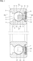
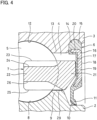
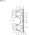
- Fig. 1 illustrates a ball bearing 1 according to the first embodiment which is not part of the claimed invention.
- the ball bearing 1 includes an inner ring 2; an outer ring 3 arranged radially outwardly of, and coaxially with, the inner ring 2; a plurality of balls 5 disposed in an annular space 4 between the inner ring 2 and the outer ring 3 so as to be circumferentially spaced apart from each other; an annular seal member 6 closing one of the end openings of the annular space 4 on both axial sides thereof; and a resin cage 7 made of resin (hereinafter simply referred to as the "cage 7") that keeps the circumferential distances between the balls 5.
- the ball bearing 1 is a sealed ball bearing including the seal member 6.
- the inner ring raceway groove 8 is a circular arc groove having a concave circular arc-shaped cross section along the surfaces of the balls 5, and extends circumferentially at the axial central portion of the outer periphery of the inner ring 2.
- the pair of inner ring groove shoulders 9 are bank-shaped portions circumferentially extending on both axial sides of the inner ring raceway groove 8.
- the sliding recess 10 is a circumferentially extending recess adjacent to the axially outer side of the one inner ring groove shoulder 9.
- the seal member 6 has, at the radially inner end thereof, a seal lip 11 in sliding contact with the inner surface of the sliding recess 10.
- the portion of the inner surface of the sliding recess 10with which the seal lip 11 is in sliding contact is a cylindrical surface portion having a uniform outer diameter along the axial direction.
- outer ring raceway groove 12 Formed on the outer periphery of the outer ring 3 are an outer ring raceway groove 12 with which the balls 5 come into rolling contact; a pair of outer ring groove shoulders 13 located axially outwardly of the outer ring raceway groove 12; and a seal fixing groove 14 located axially outwardly of one of the outer ring groove shoulders 13.
- the outer ring raceway groove 12 is a circular arc groove having a concave circular arc-shaped cross section along the surfaces of the balls 5, and extends circumferentially at the axial central portion of the inner periphery of the outer ring 3.
- the pair of outer ring groove shoulders 13 are bank-shaped portions circumferentially extending on both axial sides of the outer ring raceway groove 12.
- the balls 5 are radially sandwiched between the outer ring raceway groove 12 and the inner ring raceway groove 8.
- the outer ring raceway groove 12 and the inner ring raceway groove 8 have an axial width dimension larger than half of the diameter of each ball 5.
- the balls 5 are steel balls. Instead, however, ceramic balls may be used as the balls 5.
- the seal member 6 is an annular member comprising an annular metal core 16, and a rubber part 17 bonded to the surface of the metal core 16 by vulcanization of a rubber material (such as nitrile rubber or acrylic rubber).
- the seal member 6 includes a fitted portion 15 fitted in the seal fixing groove 14; a circular annular plate portion 18 extending radially inwardly from the fitted portion 15; and a seal lip 11 kept in sliding contact with the inner surface of the sliding recess 10.
- the metal core 16 includes a circular annular plate-shaped flange portion 19; and a cylindrical portion 20 bent axially inwardly along the radially outer edge of the flange portion 19.
- the flange portion 19 is embedded in the circular annular plate portion 18 of the seal member 6.
- the cylindrical portion 20 is embedded in the fitted portion 15 of the seal member 6.
- the resin material as the base material of the resin composition may be a polyamide (PA) or a super engineering plastic.
- PA polyamide
- PA46 polyamide 46
- PA66 polyamide 66
- PA9T polynonamethylene terephthalamide
- super engineering plastic for example, polyether ether ketone (PEEK) or polyphenylene sulfide (PPS) can be used.
- PEEK polyether ether ketone
- PPS polyphenylene sulfide
- the reinforcing fiber material added to the resin material for example, glass fiber, carbon fiber or aramid fiber can be used.
- the circumferentially opposed surfaces 27 are flat surfaces extending parallel to the imaginary straight line connecting the center of the cage circular annular portion 21 and the center of the cage claw portion 22 to each other (flat surfaces extending such that the cage claw portion 22 has a uniform circumferential width in the radial direction, i.e., a circumferential width that does not change in the radial direction), when seen in the axial direction.
- the center of the cage circular annular portion 21 is also the center of the inner ring 2 or the center of the outer ring 3.
- the center of the cage claw portion 22 is equally spaced apart from the circumferentially opposed surfaces 27 of the cage claw portion 22 on both circumferential sides thereof, when seen in the axial direction.
- each circumferentially adjacent pair of cage claw portions 22 i.e., the distance between the circumferentially opposed surfaces 27 of each circumferentially adjacent pair of cage claw portions 22 that are circumferentially opposed to each other via the ball
- the distance between each circumferentially adjacent pair of cage claw portions 22 is preferably 1.02 to 1.11 times the diameter of the ball 5 on the pitch circle of the balls 5, because this reduces vibration of the cage 7.
- each circumferentially opposed surface 27 that circumferentially supports the ball 5 extends straight in the axial direction with no circumferential inclination, when seen in the radial direction so that no axial component force is generated when supporting the ball 5.
- the cage circular annular portion 21 has axially opposed surfaces 28 axially opposed to the respective balls 5.
- Each circumferentially opposed surface 27 and the corresponding axially opposed surface 28 are connected together via a curved surface having a concave circular arc-shaped cross section.
- the curved surface connecting the circumferentially opposed surface 27 and the axially opposed surface 28 to each other is a single rounded curved surface (part-cylindrical surface having a constant radius of curvature).
- the axial end of the outer-diameter-side axial groove 24 of each cage claw portion 22 closer to the cage circular annular portion 21 rises to the outer periphery of the cage circular annular portion 21 to form a concave circular arc-shaped cross section, and the axial end of the inner-diameter-side axial groove 26 of the cage claw portion 22 closer to the cage circular annular portion 21 also rises to the inner periphery of the cage circular annular portion 21.
- the cage circular annular portion 21 has, on its inner periphery, a cage guided surface 29 configured to be guided by the one inner ring groove shoulder 9 of the inner ring 2 on its outer periphery while being in sliding contact therewith.
- the cage guided surface 29 is a circular annular surface configured to come into direct sliding contact with the one inner ring groove shoulder 9.
- the sliding gap between the cage guided surface 29 and the one inner ring groove shoulder 9 is 0.22 mm or less, vibration of the cage 7 can be reduced.
- the portion of the inner-diameter-side axial groove 26 rising to the inner periphery of the cage circular annular portion 21 is open to the cage guided surface 29.
- the seal lip 11 includes, on its radially inner edge, a plurality of protrusions 30 kept in sliding contact with the sliding recess 10 of the inner ring 2 on its outer periphery, while being circumferentially spaced apart from each other.
- the protrusions 30 extend in the direction perpendicular to the circumferential direction.
- the protrusions 30 have a convex circular arc-shaped cross section.
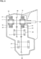
- ball bearings 1 as described above are usable as bearings of an electric vehicle transmission 32 that reduces rotation of electric motors 31 of an electric vehicle such as a battery electric vehicle (EV) or a hybrid electric vehicle (HEV).
- the bearings of the electric vehicle transmission 32 rotate at the number of rotations in a low-speed to high-speed wide rotation range while the vehicle is travelling, and are used under the conditions that, while the bearings are rotating at the highest speed, the dmn (ball pitch circle diameter (mm) X the number of rotations (min- 1 )) value exceeds 2 million.
- the transmission of Fig. 8 includes stators 33 and rotors 34 of the electric motors 31; a rotary shaft 35 coupled to the rotors 34, ball bearings 1 rotatably supporting the rotary shaft 35; a second rotary shaft 36 and a third rotary shaft 37 both arranged parallel to the rotary shaft 35; a first gear train 38 that transmits rotation of the rotary shaft 35 to the second rotary shaft 36; and a second gear train 39 that transmits rotation of the second rotary shaft 36 to the third rotary shaft 37.
- the stators 33 are annular stationary members, and the rotors 34 as the rotary members are disposed inside the respective stators 33. When the stators 33 are energized, the rotors 34 rotate due to the electromagnetic forces acting between the stators 33 and the rotors 34, and the rotation of the rotors 34 is inputted/transmitted to the rotary shaft 35.
- each cage claw portion 22 has an H-shaped cross section due to the outer-diameter-side axial groove 24 in the radially outer surface 23 of the cage claw portion 22 and the inner-diameter-side axial groove 26 in the radially inner surface 25 of the cage claw portion 22, it is possible to reduce the mass of the cage claw portions 22 while ensuring the moment of inertia of area of the cage claw portions 22 (while making the cage claw portions 22 less likely to deform against the bending moment).
- the deformation amount by which the cage claw portions 22 formed with the outer-diameter-side axial grooves 24 and the inner-diameter-side axial grooves 26 are deformed by a centrifugal force can be reduced to at least 77% or less compared to the cage claw portions 22 that are not formed with the outer-diameter-side axial grooves 24 and the inner-diameter-side axial grooves 26.
- the portions of the circumferentially opposed surfaces 27 of each cage claw portion 22 which circumferentially support the balls 5 are flat surfaces extending parallel to the imaginary straight line connecting the center of the cage circular annular portion 21 and the center of the cage claw portion 22 to each other when seen in the axial direction such that when the cage claw portion 22 is moved radially outwardly by a centrifugal force, the circumferentially opposed surfaces 27 do not interfere with the balls 5.
- boundary lubrication condition is the condition in which sliding contact surfaces are lubricated by an oil film comprising several molecular layers (about 10 -5 to 10 -6 mm) of lubricating oil adsorbed on the sliding contact surfaces, and minute protrusions and recesses of the sliding contact surfaces are in direct contact with each other.
- the fluid lubrication condition is the condition in which an oil film (e.g., about 10 -3 to 10 -1 mm) due to the wedge film effect is formed between sliding contact surfaces, and, due to the oil film, the sliding contact surfaces are not in direct contact with each other (i.e., they are in indirect contact with each other via the oil film). Since, when the fluid lubricating condition is generated due to the generation of the wedge film effect, the sliding resistance of the seal member becomes substantially zero, the bearing can be used at a high peripheral speed, which was impossible with conventional seals.
- an oil film e.g., about 10 -3 to 10 -1 mm
- a cage circular annular portion 21 which has a chamfer 47 obliquely extending, in a cross section perpendicular to the circumferential direction, to connect the cage-side sliding contact surface 40 and the cage guided surface 29 to each other, lubricating oil introduced into the space between the cage circular annular portion 21 and the seal member 6 through the inner-diameter-side axial grooves 26 from the radially inner areas of the cage claw portions 22 can be smoothly fed along the chamfer 47 and led onto the cage-side sliding contact surface 40, by a centrifugal force.
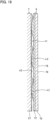
- a plurality of axial protrusions 42 are formed on the seal-side sliding contact surface 41 at constant pitches in the circumferential direction.
- the axial protrusions 42 are formed, with a mold, on the rubber part 17 of the seal member 6.
- the cross section of each axial protrusion 42 along the circumferential direction has an axially convex circular arc shape.
- the axial protrusion 42 has an axial height set to 5% or less of the circumferential width dimension of the axial protrusion 42. In Fig. 19 , the axial height of the axial protrusion 42 is exaggeratedly shown so that the axial protrusion 42 can be seen clearly.
- the cage-side sliding contact surface 40 is a circular annular flat surface extending in the direction perpendicular to the axial direction, and is formed with no axial protrusions 42.
- the axial protrusions 42 are disposed at positions where the axial protrusions 42 overlap with the pitch circle of the balls 5 (imaginary circle connecting the centers of the balls 5), or disposed radially outwardly of the pitch circle of the balls 5.
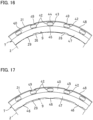
- the axial protrusions 42 each have a parallel apex portion 43, a first inclined apex portion 44 and a second inclined apex portion 45.
- the parallel apex portion 43 is a portion of the axial protrusion 42 having an axially circular arc convex shape in crosssections along the circumferential direction whose apex height is radially uniform.
- the first inclined apex portion 44 is a portion of the axial protrusion 42 having an axially convex circular arc shape in cross sections along the circumferential direction whose apex height gradually decreases radially outward from the radially outer end of the parallel apex portion 43.
- the second inclined apex portion 45 is a portion of the axial protrusion 42 having an axially convex circular arc shape in cross sections along the circumferential direction whose apex height gradually decreases radially inwardly from the radially inner end of the parallel apex portion 43.
- the cross sections of the first and second inclined apex portions 44 and 45 perpendicular to the circumferential direction have a rounded shape smoothly connected to the parallel apex portion 43.
- each first inclined apex portion 44 perpendicular to the circumferential direction has a rounded shape, and thus the first inclined apex portion 44 and the parallel apex portion 43 are smoothly connected to each other, when, with torsional deformation of the cage circular annular portion 21 relatively large, an oil film due to the wedge film effect is formed between the cage-side sliding contact surface 40, and the parallel apex portion 43 and the first inclined apex portion 44, the oil film can be formed stably.
- a seal member 6 is disposed at one of the end openings of the annular space 4 on both axial sides thereof, and a seal member 61 is disposed on the other end opening, too. Lubricant is sealed in the portion of the annular space 4 between the seal members 6 and 61.
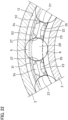
- each cage claw portion 22 has circumferentially opposed surfaces 27 circumferentially opposed to the corresponding balls 5, respectively.
- the portions of the circumferentially opposed surfaces 27 which circumferentially support the balls 5 are flat surfaces extending such that when the cage claw portion 22 is moved radially outwardly by a centrifugal force, the circumferentially opposed surfaces 27 do not interfere with the balls 5.
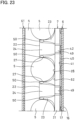
- Fig. 22 illustrates that when the cage claw portion 22 is moved radially outwardly by a centrifugal force, the circumferentially opposed surfaces 27 do not interfere with the balls 5.
- the circumferentially opposed surfaces 27 are flat surfaces inclined to gradually approach, in the radially inward direction, the imaginary straight line connecting the center of the cage circular annular portion 21 and the center of the cage claw portion 22 to each other (flat surfaces extending such that the circumferential width of the cage claw portion 22 gradually decreases in the radially inward direction), when seen in the axial direction.
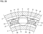
- the cage circular annular portion 21 includes a step 62 radially outwardly rising from the level of the radially outer surface portions of the cage claw portions 22 at their roots. Due to the formation of the step 62, when lubricant sealed in the annular space 4 is moved toward the cage circular annular portion 21 along the outer-diameter-side axial grooves 24, the lubricant can be partially stopped by the step 62, and returned to the balls 5.
- each circumferentially opposed surface 27 and the corresponding axially opposed surface 28 are connected together via a composite rounded curved surface.
- the curved surface connecting the circumferentially opposed surface 27 and the axially opposed surface 28 to each other is constituted by a distal-end-side rounded surface portion 63 connected to the circumferentially opposed surface 27, and having a part-cylindrical shape with a radius of curvature R2 smaller than the radius R1 of the ball 5; a root-side rounded surface portion 64 connected to the axially opposed surface 28, and having a part-cylindrical shape with a radius of curvature R3 larger than the radius R1 of the ball 5; and an intermediate rounded surface portion 65 smoothly connecting the distal-end-side rounded surface portion 63 and the root-side rounded surface portion 64 to each other.
- This ball bearing 1 is the same in operation and effects as the third embodiment.
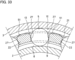
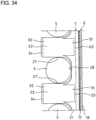
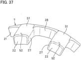
- Figs. 32 to 37 illustrate a ball bearing 1 according to the sixth embodiment which is not part of the claimed invention.
- the elements of the sixth embodiment corresponding to those of the above embodiments are denoted by the same reference numerals, and their description is omitted.
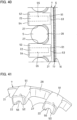
- a root-side guided surface 51 that comes into sliding contact with the one outer ring groove shoulder 13 is formed at the portion of the radially outer surface of the cage circular annular portion 21 corresponding to the root of each cage claw portion 22.
- a distal-end-side guided surface 52 that comes into sliding contact with the other outer ring groove shoulder 13 is formed on the radially outer surface of the axial end portion of the cage claw portion 22 on its distal end side.
- each cage claw portion 22 has, in its radially inner surface, an oil reservoir groove 55 axially extending from the distal end of the cage claw portion 22 toward the cage circular annular portion 21.
- the oil reservoir groove 55 rises to the radially inner surface of the cage 7 at the position radially opposed to the inner ring groove shoulder 9 closer to the cage circular annular portion 21.
- the oil reservoir groove 55 does not axially extend through the cage 7.
- the oil reservoir groove 55 may, however, axially extend through the radially inner surface of the cage 7.
- lubricating oil radially outwardly scattered by a centrifugal force can be stored in the oil reservoir grooves 55, and supplied to the inner ring 2.
- the relief recess 56 has an axial width wider than the axial width of the outer ring raceway groove 12, and extends in the circumferential direction. As illustrated in Fig. 42 , the relief recess 56 is arranged to cover the entire axial width of the outer ring raceway groove 12. That is, the end of the relief recess 56 closer to the root-side guided surface 51 is located at a position displaced toward the one outer ring groove shoulder 13 (outer ring groove shoulder 13 closer to the cage circular annular portion 21) from the boundary between the one outer ring groove shoulder 13 and the outer ring raceway groove 12.
- the end of the relief recess 56 closer to the distal-end-side guided surface 52 is located at a position displaced toward the other outer ring groove shoulder 13 (outer ring groove shoulder 13 remoter from the cage circular annular portion 21) from the boundary between the other outer ring groove shoulder 13 and the outer ring raceway groove 12. Both axial ends of the relief recess 56 rise while being inclined to the root-side guided surface 51 and the distal-end-side guided surface 52, respectively.
- the relief recess 56 is a portion recessed relative to the root-side guided surface 51 (or the distal-end-side guided surface 52) so as to have an inner surface at a position retracted radially inwardly relative to the root-side guided surface 51 (or the distal-end-side guided surface 52).
- the inner surface of the relief groove 56 is a flat surface extending in the direction perpendicular to the radial direction.
- the ball bearing 1 of this embodiment is the same in operation and effects as the sixth and seventh embodiments.
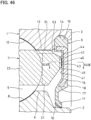
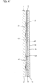
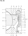
- Figs. 46 and 47 illustrate a ball bearing 1 according to the ninth embodiment of the present invention.
- the ninth embodiment corresponds to the combination of the sixth embodiment (of Figs. 32 to 37 ) and the sliding contact structure of the cage 7 and the seal member 6 in the second embodiment (sliding contact structure of the cage-side sliding contact surface 40 and the seal-side sliding contact surface 41 in Fig. 12 ). Therefore, the elements of the ninth embodiment corresponding to those of the above relevant embodiments are denoted by the same reference numerals, and their description is omitted.
- each of the above embodiments exemplifies an oil-lubricated ball bearing 1, in which lubricating oil is used as the lubricant for lubricating the interior of the bearing
- the present invention is also applicable to a ball bearing 1 lubricated by grease, i.e., a ball bearing 1 in which grease is used as the lubricant for lubricating the interior of the bearing.
- Grease is a semisolid lubricant containing lubricating oil and a thickener dispersed in the lubricating oil.
Landscapes
- Engineering & Computer Science (AREA)
- General Engineering & Computer Science (AREA)
- Mechanical Engineering (AREA)
- Rolling Contact Bearings (AREA)
Claims (12)
- Kugellager, umfassend:einen Innenring (2);einen Außenring (3), der radial außerhalb des Innenrings (2) und koaxial dazu angeordnet ist;eine Vielzahl Kugeln (5), die in einem ringförmigen Raum (4) zwischen dem Innenring (2) und dem Außenring (3) angeordnet sind;ein ringförmiges Dichtungselement (6), das eine axiale Endöffnung des ringförmigen Raums (4) schließt; undeinen Käfig (7), der aus Harz gemacht ist und die Kugeln (5) hält,wobei der Käfig (7) einen Käfigkreisringabschnitt (21) umfasst, der sich in Umfangsrichtung durch einen Raum erstreckt, der axial zwischen dem Dichtungselement (6) und dem Raum, durch den die Kugeln (5) laufen, eingezwängt ist; undKäfigklauenabschnitte (22), die eine Kragarmstruktur aufweisen, sich axial von dem Käfigkreisringabschnitt (21) erstrecken und jeweils zwischen einem zugeordneten Paar der Kugeln (5) in Umfangsrichtung benachbart zueinander angeordnet sind,dadurch gekennzeichnet, dass der Käfigkreisringabschnitt (21) eine käfigseitige Gleitkontaktfläche (40) aufweist, die dem Dichtungselement (6) axial gegenüberliegt und konfiguriert ist, in Gleitkontakt mit dem Dichtungselement (6) zu kommen,wobei das Dichtungselement (6) eine dichtungsseitige Gleitkontaktfläche (41) aufweist, die konfiguriert ist, in Gleitkontakt mit der käfigseitigen Gleitkontaktfläche (40) zu kommen,wobei eine Vielzahl axialer Vorsprünge (42), die jeweils eine axial konvexe Kreisbogenform im Querschnitt entlang einer Umfangsrichtung aufweisen, an einer von der käfigseitigen Gleitkontaktfläche (40) und der dichtungsseitigen Gleitkontaktfläche (41) in konstanten Abständen in der Umfangsrichtung ausgebildet sind, unddadurch gekennzeichnet, dass jeder der Käfigklauenabschnitte (22) in einer radial äußeren Fläche (23) des Käfigklauenabschnitts (22) eine außendurchmesserseitige Axialnut (24) aufweist, die sich axial von einem distalen Ende des Käfigklauenabschnitts (22) in Richtung des Käfigkreisringabschnitts (21) erstreckt und so geformt ist, dass sich eine Position eines Bodens der außendurchmesserseitigen Axialnut (24) schrittweise von dem distalen Ende des Käfigklauenabschnitts (22) in Richtung des Käfigkreisringabschnitts (21) radial nach außen ändert.
- Das Kugellager nach Anspruch 1, wobei jeder der Käfigklauenabschnitte (22) eine axiale Länge aufweist, die größer als ein Radius von jeder der Kugeln (5) ist, und wobei jeder der Käfigklauenabschnitte (22) in Umfangsrichtung gegenüberliegende Flächen (27) aufweist, die in Umfangsrichtung dem zugeordneten Paar der Kugeln (5) jeweils gegenüberliegenden und von denen Abschnitte, die konfiguriert sind, das zugeordnete Paar der Kugeln (5) in Umfangsrichtung zu stützen, gerade Abschnitte sind, die keine Neigung in Umfangsrichtung aufweisen und sich in einer axialen Richtung gerade erstrecken, damit keine Axialkomponentenkräfte beim Stützen des zugeordneten Paars der Kugeln (5) erzeugt werden.
- Das Kugellager nach Anspruch 2, wobei sich von den in Umfangsrichtung gegenüberliegenden Flächen (27) von jedem der Käfigklauenabschnitte (22) die Abschnitte, die konfiguriert sind, das zugeordnete Paar der Kugeln (5) in Umfangsrichtung zu stützen, parallel zu einer gedachten geraden Linie erstrecken, die eine Mitte des Käfigkreisringabschnitts (21) und eine Mitte des Käfigklauenabschnitts (22) miteinander verbindet, damit sich die in Umfangsrichtung gegenüberliegenden Flächen (27) mit dem zugeordneten Paar der Kugeln (5) nicht überlagern, wenn der Käfigklauenabschnitt (22) durch eine Zentrifugalkraft radial nach außen bewegt wird.
- Das Kugellager nach einem der Ansprüche 1 bis 3, wobei jeder der axialen Vorsprünge (42) umfasst:einen parallelen Scheitelabschnitt (43), der eine axial konvexe Kreisbogenkonvexform im Querschnitt entlang der Umfangsrichtung aufweist, dessen Scheitelhöhe radial einheitlich ist; undeinen geneigten Scheitelabschnitt (44), der eine axiale Kreisbogenkonvexform im Querschnitt entlang der Umfangsrichtung aufweist, dessen Scheitelhöhe schrittweise von einem radial äußeren Ende des parallelen Scheitelabschnitts (43) radial nach außen abnimmt.
- Das Kugellager nach Anspruch 4, wobei ein Querschnitt des geneigten Scheitelabschnitts (44) von jedem der axialen Vorsprünge (42) senkrecht zu der Umfangsrichtung eine abgerundete Form aufweist, die stetig mit dem parallelen Scheitelabschnitt (43) verbunden ist.
- Das Kugellager nach einem der Ansprüche 1 bis 5, wobei die axialen Vorsprünge (42) an Positionen angeordnet sind, wo die axialen Vorsprünge (42) mit einem Teilkreis der Kugeln (5) überlappen oder radial außerhalb des Teilkreises angeordnet sind.
- Das Kugellager nach einem der Ansprüche 1 bis 6, wobei die axialen Vorsprünge (42) an der dichtungsseitigen Gleitkontaktfläche (41) ausgebildet sind,wobei das Dichtungselement (6) einen ringförmigen Metallkern (16) und einen Kautschukteil (17) umfasst, der durch Vulkanisation an eine Fläche des Metallkerns (16) gebunden ist, undwobei die axialen Vorsprünge (42) aus demselben Material wie der Kautschukteil (17) gebildet sind.
- Das Kugellager nach einem der Ansprüche 1 bis 7, wobei der Käfigkreisringabschnitt (21) an einem Innenumfang des Käfigkreisringabschnitts (21) eine Käfigführungsfläche (29) aufweist, die konfiguriert ist, geführt zu werden, während sie in Gleitkontakt mit einem Außenumfang des Innenrings (2) kommt.
- Das Kugellager nach Anspruch 8, wobei der Käfig (7), der aus Harz hergestellt ist, in einem Innenumfang des Käfigs (7) innendurchmesserseitige Axialnuten (26) aufweist, die sich axial durch radial innere Flächen (25) der jeweiligen Käfigklauenabschnitte (22) und die Käfigführungsfläche (29) erstrecken.
- Das Kugellager nach Anspruch 8 oder 9, wobei der Käfigkreisringabschnitt (21) eine Abschrägung (47) aufweist, die sich in einem Querschnitt senkrecht zu der Umfangsrichtung geneigt erstreckt, um die käfigseitige Gleitkontaktfläche (40) und die Käfigführungsfläche (29) miteinander zu verbinden.
- Das Kugellager nach einem der Ansprüche 1 bis 10, wobei ein axiales Ende des ringförmigen Raums (4) entgegengesetzt zu einem axialen Ende des ringförmigen Raums (4), das von dem Dichtungselement (6) geschlossen wird, nicht mit einem zusätzlichen Dichtungselement (6) ausgestattet ist und offen ist, so dass von der Außenseite zugeführtes Schmieröl durch diese Öffnung in den ringförmigen Raum (4) eindringt.
- Das Kugellager nach einem der Ansprüche 1 bis 11, wobei das Kugellager als ein Lager eines Elektromotors (31) eines Elektrofahrzeugs eingesetzt wird oder ein Lager eines Elektrofahrzeuggetriebes (32) zur Umdrehungsreduzierung des Elektromotors (31).
Applications Claiming Priority (5)
| Application Number | Priority Date | Filing Date | Title |
|---|---|---|---|
| JP2020138674A JP7630245B2 (ja) | 2020-08-19 | 2020-08-19 | 玉軸受 |
| JP2020138678A JP7515342B2 (ja) | 2020-08-19 | 2020-08-19 | シール付玉軸受 |
| JP2020138672 | 2020-08-19 | ||
| JP2021119580A JP2022036002A (ja) | 2020-08-19 | 2021-07-20 | 玉軸受 |
| PCT/JP2021/029377 WO2022039057A1 (ja) | 2020-08-19 | 2021-08-06 | 玉軸受 |
Publications (3)
| Publication Number | Publication Date |
|---|---|
| EP4202242A1 EP4202242A1 (de) | 2023-06-28 |
| EP4202242A4 EP4202242A4 (de) | 2024-01-24 |
| EP4202242B1 true EP4202242B1 (de) | 2025-04-09 |
Family
ID=80322749
Family Applications (1)
| Application Number | Title | Priority Date | Filing Date |
|---|---|---|---|
| EP21858204.7A Active EP4202242B1 (de) | 2020-08-19 | 2021-08-06 | Kugellager |
Country Status (4)
| Country | Link |
|---|---|
| US (2) | US12146524B2 (de) |
| EP (1) | EP4202242B1 (de) |
| CN (1) | CN115943262B (de) |
| WO (1) | WO2022039057A1 (de) |
Families Citing this family (1)
| Publication number | Priority date | Publication date | Assignee | Title |
|---|---|---|---|---|
| US12404898B2 (en) * | 2021-11-25 | 2025-09-02 | Ntn Corporation | Sealed bearing |
Family Cites Families (20)
| Publication number | Priority date | Publication date | Assignee | Title |
|---|---|---|---|---|
| US2038010A (en) * | 1934-11-20 | 1936-04-21 | Fed Bearings Co Inc | Ball bearing |
| IT8454107U1 (it) * | 1984-12-04 | 1986-06-04 | Riv Skf Officine Di Villar Perosa S P A | Gabbia distanziatrice per le sfere di un cuscinetto a sfere |
| JP3035766B2 (ja) | 1994-02-18 | 2000-04-24 | 光洋精工株式会社 | 玉軸受用保持器および玉軸受 |
| JP3035766U (ja) | 1995-12-28 | 1997-04-04 | 多喜蔵 大内 | 磁石を利用した、しゃもじケース蓋の自動開閉 |
| JPH11210757A (ja) * | 1998-01-23 | 1999-08-03 | Koyo Seiko Co Ltd | 合成樹脂製冠形保持器 |
| JP2002130292A (ja) | 2000-10-17 | 2002-05-09 | Nsk Ltd | 玉軸受 |
| JP2004092682A (ja) | 2002-08-29 | 2004-03-25 | Nsk Ltd | 転がり軸受用保持器 |
| JP2004346973A (ja) * | 2003-05-20 | 2004-12-09 | Ntn Corp | 玉軸受用の合成樹脂製保持器 |
| JP2005133818A (ja) * | 2003-10-30 | 2005-05-26 | Koyo Seiko Co Ltd | 転がり軸受 |
| JP2005214259A (ja) * | 2004-01-28 | 2005-08-11 | Nsk Ltd | 玉軸受及びオルタネータ用玉軸受 |
| JP2007303600A (ja) | 2006-05-12 | 2007-11-22 | Nsk Ltd | 転がり軸受 |
| JP2008175257A (ja) * | 2007-01-17 | 2008-07-31 | Nsk Ltd | 深溝玉軸受 |
| JP2008249108A (ja) | 2007-03-30 | 2008-10-16 | Nsk Ltd | 転がり軸受 |
| JP2009008170A (ja) * | 2007-06-28 | 2009-01-15 | Nsk Ltd | 樹脂製保持器及び該保持器を使用した玉軸受 |
| FR2994721B1 (fr) * | 2012-08-22 | 2015-07-03 | Skf Ab | Cage pour palier a roulement, palier a roulement et direction electrique de vehicule automobile |
| WO2016143786A1 (ja) | 2015-03-09 | 2016-09-15 | Ntn株式会社 | シール付軸受 |
| JP6523994B2 (ja) | 2015-03-09 | 2019-06-05 | Ntn株式会社 | シール付軸受 |
| JP6841067B2 (ja) * | 2017-02-06 | 2021-03-10 | 株式会社ジェイテクト | 玉軸受 |
| JP6874455B2 (ja) | 2017-03-22 | 2021-05-19 | 株式会社ジェイテクト | 転がり軸受 |
| EP3919766B1 (de) * | 2019-01-29 | 2024-06-05 | NTN Corporation | Kugellager |
-
2021
- 2021-08-06 EP EP21858204.7A patent/EP4202242B1/de active Active
- 2021-08-06 US US18/021,098 patent/US12146524B2/en active Active
- 2021-08-06 CN CN202180050626.1A patent/CN115943262B/zh active Active
- 2021-08-06 WO PCT/JP2021/029377 patent/WO2022039057A1/ja not_active Ceased
-
2024
- 2024-10-11 US US18/913,415 patent/US20250035153A1/en active Pending
Also Published As
| Publication number | Publication date |
|---|---|
| CN115943262B (zh) | 2026-02-10 |
| US20230296132A1 (en) | 2023-09-21 |
| WO2022039057A1 (ja) | 2022-02-24 |
| CN115943262A (zh) | 2023-04-07 |
| EP4202242A4 (de) | 2024-01-24 |
| EP4202242A1 (de) | 2023-06-28 |
| US20250035153A1 (en) | 2025-01-30 |
| US12146524B2 (en) | 2024-11-19 |
Similar Documents
| Publication | Publication Date | Title |
|---|---|---|
| US8292512B2 (en) | Ball bearing and supporting construction | |
| CN102119281B (zh) | 滚珠轴承以及混合动力车用变速器 | |
| US11828328B2 (en) | Ball bearing | |
| JP2022036002A (ja) | 玉軸受 | |
| JP7270409B2 (ja) | 玉軸受 | |
| US20250035153A1 (en) | Ball bearing | |
| JP7515342B2 (ja) | シール付玉軸受 | |
| JP2015124796A (ja) | 円錐ころ軸受 | |
| JP7630245B2 (ja) | 玉軸受 | |
| JP7699528B2 (ja) | シール付玉軸受 | |
| JP7758515B2 (ja) | 転がり軸受 | |
| US20250027539A1 (en) | Sealed bearing | |
| JP7814183B2 (ja) | グリース封入玉軸受 | |
| JP2022146663A (ja) | 軸受 | |
| JP7724145B2 (ja) | シール付玉軸受 | |
| JP2026045801A (ja) | 玉軸受 | |
| WO2024018952A1 (ja) | 玉軸受 | |
| KR20260022329A (ko) | 시일을 갖는 볼 베어링 및 베어링 장치 | |
| WO2024241906A1 (ja) | 玉軸受 | |
| JP2025151834A (ja) | 玉軸受 | |
| WO2024019012A1 (ja) | 外輪案内保持器付き玉軸受および偏心回転装置 |
Legal Events
| Date | Code | Title | Description |
|---|---|---|---|
| STAA | Information on the status of an ep patent application or granted ep patent |
Free format text: STATUS: THE INTERNATIONAL PUBLICATION HAS BEEN MADE |
|
| PUAI | Public reference made under article 153(3) epc to a published international application that has entered the european phase |
Free format text: ORIGINAL CODE: 0009012 |
|
| STAA | Information on the status of an ep patent application or granted ep patent |
Free format text: STATUS: REQUEST FOR EXAMINATION WAS MADE |
|
| 17P | Request for examination filed |
Effective date: 20230303 |
|
| AK | Designated contracting states |
Kind code of ref document: A1 Designated state(s): AL AT BE BG CH CY CZ DE DK EE ES FI FR GB GR HR HU IE IS IT LI LT LU LV MC MK MT NL NO PL PT RO RS SE SI SK SM TR |
|
| DAV | Request for validation of the european patent (deleted) | ||
| DAX | Request for extension of the european patent (deleted) | ||
| A4 | Supplementary search report drawn up and despatched |
Effective date: 20231221 |
|
| RIC1 | Information provided on ipc code assigned before grant |
Ipc: F16C 33/44 20060101ALI20231218BHEP Ipc: F16C 33/78 20060101ALI20231218BHEP Ipc: F16J 15/3216 20160101ALI20231218BHEP Ipc: F16C 33/38 20060101ALI20231218BHEP Ipc: F16J 15/324 20160101ALI20231218BHEP Ipc: F16C 33/76 20060101ALI20231218BHEP Ipc: F16C 33/66 20060101ALI20231218BHEP Ipc: F16C 33/41 20060101ALI20231218BHEP Ipc: F16C 19/06 20060101AFI20231218BHEP |
|
| GRAP | Despatch of communication of intention to grant a patent |
Free format text: ORIGINAL CODE: EPIDOSNIGR1 |
|
| STAA | Information on the status of an ep patent application or granted ep patent |
Free format text: STATUS: GRANT OF PATENT IS INTENDED |
|
| INTG | Intention to grant announced |
Effective date: 20241125 |
|
| GRAS | Grant fee paid |
Free format text: ORIGINAL CODE: EPIDOSNIGR3 |
|
| GRAA | (expected) grant |
Free format text: ORIGINAL CODE: 0009210 |
|
| STAA | Information on the status of an ep patent application or granted ep patent |
Free format text: STATUS: THE PATENT HAS BEEN GRANTED |
|
| AK | Designated contracting states |
Kind code of ref document: B1 Designated state(s): AL AT BE BG CH CY CZ DE DK EE ES FI FR GB GR HR HU IE IS IT LI LT LU LV MC MK MT NL NO PL PT RO RS SE SI SK SM TR |
|
| REG | Reference to a national code |
Ref country code: GB Ref legal event code: FG4D |
|
| REG | Reference to a national code |
Ref country code: CH Ref legal event code: EP |
|
| REG | Reference to a national code |
Ref country code: DE Ref legal event code: R096 Ref document number: 602021029049 Country of ref document: DE |
|
| REG | Reference to a national code |
Ref country code: IE Ref legal event code: FG4D |
|
| REG | Reference to a national code |
Ref country code: NL Ref legal event code: MP Effective date: 20250409 |
|
| PG25 | Lapsed in a contracting state [announced via postgrant information from national office to epo] |
Ref country code: NL Free format text: LAPSE BECAUSE OF FAILURE TO SUBMIT A TRANSLATION OF THE DESCRIPTION OR TO PAY THE FEE WITHIN THE PRESCRIBED TIME-LIMIT Effective date: 20250409 |
|
| REG | Reference to a national code |
Ref country code: AT Ref legal event code: MK05 Ref document number: 1783741 Country of ref document: AT Kind code of ref document: T Effective date: 20250409 |
|
| PG25 | Lapsed in a contracting state [announced via postgrant information from national office to epo] |
Ref country code: FI Free format text: LAPSE BECAUSE OF FAILURE TO SUBMIT A TRANSLATION OF THE DESCRIPTION OR TO PAY THE FEE WITHIN THE PRESCRIBED TIME-LIMIT Effective date: 20250409 Ref country code: PT Free format text: LAPSE BECAUSE OF FAILURE TO SUBMIT A TRANSLATION OF THE DESCRIPTION OR TO PAY THE FEE WITHIN THE PRESCRIBED TIME-LIMIT Effective date: 20250811 Ref country code: ES Free format text: LAPSE BECAUSE OF FAILURE TO SUBMIT A TRANSLATION OF THE DESCRIPTION OR TO PAY THE FEE WITHIN THE PRESCRIBED TIME-LIMIT Effective date: 20250409 |
|
| PGFP | Annual fee paid to national office [announced via postgrant information from national office to epo] |
Ref country code: DE Payment date: 20250828 Year of fee payment: 5 |
|
| REG | Reference to a national code |
Ref country code: LT Ref legal event code: MG9D |
|
| PG25 | Lapsed in a contracting state [announced via postgrant information from national office to epo] |
Ref country code: NO Free format text: LAPSE BECAUSE OF FAILURE TO SUBMIT A TRANSLATION OF THE DESCRIPTION OR TO PAY THE FEE WITHIN THE PRESCRIBED TIME-LIMIT Effective date: 20250709 Ref country code: GR Free format text: LAPSE BECAUSE OF FAILURE TO SUBMIT A TRANSLATION OF THE DESCRIPTION OR TO PAY THE FEE WITHIN THE PRESCRIBED TIME-LIMIT Effective date: 20250710 |
|
| PG25 | Lapsed in a contracting state [announced via postgrant information from national office to epo] |
Ref country code: PL Free format text: LAPSE BECAUSE OF FAILURE TO SUBMIT A TRANSLATION OF THE DESCRIPTION OR TO PAY THE FEE WITHIN THE PRESCRIBED TIME-LIMIT Effective date: 20250409 |
|
| PG25 | Lapsed in a contracting state [announced via postgrant information from national office to epo] |
Ref country code: BG Free format text: LAPSE BECAUSE OF FAILURE TO SUBMIT A TRANSLATION OF THE DESCRIPTION OR TO PAY THE FEE WITHIN THE PRESCRIBED TIME-LIMIT Effective date: 20250409 |
|
| PG25 | Lapsed in a contracting state [announced via postgrant information from national office to epo] |
Ref country code: HR Free format text: LAPSE BECAUSE OF FAILURE TO SUBMIT A TRANSLATION OF THE DESCRIPTION OR TO PAY THE FEE WITHIN THE PRESCRIBED TIME-LIMIT Effective date: 20250409 |
|
| PG25 | Lapsed in a contracting state [announced via postgrant information from national office to epo] |
Ref country code: AT Free format text: LAPSE BECAUSE OF FAILURE TO SUBMIT A TRANSLATION OF THE DESCRIPTION OR TO PAY THE FEE WITHIN THE PRESCRIBED TIME-LIMIT Effective date: 20250409 |
|
| PGFP | Annual fee paid to national office [announced via postgrant information from national office to epo] |
Ref country code: FR Payment date: 20250826 Year of fee payment: 5 |
|
| PG25 | Lapsed in a contracting state [announced via postgrant information from national office to epo] |
Ref country code: RS Free format text: LAPSE BECAUSE OF FAILURE TO SUBMIT A TRANSLATION OF THE DESCRIPTION OR TO PAY THE FEE WITHIN THE PRESCRIBED TIME-LIMIT Effective date: 20250709 |
|
| PG25 | Lapsed in a contracting state [announced via postgrant information from national office to epo] |
Ref country code: IS Free format text: LAPSE BECAUSE OF FAILURE TO SUBMIT A TRANSLATION OF THE DESCRIPTION OR TO PAY THE FEE WITHIN THE PRESCRIBED TIME-LIMIT Effective date: 20250809 |
|
| PG25 | Lapsed in a contracting state [announced via postgrant information from national office to epo] |
Ref country code: LV Free format text: LAPSE BECAUSE OF FAILURE TO SUBMIT A TRANSLATION OF THE DESCRIPTION OR TO PAY THE FEE WITHIN THE PRESCRIBED TIME-LIMIT Effective date: 20250409 |
|
| REG | Reference to a national code |
Ref country code: DE Ref legal event code: R097 Ref document number: 602021029049 Country of ref document: DE |
|
| PG25 | Lapsed in a contracting state [announced via postgrant information from national office to epo] |
Ref country code: SM Free format text: LAPSE BECAUSE OF FAILURE TO SUBMIT A TRANSLATION OF THE DESCRIPTION OR TO PAY THE FEE WITHIN THE PRESCRIBED TIME-LIMIT Effective date: 20250409 Ref country code: DK Free format text: LAPSE BECAUSE OF FAILURE TO SUBMIT A TRANSLATION OF THE DESCRIPTION OR TO PAY THE FEE WITHIN THE PRESCRIBED TIME-LIMIT Effective date: 20250409 |
|
| PG25 | Lapsed in a contracting state [announced via postgrant information from national office to epo] |
Ref country code: CZ Free format text: LAPSE BECAUSE OF FAILURE TO SUBMIT A TRANSLATION OF THE DESCRIPTION OR TO PAY THE FEE WITHIN THE PRESCRIBED TIME-LIMIT Effective date: 20250409 |
|
| PG25 | Lapsed in a contracting state [announced via postgrant information from national office to epo] |
Ref country code: EE Free format text: LAPSE BECAUSE OF FAILURE TO SUBMIT A TRANSLATION OF THE DESCRIPTION OR TO PAY THE FEE WITHIN THE PRESCRIBED TIME-LIMIT Effective date: 20250409 |
|
| PG25 | Lapsed in a contracting state [announced via postgrant information from national office to epo] |
Ref country code: SK Free format text: LAPSE BECAUSE OF FAILURE TO SUBMIT A TRANSLATION OF THE DESCRIPTION OR TO PAY THE FEE WITHIN THE PRESCRIBED TIME-LIMIT Effective date: 20250409 |
|
| PG25 | Lapsed in a contracting state [announced via postgrant information from national office to epo] |
Ref country code: IT Free format text: LAPSE BECAUSE OF FAILURE TO SUBMIT A TRANSLATION OF THE DESCRIPTION OR TO PAY THE FEE WITHIN THE PRESCRIBED TIME-LIMIT Effective date: 20250409 |
|
| PLBE | No opposition filed within time limit |
Free format text: ORIGINAL CODE: 0009261 |
|
| STAA | Information on the status of an ep patent application or granted ep patent |
Free format text: STATUS: NO OPPOSITION FILED WITHIN TIME LIMIT |
|
| REG | Reference to a national code |
Ref country code: CH Ref legal event code: L10 Free format text: ST27 STATUS EVENT CODE: U-0-0-L10-L00 (AS PROVIDED BY THE NATIONAL OFFICE) Effective date: 20260218 |
|
| PG25 | Lapsed in a contracting state [announced via postgrant information from national office to epo] |
Ref country code: RO Free format text: LAPSE BECAUSE OF FAILURE TO SUBMIT A TRANSLATION OF THE DESCRIPTION OR TO PAY THE FEE WITHIN THE PRESCRIBED TIME-LIMIT Effective date: 20250409 |
|
| 26N | No opposition filed |
Effective date: 20260112 |
|
| REG | Reference to a national code |
Ref country code: CH Ref legal event code: H13 Free format text: ST27 STATUS EVENT CODE: U-0-0-H10-H13 (AS PROVIDED BY THE NATIONAL OFFICE) Effective date: 20260324 |
|
| PG25 | Lapsed in a contracting state [announced via postgrant information from national office to epo] |
Ref country code: MC Free format text: LAPSE BECAUSE OF FAILURE TO SUBMIT A TRANSLATION OF THE DESCRIPTION OR TO PAY THE FEE WITHIN THE PRESCRIBED TIME-LIMIT Effective date: 20250409 |
|
| PG25 | Lapsed in a contracting state [announced via postgrant information from national office to epo] |
Ref country code: LU Free format text: LAPSE BECAUSE OF NON-PAYMENT OF DUE FEES Effective date: 20250806 |