EP4202247A1 - Dispositif pour mouvement linéaire - Google Patents
Dispositif pour mouvement linéaire Download PDFInfo
- Publication number
- EP4202247A1 EP4202247A1 EP21858263.3A EP21858263A EP4202247A1 EP 4202247 A1 EP4202247 A1 EP 4202247A1 EP 21858263 A EP21858263 A EP 21858263A EP 4202247 A1 EP4202247 A1 EP 4202247A1
- Authority
- EP
- European Patent Office
- Prior art keywords
- ball screw
- bearing
- linear motion
- motion device
- nut
- Prior art date
- Legal status (The legal status is an assumption and is not a legal conclusion. Google has not performed a legal analysis and makes no representation as to the accuracy of the status listed.)
- Granted
Links
Images


Classifications
-
- F—MECHANICAL ENGINEERING; LIGHTING; HEATING; WEAPONS; BLASTING
- F16—ENGINEERING ELEMENTS AND UNITS; GENERAL MEASURES FOR PRODUCING AND MAINTAINING EFFECTIVE FUNCTIONING OF MACHINES OR INSTALLATIONS; THERMAL INSULATION IN GENERAL
- F16C—SHAFTS; FLEXIBLE SHAFTS; ELEMENTS OR CRANKSHAFT MECHANISMS; ROTARY BODIES OTHER THAN GEARING ELEMENTS; BEARINGS
- F16C29/00—Bearings for parts moving only linearly
- F16C29/04—Ball or roller bearings
- F16C29/06—Ball or roller bearings in which the rolling bodies circulate partly without carrying load
- F16C29/068—Ball or roller bearings in which the rolling bodies circulate partly without carrying load with the bearing body fully encircling the guide rail or track
- F16C29/0683—Ball or roller bearings in which the rolling bodies circulate partly without carrying load with the bearing body fully encircling the guide rail or track the bearing body encircles a rail or rod of circular cross-section, i.e. the linear bearing is not suited to transmit torque
- F16C29/0685—Ball or roller bearings in which the rolling bodies circulate partly without carrying load with the bearing body fully encircling the guide rail or track the bearing body encircles a rail or rod of circular cross-section, i.e. the linear bearing is not suited to transmit torque with balls
- F16C29/0688—Ball or roller bearings in which the rolling bodies circulate partly without carrying load with the bearing body fully encircling the guide rail or track the bearing body encircles a rail or rod of circular cross-section, i.e. the linear bearing is not suited to transmit torque with balls whereby a sleeve surrounds the circulating balls and thicker part of the sleeve form the load bearing tracks
-
- F—MECHANICAL ENGINEERING; LIGHTING; HEATING; WEAPONS; BLASTING
- F16—ENGINEERING ELEMENTS AND UNITS; GENERAL MEASURES FOR PRODUCING AND MAINTAINING EFFECTIVE FUNCTIONING OF MACHINES OR INSTALLATIONS; THERMAL INSULATION IN GENERAL
- F16H—GEARING
- F16H25/00—Gearings comprising primarily only cams, cam-followers and screw-and-nut mechanisms
- F16H25/18—Gearings comprising primarily only cams, cam-followers and screw-and-nut mechanisms for conveying or interconverting oscillating or reciprocating motions
- F16H25/20—Screw mechanisms
- F16H25/22—Screw mechanisms with balls, rollers, or similar members between the co-operating parts; Elements essential to the use of such members
- F16H25/2204—Screw mechanisms with balls, rollers, or similar members between the co-operating parts; Elements essential to the use of such members with balls
-
- F—MECHANICAL ENGINEERING; LIGHTING; HEATING; WEAPONS; BLASTING
- F16—ENGINEERING ELEMENTS AND UNITS; GENERAL MEASURES FOR PRODUCING AND MAINTAINING EFFECTIVE FUNCTIONING OF MACHINES OR INSTALLATIONS; THERMAL INSULATION IN GENERAL
- F16C—SHAFTS; FLEXIBLE SHAFTS; ELEMENTS OR CRANKSHAFT MECHANISMS; ROTARY BODIES OTHER THAN GEARING ELEMENTS; BEARINGS
- F16C35/00—Rigid support of bearing units; Housings, e.g. caps, covers
- F16C35/04—Rigid support of bearing units; Housings, e.g. caps, covers in the case of ball or roller bearings
- F16C35/06—Mounting or dismounting of ball or roller bearings; Fixing them onto shaft or in housing
- F16C35/067—Fixing them in a housing
-
- F—MECHANICAL ENGINEERING; LIGHTING; HEATING; WEAPONS; BLASTING
- F16—ENGINEERING ELEMENTS AND UNITS; GENERAL MEASURES FOR PRODUCING AND MAINTAINING EFFECTIVE FUNCTIONING OF MACHINES OR INSTALLATIONS; THERMAL INSULATION IN GENERAL
- F16H—GEARING
- F16H25/00—Gearings comprising primarily only cams, cam-followers and screw-and-nut mechanisms
- F16H25/18—Gearings comprising primarily only cams, cam-followers and screw-and-nut mechanisms for conveying or interconverting oscillating or reciprocating motions
- F16H25/20—Screw mechanisms
- F16H25/22—Screw mechanisms with balls, rollers, or similar members between the co-operating parts; Elements essential to the use of such members
-
- F—MECHANICAL ENGINEERING; LIGHTING; HEATING; WEAPONS; BLASTING
- F16—ENGINEERING ELEMENTS AND UNITS; GENERAL MEASURES FOR PRODUCING AND MAINTAINING EFFECTIVE FUNCTIONING OF MACHINES OR INSTALLATIONS; THERMAL INSULATION IN GENERAL
- F16H—GEARING
- F16H25/00—Gearings comprising primarily only cams, cam-followers and screw-and-nut mechanisms
- F16H25/18—Gearings comprising primarily only cams, cam-followers and screw-and-nut mechanisms for conveying or interconverting oscillating or reciprocating motions
- F16H25/20—Screw mechanisms
- F16H2025/2031—Actuator casings
-
- F—MECHANICAL ENGINEERING; LIGHTING; HEATING; WEAPONS; BLASTING
- F16—ENGINEERING ELEMENTS AND UNITS; GENERAL MEASURES FOR PRODUCING AND MAINTAINING EFFECTIVE FUNCTIONING OF MACHINES OR INSTALLATIONS; THERMAL INSULATION IN GENERAL
- F16H—GEARING
- F16H25/00—Gearings comprising primarily only cams, cam-followers and screw-and-nut mechanisms
- F16H25/18—Gearings comprising primarily only cams, cam-followers and screw-and-nut mechanisms for conveying or interconverting oscillating or reciprocating motions
- F16H25/20—Screw mechanisms
- F16H2025/2062—Arrangements for driving the actuator
- F16H2025/2075—Coaxial drive motors
Definitions
- the present invention relates to a linear motion device including a nut that moves in an axial direction with respect to a ball screw in accordance with rotation of the ball screw.
- a bearing for supporting the ball screw and a restricting member for restricting movement of the bearing are attached to the ball screw.
- an operator may remove the restricting member from the ball screw.
- the operator In order to remove the restricting member from the ball screw, the operator also needs to remove the bearing from the ball screw. Therefore, maintenance of the linear motion device requires considerable processing steps. Therefore, improvement in work efficiency of maintenance of the linear motion device is required.
- the present invention has been devised in order to solve the above problem, and it is therefore an object of the present invention to provide a linear motion device that can improve maintenance work efficiency.
- a linear motion device including a ball screw, a nut configured to move with respect to the ball screw in an axial direction thereof in accordance with rotation of the ball screw, a bearing mounted on an outer periphery of the ball screw, a housing configured to support the ball screw through the bearing, a nut holder configured to hold the nut therein and through which the ball screw passes, and a restricting member that has a through hole in a center portion thereof, is disposed between the bearing and the nut holder, is fixed to the housing in a state where the ball screw is inserted into the through hole, and restricts movement of the bearing in the axial direction in the housing, wherein the restricting member includes a cutout portion extending in a radial direction from an inner peripheral surface of the through hole to an outer peripheral surface of the restricting member.
- the work efficiency of maintenance of the linear motion device can be improved.
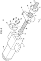
- FIG. 1 is an exploded view of a linear motion device 10 according to the present embodiment.
- the linear motion device 10 is, for example, a device for linearly moving a work table of a machine tool.
- the linear motion device 10 includes a ball screw 12, a bearing 14, a motor housing 16, a bearing limiting member 22, a motor 24, a nut 26, and a nut holder 30.
- each member constituting the linear motion device 10 will be described using an X-axis shown in FIG. 1 .
- the X-axis direction is parallel to an axial direction of the ball screw 12.
- An end portion of the ball screw 12 to which the bearing 14 is attached is referred to as a positive side, and an opposite end portion is referred to as a negative side.
- the motor housing 16 has a support portion (support hole) 18 bored so as to open in a side surface 16-1 on the negative side in the X-axis direction.
- the bearing 14 is attached to the end portion of the ball screw 12 on the positive side in the X-axis direction.
- a lock nut 20 is attached to an end portion of the ball screw 12 on the positive side in the X-axis direction.
- the lock nut 20 is disposed at a position closer to the end surface of the ball screw 12 on the positive side in the X-axis direction than the bearing 14 is.
- the bearing 14 is prevented from coming off the ball screw 12 by the lock nut 20.
- the end portion of the ball screw 12 on the positive side in the X-axis direction is inserted into the support portion 18 together with the bearing 14.
- the ball screw 12 is supported by the motor housing 16 via the bearing 14.
- the bearing limiting member 22 is mounted on the ball screw 12.
- the bearing limiting member 22 is disposed at a position farther from an end surface of the ball screw 12 on the positive side in the X-axis direction than the bearing 14 is.
- the opening of the support portion 18 is closed by the bearing limiting member 22.
- the bearing limiting member 22 is fixed to the side surface 16-1 of the motor housing 16 by bolts 38.
- the bearing limiting member 22 limits movement of the bearing 14 and the ball screw 12 in a direction in which the bearing 14 and the ball screw 12 come out of the support portion 18.
- the motor housing 16 is fixed to, for example, a bed of a machine tool.
- the motor housing 16 corresponds to a housing of the present invention.
- the end portion of the ball screw 12 on the positive side in the X-axis direction is connected to a drive shaft of the motor 24 inside the motor housing 16.
- the ball screw 12 is rotated about its axis by the motor 24.
- the nut 26 is screwed to the ball screw 12 via balls (not shown). As the ball screw 12 rotates, the nut 26 moves in the X-axis direction with respect to the ball screw 12.
- the nut 26 is held by the nut holder 30.
- the nut holder 30 is provided with a through hole 32 penetrating in the X-axis direction, and the nut 26 is accommodated in the through hole 32.
- a diameter of the through hole 32 is larger than an outer diameter of the bearing 14.
- the nut 26 has a flange 28.
- the flange 28 is formed at an end portion of the nut 26 on the negative side in the X-axis direction. In a state where the nut 26 is accommodated in the through hole 32 of the nut holder 30, the flange 28 is fixed to a side surface of the nut holder 30 on the negative side in the X-axis direction by bolts 34.
- the nut holder 30 moves together with the nut 26 in the X-axis direction with respect to the ball screw 12.
- a work table of a machine tool is fixed.
- the work table is linearly moved together with the nut holder 30.
- the bearing limiting member 22 is formed in a disk shape having a through hole 36 at a central portion thereof.
- a diameter of the through hole 36 of the bearing limiting member 22 is formed to be smaller than the outer diameter of the an outer race of the bearing 14 and larger than the outer diameter of an inner race.
- An outer diameter of the bearing limiting member 22 is formed to be larger than a diameter of the through hole 32 of the nut holder 30.
- a cutout portion 40 extending in the radial direction from an inner circumferential surface of the through hole 36 to an outer peripheral surface of the bearing limiting member 22 is formed.
- a width of the cutout portion 40 is smaller than the outer diameter of the ball screw 12.
- the bearing limiting member 22 corresponds to a restricting member of the present invention.
- FIG. 2 is a view showing a state in which the bearing limiting member 22 is removed from the ball screw 12.
- the ball screw 12 has two planar portions 42-1 and 42-2 that are formed by partially cutting out the outer peripheral surface thereof to be parallel to each other.
- the thickness of a portion of the ball screw 12 sandwiched between the two planar portions 42-1 and 42-2 is formed to be thinner than the width of the cutout portion 40 of the bearing limiting member 22.
- the bearing limiting member 22 can be removed from the ball screw 12.
- the bearing limiting member 22 can be attached to the ball screw 12.
- FIG. 3 is an exploded view of a linear motion device 44 according to a comparative example.
- the shape of a bearing limiting member 22 of the linear motion device 44 of the comparative example is partially different from the shape of the bearing limiting member 22 of the linear motion device 10 of the present embodiment.
- the bearing limiting member 22 of the linear motion device 44 of the comparative example does not have a configuration corresponding to the cutout portion 40 of the linear motion device 10 of the present embodiment.
- the other members of the linear motion device 44 of the comparative example are the same as those of the linear motion device 10 of the present embodiment.
- the outer diameter of the bearing limiting member 22 is larger than the diameter of the through hole 32 of the nut holder 30, and the bearing limiting member 22 cannot pass through an inner circumference of the nut holder 30.
- the outer diameter of the bearing 14 is smaller than the diameter of the through hole 32 of the nut holder 30, so that the bearing 14 can pass through the inner circumference of the nut holder 30.
- the linear motion device 44 when the linear motion device 44 is disassembled, if the bearing limiting member 22 is removed from the ball screw 12, the operator can pull out the ball screw 12 from the nut holder 30 even if the bearing 14 is attached to the ball screw 12. Similarly, when the linear motion device 44 is assembled, if the bearing limiting member 22 is removed from the ball screw 12, the operator can insert the ball screw 12 into the nut holder 30 even if the bearing 14 is attached to the ball screw 12.
- the linear motion device 44 of the comparative example when removing the bearing limiting member 22 from the ball screw 12, the operator also needs to remove the bearing 14 from the ball screw 12. Similarly, when attaching the bearing limiting member 22 to the ball screw 12, the operator needs to remove the bearing 14 from the ball screw 12. Since the linear motion device 44 of the comparative example requires considerable processing steps for maintenance, a linear motion device capable of improving work efficiency of maintenance is demanded.
- the bearing limiting member 22 has the cutout portion 40. Therefore, in a state where the bearing 14 is attached to the ball screw 12, an operator can remove the bearing limiting member 22 from the ball screw 12. Thus, the operator can pull out the ball screw 12 from the nut holder 30 without removing the bearing 14 from the ball screw 12. Further, the operator can attach the bearing limiting member 22 to the ball screw 12 in a state where the bearing 14 is attached to the ball screw 12. Thus, the operator can insert the ball screw 12 into the nut holder 30 in a state where the bearing 14 is attached to the ball screw 12. Thereafter, the operator can attach the bearing limiting member 22 to the ball screw 12 without removing the bearing 14 from the ball screw 12. Therefore, the maintenance work efficiency of the linear motion device 10 can be improved.
- the ball screw 12 has two planar portions 42-1 and 42-2 that are formed by cutting out the outer peripheral surface to be parallel to each other.
- the width of the cutout portion 40 of the bearing limiting member 22 is formed to be smaller than the outer diameter of the ball screw 12.
- FIG. 4 is a view illustrating a state in which the bearing limiting member 22 is removed from the ball screw 12.
- the ball screw 12 has one planar portion 46 formed by cutting out a part of the outer peripheral surface thereof.
- the thickness of the planar portion 46 and the outer peripheral surface of the ball screw 12 is formed to be thinner than the width of the cutout portion 40 of the bearing limiting member 22.
- the cutout portion 40 shown in FIG. 4 is formed so as to be shifted from the center of the through hole 36. Therefore, the extension line of the center line in the width direction of the cutout portion 40 does not pass through the center of the through hole 36.
- the cutout portion 40 shown in FIG. 2 is formed so as to extend toward the center of the through hole 36.
- the extension line of the center line in the width direction of the cutout portion 40 passes through the center of the through hole 36. It is adequate that the entire cutout portion 40 communicates with the through hole 36 in the width direction of the cutout portion 40.
- the cutout portion 40 may be formed to be deviated from the center of the through hole 36 or may be formed to extend toward the center of the through hole 36. The other configurations are the same as those of the linear motion device 10 of the first embodiment.
- the ball screw 12 has the planar portion 46 formed by cutting out a part of the outer peripheral surface of the ball screw 12.
- the width of the cutout portion 40 of the bearing limiting member 22 is formed to be smaller than the outer diameter of the ball screw 12.
- one planar portion 46 is formed in the ball screw 12, it is possible to ensure the strength of the bearing limiting member 22 as compared with the case where two planar portions 42-1 and 42-2 of the ball screw 12 are formed as in the first embodiment.
- the outer diameter of the bearing 14 may be formed smaller than the inner diameter of the nut 26. Accordingly, if the bearing limiting member 22 is removed from the ball screw 12, the operator can pull out the ball screw 12 from the nut 26 in a state where the bearing 14 is attached to the ball screw 12. In a state where the bearing 14 is attached to the ball screw 12, the operator can insert the ball screw 12 into the nut 26. Thereafter, the operator can attach the bearing limiting member 22 to the ball screw 12 without removing the bearing 14 from the ball screw 12.
- the linear motion device (10) includes the ball screw (12), the nut (26) configured to move with respect to the ball screw in the axial direction thereof in accordance with rotation of the ball screw, the bearing (14) mounted on an outer periphery of the ball screw, the housing (16) configured to support the ball screw through the bearing, the nut holder (30) configured to hold the nut therein and through which the ball screw passes, and the restricting member (22) that has the through hole (36) in the center portion thereof, is disposed between the bearing and the nut holder, is fixed to the housing in a state where the ball screw is inserted into the through hole, and restricts movement of the bearing in the axial direction in the housing, wherein the restricting member includes the cutout portion (40) extending in the radial direction from the inner peripheral surface of the through hole to the outer peripheral surface of the restricting member.
- the ball screw may include the planar portion (42-1, 42-2, 46) formed by cutting out at least a part of the outer peripheral surface of the ball screw.
- the planar portion of the ball screw may include two planar portions (42-1, 42-2), and the two planar portions may be formed in parallel with each other.
- the outer diameter of the restricting member may be larger than the inner diameter of the nut holder.
- the outer diameter of the bearing may be smaller than the inner diameter of the nut holder.
- the inner diameter of the through hole may be smaller than the outer diameter of the bearing.
- the housing may include the support portion (18) which opens in the side surface (16-1) thereof and into which the ball screw is inserted together with the bearing, and the regulating member may be fixed to the side surface of the housing in which the support portion is opened.
Landscapes
- Engineering & Computer Science (AREA)
- General Engineering & Computer Science (AREA)
- Mechanical Engineering (AREA)
- Transmission Devices (AREA)
Applications Claiming Priority (2)
| Application Number | Priority Date | Filing Date | Title |
|---|---|---|---|
| JP2020140129 | 2020-08-21 | ||
| PCT/JP2021/029854 WO2022039117A1 (fr) | 2020-08-21 | 2021-08-16 | Dispositif pour mouvement linéaire |
Publications (3)
| Publication Number | Publication Date |
|---|---|
| EP4202247A1 true EP4202247A1 (fr) | 2023-06-28 |
| EP4202247A4 EP4202247A4 (fr) | 2024-08-28 |
| EP4202247B1 EP4202247B1 (fr) | 2026-03-04 |
Family
ID=80322826
Family Applications (1)
| Application Number | Title | Priority Date | Filing Date |
|---|---|---|---|
| EP21858263.3A Active EP4202247B1 (fr) | 2020-08-21 | 2021-08-16 | Dispositif pour mouvement linéaire |
Country Status (6)
| Country | Link |
|---|---|
| US (1) | US12117069B2 (fr) |
| EP (1) | EP4202247B1 (fr) |
| JP (1) | JP7560561B2 (fr) |
| KR (1) | KR20230051666A (fr) |
| CN (1) | CN115917173B (fr) |
| WO (1) | WO2022039117A1 (fr) |
Families Citing this family (1)
| Publication number | Priority date | Publication date | Assignee | Title |
|---|---|---|---|---|
| JP2022154362A (ja) * | 2021-03-30 | 2022-10-13 | 本田技研工業株式会社 | サスペンション装置 |
Family Cites Families (19)
| Publication number | Priority date | Publication date | Assignee | Title |
|---|---|---|---|---|
| JP3490612B2 (ja) * | 1991-08-01 | 2004-01-26 | Smc株式会社 | アクチュエータ |
| JPH0525024U (ja) * | 1991-09-13 | 1993-04-02 | 三菱自動車エンジニアリング株式会社 | ドライブピニオンベアリングの位置決め構造 |
| JPH08328491A (ja) * | 1995-05-31 | 1996-12-13 | Fuji Seiko Kk | 表示装置 |
| JP3927285B2 (ja) * | 1997-07-08 | 2007-06-06 | 日本トムソン株式会社 | スライド装置 |
| JP3656432B2 (ja) * | 1998-09-17 | 2005-06-08 | 日産自動車株式会社 | パワーシートのスライドレール構造 |
| JP3488686B2 (ja) | 2000-12-05 | 2004-01-19 | Smc株式会社 | アクチュエータ |
| CA2505207A1 (fr) * | 2004-05-13 | 2005-11-13 | Faurecia Automotive Seating Canada Limited | Appareil d'entrainement horizontal pour utilisation avec une glissiere de siege de vehicule |
| DE202006014117U1 (de) * | 2006-09-14 | 2008-03-20 | Dewert Antriebs- Und Systemtechnik Gmbh | Elektromotorischer Linearantrieb |
| JP5197184B2 (ja) * | 2008-06-26 | 2013-05-15 | 株式会社マキタ | 回転軸の位置決め構造 |
| CN101778558B (zh) * | 2008-12-25 | 2012-05-30 | 株式会社村田制作所 | 零件安装装置和多零件安装装置 |
| JP5359515B2 (ja) * | 2009-04-24 | 2013-12-04 | 日本精工株式会社 | ボールねじ |
| EP2929989B1 (fr) * | 2012-12-05 | 2018-03-14 | Kawasaki Jukogyo Kabushiki Kaisha | Structure d'étanchéité d'articulation de robot |
| JP6219077B2 (ja) * | 2013-07-04 | 2017-10-25 | Thk株式会社 | ねじ軸の製造方法、リニアアクチュエータの製造方法 |
| CN104847802A (zh) * | 2015-06-02 | 2015-08-19 | 胡和萍 | 一种旋转轴安装用驱动管机构 |
| JP6558163B2 (ja) * | 2015-09-09 | 2019-08-14 | Thk株式会社 | ボールねじ式駆動装置及び可動体フローティングユニット |
| JP2017067197A (ja) | 2015-09-30 | 2017-04-06 | 川崎重工業株式会社 | 直動装置 |
| JP6894773B2 (ja) * | 2017-06-14 | 2021-06-30 | オリエンタルモーター株式会社 | リニアアクチュエータ |
| CN208977305U (zh) * | 2018-05-21 | 2019-06-14 | 深圳捷高机械有限公司 | 一种用于数控机床四轴转台上的夹具 |
| US11530736B2 (en) * | 2019-06-26 | 2022-12-20 | Ford Global Technologies, Llc | Support mechanism for a track system |
-
2021
- 2021-08-16 CN CN202180051284.5A patent/CN115917173B/zh active Active
- 2021-08-16 JP JP2022543931A patent/JP7560561B2/ja active Active
- 2021-08-16 US US18/021,327 patent/US12117069B2/en active Active
- 2021-08-16 EP EP21858263.3A patent/EP4202247B1/fr active Active
- 2021-08-16 KR KR1020237005337A patent/KR20230051666A/ko active Pending
- 2021-08-16 WO PCT/JP2021/029854 patent/WO2022039117A1/fr not_active Ceased
Also Published As
| Publication number | Publication date |
|---|---|
| KR20230051666A (ko) | 2023-04-18 |
| US12117069B2 (en) | 2024-10-15 |
| US20230296164A1 (en) | 2023-09-21 |
| TW202225579A (zh) | 2022-07-01 |
| WO2022039117A1 (fr) | 2022-02-24 |
| JPWO2022039117A1 (fr) | 2022-02-24 |
| EP4202247B1 (fr) | 2026-03-04 |
| CN115917173A (zh) | 2023-04-04 |
| EP4202247A4 (fr) | 2024-08-28 |
| CN115917173B (zh) | 2026-02-03 |
| JP7560561B2 (ja) | 2024-10-02 |
Similar Documents
| Publication | Publication Date | Title |
|---|---|---|
| US8584558B2 (en) | Pipe lathe and subassembly therefor | |
| US11278998B2 (en) | Double disc surface grinding machine and grinding method | |
| KR20100100829A (ko) | 공작기계용 회전 분할 테이블 장치 | |
| EP4202247A1 (fr) | Dispositif pour mouvement linéaire | |
| US20080124182A1 (en) | Spindle structure | |
| KR102630500B1 (ko) | 절삭 장치 | |
| JPH052467B2 (fr) | ||
| US12424902B2 (en) | Geared motor, in particular of a geared motor series, having an adapter part | |
| CN211890102U (zh) | 一种具有重型零件自动牵转机构的外圆磨床 | |
| CN218252932U (zh) | 车床装夹找正工装 | |
| JP7517908B2 (ja) | 直動装置 | |
| EP3767192A1 (fr) | Ensemble manchon d'arbre, structure de montage de pale et dispositif de conditionnement d'air | |
| TWI914392B (zh) | 直動裝置 | |
| US6364600B1 (en) | Pinion support | |
| CN218964129U (zh) | 一种三点自定心工装 | |
| CN107052916A (zh) | 一种磨床自定心自锁卡盘 | |
| JP2018159288A (ja) | シール取り付け構造、ポンプ、およびシール交換方法 | |
| WO2018055682A1 (fr) | Robot, bloc moteur et unité de couplage | |
| CN222307969U (zh) | 一种一体式双主轴装配结构及钥匙机 | |
| JP7286444B2 (ja) | 携帯用切断機 | |
| US11421760B2 (en) | Linear actuator | |
| CN223313591U (zh) | 机床 | |
| CN113618442B (zh) | 一种电机法兰端盖加工用的轴向力夹具 | |
| WO2025123192A1 (fr) | Ensemble machine électrique | |
| WO2023145075A1 (fr) | Mécanisme d'arbre d'alimentation |
Legal Events
| Date | Code | Title | Description |
|---|---|---|---|
| STAA | Information on the status of an ep patent application or granted ep patent |
Free format text: STATUS: THE INTERNATIONAL PUBLICATION HAS BEEN MADE |
|
| PUAI | Public reference made under article 153(3) epc to a published international application that has entered the european phase |
Free format text: ORIGINAL CODE: 0009012 |
|
| STAA | Information on the status of an ep patent application or granted ep patent |
Free format text: STATUS: REQUEST FOR EXAMINATION WAS MADE |
|
| 17P | Request for examination filed |
Effective date: 20230220 |
|
| AK | Designated contracting states |
Kind code of ref document: A1 Designated state(s): AL AT BE BG CH CY CZ DE DK EE ES FI FR GB GR HR HU IE IS IT LI LT LU LV MC MK MT NL NO PL PT RO RS SE SI SK SM TR |
|
| DAV | Request for validation of the european patent (deleted) | ||
| DAX | Request for extension of the european patent (deleted) | ||
| A4 | Supplementary search report drawn up and despatched |
Effective date: 20240724 |
|
| RIC1 | Information provided on ipc code assigned before grant |
Ipc: F16C 29/06 20060101ALI20240719BHEP Ipc: F16H 25/22 20060101ALI20240719BHEP Ipc: F16H 25/20 20060101ALI20240719BHEP Ipc: F16C 35/067 20060101AFI20240719BHEP |
|
| GRAP | Despatch of communication of intention to grant a patent |
Free format text: ORIGINAL CODE: EPIDOSNIGR1 |
|
| STAA | Information on the status of an ep patent application or granted ep patent |
Free format text: STATUS: GRANT OF PATENT IS INTENDED |
|
| RIC1 | Information provided on ipc code assigned before grant |
Ipc: F16C 35/067 20060101AFI20251110BHEP Ipc: F16H 25/20 20060101ALI20251110BHEP Ipc: F16H 25/22 20060101ALI20251110BHEP Ipc: F16C 29/06 20060101ALI20251110BHEP |
|
| INTG | Intention to grant announced |
Effective date: 20251119 |
|
| GRAS | Grant fee paid |
Free format text: ORIGINAL CODE: EPIDOSNIGR3 |
|
| GRAA | (expected) grant |
Free format text: ORIGINAL CODE: 0009210 |
|
| STAA | Information on the status of an ep patent application or granted ep patent |
Free format text: STATUS: THE PATENT HAS BEEN GRANTED |
|
| AK | Designated contracting states |
Kind code of ref document: B1 Designated state(s): AL AT BE BG CH CY CZ DE DK EE ES FI FR GB GR HR HU IE IS IT LI LT LU LV MC MK MT NL NO PL PT RO RS SE SI SK SM TR |
|
| REG | Reference to a national code |
Ref country code: CH Ref legal event code: F10 Free format text: ST27 STATUS EVENT CODE: U-0-0-F10-F00 (AS PROVIDED BY THE NATIONAL OFFICE) Effective date: 20260304 Ref country code: GB Ref legal event code: FG4D |
|
| REG | Reference to a national code |
Ref country code: CH Ref legal event code: R17 Free format text: ST27 STATUS EVENT CODE: U-0-0-R10-R17 (AS PROVIDED BY THE NATIONAL OFFICE) Effective date: 20260309 |
|
| REG | Reference to a national code |
Ref country code: IE Ref legal event code: FG4D |
|
| REG | Reference to a national code |
Ref country code: DE Ref legal event code: R096 Ref document number: 602021049444 Country of ref document: DE |