EP4202264A1 - Agencement d'actionneur et procédé de déplacement d'un élément de soupape dans une position de nettoyage - Google Patents
Agencement d'actionneur et procédé de déplacement d'un élément de soupape dans une position de nettoyage Download PDFInfo
- Publication number
- EP4202264A1 EP4202264A1 EP21216427.1A EP21216427A EP4202264A1 EP 4202264 A1 EP4202264 A1 EP 4202264A1 EP 21216427 A EP21216427 A EP 21216427A EP 4202264 A1 EP4202264 A1 EP 4202264A1
- Authority
- EP
- European Patent Office
- Prior art keywords
- valve
- valve stem
- rotor part
- movement
- actuator arrangement
- Prior art date
- Legal status (The legal status is an assumption and is not a legal conclusion. Google has not performed a legal analysis and makes no representation as to the accuracy of the status listed.)
- Withdrawn
Links
Images







Classifications
-
- F—MECHANICAL ENGINEERING; LIGHTING; HEATING; WEAPONS; BLASTING
- F16—ENGINEERING ELEMENTS AND UNITS; GENERAL MEASURES FOR PRODUCING AND MAINTAINING EFFECTIVE FUNCTIONING OF MACHINES OR INSTALLATIONS; THERMAL INSULATION IN GENERAL
- F16K—VALVES; TAPS; COCKS; ACTUATING-FLOATS; DEVICES FOR VENTING OR AERATING
- F16K1/00—Lift valves or globe valves, i.e. cut-off apparatus with closure members having at least a component of their opening and closing motion perpendicular to the closing faces
- F16K1/32—Details
- F16K1/34—Cutting-off parts, e.g. valve members, seats
- F16K1/44—Details of seats or valve members of double-seat valves
- F16K1/443—Details of seats or valve members of double-seat valves the seats being in series
- F16K1/446—Details of seats or valve members of double-seat valves the seats being in series with additional cleaning or venting means between the two seats
-
- F—MECHANICAL ENGINEERING; LIGHTING; HEATING; WEAPONS; BLASTING
- F16—ENGINEERING ELEMENTS AND UNITS; GENERAL MEASURES FOR PRODUCING AND MAINTAINING EFFECTIVE FUNCTIONING OF MACHINES OR INSTALLATIONS; THERMAL INSULATION IN GENERAL
- F16K—VALVES; TAPS; COCKS; ACTUATING-FLOATS; DEVICES FOR VENTING OR AERATING
- F16K1/00—Lift valves or globe valves, i.e. cut-off apparatus with closure members having at least a component of their opening and closing motion perpendicular to the closing faces
- F16K1/32—Details
- F16K1/34—Cutting-off parts, e.g. valve members, seats
- F16K1/44—Details of seats or valve members of double-seat valves
- F16K1/443—Details of seats or valve members of double-seat valves the seats being in series
-
- F—MECHANICAL ENGINEERING; LIGHTING; HEATING; WEAPONS; BLASTING
- F16—ENGINEERING ELEMENTS AND UNITS; GENERAL MEASURES FOR PRODUCING AND MAINTAINING EFFECTIVE FUNCTIONING OF MACHINES OR INSTALLATIONS; THERMAL INSULATION IN GENERAL
- F16K—VALVES; TAPS; COCKS; ACTUATING-FLOATS; DEVICES FOR VENTING OR AERATING
- F16K31/00—Actuating devices; Operating means; Releasing devices
- F16K31/02—Actuating devices; Operating means; Releasing devices electric; magnetic
- F16K31/04—Actuating devices; Operating means; Releasing devices electric; magnetic using a motor
-
- F—MECHANICAL ENGINEERING; LIGHTING; HEATING; WEAPONS; BLASTING
- F16—ENGINEERING ELEMENTS AND UNITS; GENERAL MEASURES FOR PRODUCING AND MAINTAINING EFFECTIVE FUNCTIONING OF MACHINES OR INSTALLATIONS; THERMAL INSULATION IN GENERAL
- F16K—VALVES; TAPS; COCKS; ACTUATING-FLOATS; DEVICES FOR VENTING OR AERATING
- F16K31/00—Actuating devices; Operating means; Releasing devices
- F16K31/02—Actuating devices; Operating means; Releasing devices electric; magnetic
- F16K31/04—Actuating devices; Operating means; Releasing devices electric; magnetic using a motor
- F16K31/046—Actuating devices; Operating means; Releasing devices electric; magnetic using a motor with electric means, e.g. electric switches, to control the motor or to control a clutch between the valve and the motor
-
- F—MECHANICAL ENGINEERING; LIGHTING; HEATING; WEAPONS; BLASTING
- F16—ENGINEERING ELEMENTS AND UNITS; GENERAL MEASURES FOR PRODUCING AND MAINTAINING EFFECTIVE FUNCTIONING OF MACHINES OR INSTALLATIONS; THERMAL INSULATION IN GENERAL
- F16K—VALVES; TAPS; COCKS; ACTUATING-FLOATS; DEVICES FOR VENTING OR AERATING
- F16K31/00—Actuating devices; Operating means; Releasing devices
- F16K31/02—Actuating devices; Operating means; Releasing devices electric; magnetic
- F16K31/04—Actuating devices; Operating means; Releasing devices electric; magnetic using a motor
- F16K31/047—Actuating devices; Operating means; Releasing devices electric; magnetic using a motor characterised by mechanical means between the motor and the valve, e.g. lost motion means reducing backlash, clutches, brakes or return means
-
- F—MECHANICAL ENGINEERING; LIGHTING; HEATING; WEAPONS; BLASTING
- F16—ENGINEERING ELEMENTS AND UNITS; GENERAL MEASURES FOR PRODUCING AND MAINTAINING EFFECTIVE FUNCTIONING OF MACHINES OR INSTALLATIONS; THERMAL INSULATION IN GENERAL
- F16K—VALVES; TAPS; COCKS; ACTUATING-FLOATS; DEVICES FOR VENTING OR AERATING
- F16K31/00—Actuating devices; Operating means; Releasing devices
- F16K31/44—Mechanical actuating means
- F16K31/50—Mechanical actuating means with screw-spindle or internally threaded actuating means
- F16K31/508—Mechanical actuating means with screw-spindle or internally threaded actuating means the actuating element being rotatable, non-rising, and driving a non-rotatable axially-sliding element
-
- Y—GENERAL TAGGING OF NEW TECHNOLOGICAL DEVELOPMENTS; GENERAL TAGGING OF CROSS-SECTIONAL TECHNOLOGIES SPANNING OVER SEVERAL SECTIONS OF THE IPC; TECHNICAL SUBJECTS COVERED BY FORMER USPC CROSS-REFERENCE ART COLLECTIONS [XRACs] AND DIGESTS
- Y10—TECHNICAL SUBJECTS COVERED BY FORMER USPC
- Y10T—TECHNICAL SUBJECTS COVERED BY FORMER US CLASSIFICATION
- Y10T137/00—Fluid handling
- Y10T137/8593—Systems
- Y10T137/87096—Valves with separate, correlated, actuators
- Y10T137/87105—Correlated across separable flow path joint
-
- Y—GENERAL TAGGING OF NEW TECHNOLOGICAL DEVELOPMENTS; GENERAL TAGGING OF CROSS-SECTIONAL TECHNOLOGIES SPANNING OVER SEVERAL SECTIONS OF THE IPC; TECHNICAL SUBJECTS COVERED BY FORMER USPC CROSS-REFERENCE ART COLLECTIONS [XRACs] AND DIGESTS
- Y10—TECHNICAL SUBJECTS COVERED BY FORMER USPC
- Y10T—TECHNICAL SUBJECTS COVERED BY FORMER US CLASSIFICATION
- Y10T137/00—Fluid handling
- Y10T137/8593—Systems
- Y10T137/87096—Valves with separate, correlated, actuators
- Y10T137/87121—Coaxial stems
-
- Y—GENERAL TAGGING OF NEW TECHNOLOGICAL DEVELOPMENTS; GENERAL TAGGING OF CROSS-SECTIONAL TECHNOLOGIES SPANNING OVER SEVERAL SECTIONS OF THE IPC; TECHNICAL SUBJECTS COVERED BY FORMER USPC CROSS-REFERENCE ART COLLECTIONS [XRACs] AND DIGESTS
- Y10—TECHNICAL SUBJECTS COVERED BY FORMER USPC
- Y10T—TECHNICAL SUBJECTS COVERED BY FORMER US CLASSIFICATION
- Y10T137/00—Fluid handling
- Y10T137/8593—Systems
- Y10T137/87917—Flow path with serial valves and/or closures
-
- Y—GENERAL TAGGING OF NEW TECHNOLOGICAL DEVELOPMENTS; GENERAL TAGGING OF CROSS-SECTIONAL TECHNOLOGIES SPANNING OVER SEVERAL SECTIONS OF THE IPC; TECHNICAL SUBJECTS COVERED BY FORMER USPC CROSS-REFERENCE ART COLLECTIONS [XRACs] AND DIGESTS
- Y10—TECHNICAL SUBJECTS COVERED BY FORMER USPC
- Y10T—TECHNICAL SUBJECTS COVERED BY FORMER US CLASSIFICATION
- Y10T137/00—Fluid handling
- Y10T137/8593—Systems
- Y10T137/87917—Flow path with serial valves and/or closures
- Y10T137/88038—One valve head carries other valve head
Definitions
- the disclosure relates to an actuator arrangement.
- the disclosure also relates to a method for moving a first valve stem of an actuator arrangement in order to move a first valve member into a first cleaning position.
- valve arrangements may comprise a control unit, an actuator arrangement, and a flow control arrangement, wherein the actuator arrangement may be controlled by the control unit and may be configured to control the flow control arrangement.
- One such kind of valve arrangement includes a double valve member interacting with a double seat. Such a valve may e.g., be used as a mix proof valve.
- Such valve arrangements may be controlled such that the different valve members may be moved separately from each other in order to facilitate cleaning.
- Document WO 2017/042361 discloses a valve arrangement including a double valve member, e.g., a mix proof valve, controlled by an actuator which is operated by pressurized air and springs.
- the actuator is mechanically coupled to an upper valve member cooperating with a upper valve seat and to a lower valve member cooperating with a lower valve seat.
- the valve members are movable partly independently relative each other and also together. In a closed position of the valve members, each valve member seals against the associated seats. In an open position, both valve members are moved upwardly into the upper conduit section to open the connection between the two conduit sections.
- the actuator arrangement is also configured to set the valve members in a first cleaning position where the lower valve member is pushed slightly downwardly such that it no longer seals against the lower seat and thereby exposes the lower valve seat while the upper valve member still is sealingly engaging the upper seat.
- the actuator arrangement is also configured to set the valve members in a second cleaning position where the upper valve member is lifted slightly upwardly such that it no longer seals against the upper seat and thereby exposes the upper valve seat while the lower valve member still is sealingly engaging the lower seat.
- a further design criterion which should be met is to provide for a more environmentally friendly arrangement.
- an actuator arrangement being configured to be controlled by a control unit and being configured to control a flow control arrangement, the actuator arrangement comprising:
- the longitudinal direction is defined as a first direction along the longitudinal axis and the direction opposite the longitudinal direction is hence defined as second direction, opposite the first direction, along the longitudinal axis.
- the actuator is typically arranged above the conduit sections and thereby the longitudinal direction, the first direction, will in practice typically be a downward direction and hence the direction opposite the longitudinal direction, the second direction, will typically be an upward direction.
- the longitudinal direction, the direction opposite the longitudinal direction and the longitudinal axis are parallel to each other.
- the threaded portion may be an integral part of the valve stem part connected to the valve member.
- the threaded portion may be a separately manufactured part being connected to other parts together forming the valve stem.
- the term "grip around” should be interpreted as the respective rotor part is in contact with and extends around the respective valve stem such that the rotational motion of the rotor part may be transferred into a linear motion to the respective valve stem and thereby move the respective valve stem along the longitudinal axis.
- the threaded portion may refer to a helical extended shaft having a pitch.
- the second valve stem in the second cleaning position, is configured to provide a movement of the second valve member thereby exposing the second valve seat by providing for the second valve member to be moved either towards the first conduit or towards the second conduit.
- the second valve member may be moved in a first direction along the longitudinal axis in order to be moved towards the first conduit and thereby expose the second valve seat.
- the second valve member may alternatively be moved in a second direction, being opposite the first direction, along the main axis in order to be moved towards the second conduit and thereby expose the second valve seat.
- the second rotor part may be configured to provide the first movement of the second valve stem in the direction opposite the longitudinal direction into the second cleaning position.
- the second rotor part may be configured to provide the first movement of the second valve stem in the longitudinal direction into the second cleaning position.
- This is also referred to as providing a seat lift of the second valve member.
- this is also referred to as providing a seat push of the second valve member.
- the second valve member is configured to be moved towards either the first conduit or the second conduit to reach the second cleaning position. It may be noted that a specific flow control arrangement is typically designed such that only one of these options is used.
- this movement is also referred to as providing a seat lift of the first valve member.
- first movement of the first valve stem and the first movement of the second valve stem may be movements in the same direction, being the direction opposite the longitudinal direction.
- the first movement of the first valve stem and the first movement of the second valve stem may be movements in the different directions, wherein the first movement of the first valve stem is in the direction opposite the longitudinal direction and the first movement of the second valve stem is in the longitudinal direction.
- first valve stem or the second valve stem may be moved such that either the first cleaning mode or the second cleaning mode is reached. If both the first and second valve stems are moved, the double valve may be moved in an open position instead.
- the second valve member may have a circumferentially extending gasket.
- the circumferentially extending gasket of the second valve member may be positioned in a sealing surface of the second valve member. If the first movement of the second valve stem, i.e., the movement providing the actuator arrangement to be set in the second cleaning position, is in the longitudinal direction, the sealing surface may be an axially extending surface and thereby form part of a so-called radial sealing between the second valve member and the second valve seat.
- the second valve stem may in such a case be moved in the direction opposite the longitudinal direction when the double valve is to be set in an open position and the second valve stem may be moved in the longitudinal direction when the second valve member is to set in the second cleaning position.
- the sealing between the second valve member and the second valve seat may be a so-called axial seal, sometimes referred to as a face seal.
- the second cleaning position of the second valve member is located between the closed position of the second valve member and the closed position of the first valve member and this is accomplished by providing a radially widened section between the second valve seat and the first valve seat.
- valve members may be movable partly independently relative each other and also together. Thus, the movement of the valve members may be activated independently or together.
- the first valve member may be set in the first cleaning position in which the first valve member has been lifted a short distance into, or at least towards, the first conduit section thereby exposing the first valve seat associated with the first valve member.
- the second valve member may remain in contact with the second valve seat and the connecting opening may thereby still remain closed.
- the second valve member may be set in the second cleaning position in which the second valve member has been pushed a short distance into the second conduit section thereby exposing the second valve seat associated with the second valve member.
- the first valve member may remain in contact with the first valve seat and the connecting opening may thereby still remain closed.
- the valve members may be set in the respective cleaning position at the same time in which the valve members are positioned at a distance from each other. In this way, a cleaning liquid used in the respective cleaning position is able to be discharged via a drain being located in a mid-section of the second valve member. By the drain, the cleaning liquid is discharged from the actuator arrangement.
- first electrical motor being configured to provide a movement of the first valve stem
- second electrical motor being configured to provide a movement of the second valve stem
- the respective cleaning position may be designed to fit the application.
- the speed, the opening height and the time in cleaning position may be set individually for each application.
- an adjustable pause between openings of the respective cleaning mode may be added.
- opening of the respective cleaning mode is when the first valve member or second valve member has been moved from its valve seat such that the cleaning may be provided.
- the cleaning procedure may be individually designed for a specific application.
- An advantage with being able to move the valve stems more rapidly is that it is possible to save water which is used during the cleaning of the first and second conduits. This is possible because the cleaning process may be designed for the specific design.
- the time for providing the seat lift or seat push is decreased which in itself will reduce the water usage. By being able to save water, both a cost reduction and a positive environmental effect will be achieved.
- a further advantage is that the actuator arrangement is configured to operate, in addition to the open position and the closed position, also in intermediate positions, e.g., positions being between the open position and the closed position. This is possible due to that the actuator arrangement is operated by the electrical motors which facilitate the provision of being able to control the movements of the valve stems in an efficient and controllable way.
- the first rotor part may further be configured to grip around the threaded portion of the first valve stem such that a second rotational movement, being opposite the first rotational movement, of the first rotor part provides a second movement of the first valve stem in the longitudinal direction into the closed position.
- the first valve stem is controlled by the actuator arrangement operated by the first electrical motor in both moving the first valve member into the first cleaning position and returning the first valve member to the closed position.
- the closed position is also referred as the normal position throughout the application. It may be noted that during a cleaning cycle, the valve stem may be moved back and forth fully or partly along the first movement, and fully or partly along the second movement several times. Thus, the valve member may reach the closed position several times during one cleaning cycle. The valve member may also or alternatively be moved towards the closed position, but not reach the closed position, several times during one cleaning cycles.
- the second rotor part may further be configured to grip around the threaded portion of the second valve stem such that a second rotational movement, being opposite the first rotational movement, of the second rotor part provides a second movement of the second valve stem along the longitudinal axis in a direction being opposite the direction of the first movement of the second valve stem into the closed position.
- the second valve stem is controlled by the actuator arrangement operated by the second electrical motor in both moving the second valve member into the second cleaning position and returning the second valve member to the normal, closed, position.
- the valve stem may be moved back and forth fully or partly along the first movement, and fully or partly along the second movement several times.
- the valve member may reach the closed position several times during one cleaning cycle.
- the valve member may also or alternatively be moved towards the closed position, but not reach the closed position, several times during one cleaning cycles.
- the term "moved towards” should be interpreted as the first and second valve members are moved into, or at least towards, the first conduit to thereby open the connecting opening and allowing fluid to flow between the first and second conduits.
- valve stems it is possible to operate the valve stems in combination when synchronously moving the valve members towards the open position.
- By being able to operate the valve stems in combination it is possible to keep the valve members sealingly engaging each other when moving towards and being in the open position. By keeping the valve members sealingly engaged to each other, it prevents fluid from flowing between the valve members. Fluid flowing between the valve members will typically be directed to a drain.
- first and second valve members are sealingly engaging each other during movement from the open position towards the closed position, wherein towards should be interpreted as until the first valve member has reached the first valve seat. Thereafter, the second valve member keeps moving until it has reached the second valve seat.
- the valve members are sealingly engaging each other during movement between the open position and the closed position in order to prevent fluid from flowing between the valve members and into undesired locations within the flow control arrangement. Fluid flowing between the valve members will typically be directed to a drain.
- the first rotor part may form part of a nut of a ball screw-and-nut assembly and the threaded portion of the first valve stem may form ball tracks that guides balls of the ball screw-and-nut assembly.
- the first rotor part may form part of other assemblies in which the first rotor part is arranged as a linear actuator configured to translate rotational motion to linear motion, preferably with low internal friction.
- the second rotor part may form part of a nut of a ball screw-and-nut assembly and the threaded portion of the second valve stem may form ball tracks that guides balls of the ball screw-and-nut assembly.
- the second rotor part may form part of other assemblies in which the second rotor part is arranged as a linear actuator configured to translate rotational motion to linear motion, preferably with low internal friction.
- the actuator arrangement may further comprise a rotation prevention mechanism which may be arranged between the first valve stem and an inner support structure forming part of or being connected to the housing of the actuator arrangement and may be configured to prevent the first valve stem from rotating in relation to the housing.
- a rotation prevention mechanism which may be arranged between the first valve stem and an inner support structure forming part of or being connected to the housing of the actuator arrangement and may be configured to prevent the first valve stem from rotating in relation to the housing.
- the actuator arrangement may further comprise a rotation prevention mechanism which may be arranged between the second valve stem and an inner support structure forming part of and being connected to the housing of the actuator arrangement and may be configured to prevent the second valve stem from rotating in relation to the housing.
- a rotation prevention mechanism which may be arranged between the second valve stem and an inner support structure forming part of and being connected to the housing of the actuator arrangement and may be configured to prevent the second valve stem from rotating in relation to the housing.
- the respective rotation prevention mechanism may be provided in the form of a rotation prevention member extending from the valve stem outwardly into contact with the housing.
- it may be provided in the form of a longitudinally extending slot or protrusion extending along the valve stem and interacting with a longitudinally extending protrusion or slot being fixed relative to the housing.
- the rotation prevention mechanism is configured to prevent rotation at least for the above referred rotational movements of the first rotor part imparted to provide the above referred movements of the first valve stem along the longitudinal axis.
- the rotation prevention mechanism which may be arranged between the first valve stem and the housing may comprise a rotation prevention member which may be fixed relative to the first valve stem and which may be connected to the housing such that the rotation prevention member may be rotationally fixed but movable along the longitudinal axis relative to the housing and such that the rotation prevention member may be movable together with the first valve stem along the longitudinal axis while preventing the first valve stem from rotating relative to the housing.
- the rotation prevention mechanism which may be arranged between the second valve stem and the housing may comprise a rotation prevention member which may be fixed relative to the second valve stem and which may be connected to the housing such that the rotation prevention member may be rotationally fixed but movable along the longitudinal axis relative to the housing and such that the rotation prevention member may be movable together with the second valve stem along the longitudinal axis while preventing the second valve stem from rotating relative to the housing.
- connection point between the rotation prevention member and the housing does not need to be a rotationally fixed connection.
- a member being rotationally fixed to the valve stem and extending outwardly along a direction having at least a component along a radial direction relative the longitudinal axis to a radially and circumferentially fixed connection point to the housing will due to the geometric constraints retain its orientation and will thereby become rotationally fixed.
- the rotational prevention member may be connected to the housing at a plurality of circumferentially distributed connection points. This latter may be in the form of a single member having several connection points or by a plurality of separate members each being fixed to the valve stem and being connected to the housing at different connection points being circumferentially distributed around the longitudinal axis.
- the actuator arrangement may further comprise a first electrically operated brake which may comprise a rotor part connected to the first valve stem or to the rotor part of the first electrical motor, a stator part connected to the housing, and an electromagnetically operated interconnection member which may be movable between an engaged position and an open position, wherein when the interconnection member is in the open position the rotor part may be rotatable relative to the stator part and when the interconnection member is in the engaged position the interconnection member brakes or prevents rotational movement of the rotor part relative to the stator part and thereby prevents movement of the first valve stem,
- a first electrically operated brake which may comprise a rotor part connected to the first valve stem or to the rotor part of the first electrical motor, a stator part connected to the housing, and an electromagnetically operated interconnection member which may be movable between an engaged position and an open position, wherein when the interconnection member is in the open position the rotor part may be rotatable relative to the stator part and when the interconnection
- the actuator arrangement may further comprise a second electrically operated brake which may comprise a rotor part connected to the second valve stem or to the rotor part of the second electrical motor, a stator part connected to the housing, and an electromagnetically operated interconnection member which may be movable between an engaged position and an open position, wherein when the interconnection member is in the open position the rotor part may be rotatable relative to the stator part and when the interconnection member is in the engaged position the interconnection member brakes or prevents rotational movement of the rotor part relative to the stator part and thereby prevents movement of the second valve stem,
- a second electrically operated brake which may comprise a rotor part connected to the second valve stem or to the rotor part of the second electrical motor, a stator part connected to the housing, and an electromagnetically operated interconnection member which may be movable between an engaged position and an open position, wherein when the interconnection member is in the open position the rotor part may be rotatable relative to the stator part and when the interconnection
- the respective interconnecting member in the engaged position when the respective motor is not activated to move the associated valve stem, because the respective motor may be controlled to keep the intended position.
- the respective interconnecting member in the engaged position as soon as there is no intention to move the respective valve stem, there is no need to have electrical power constantly supplied to the motor.
- the position in the term “keeping the first valve stem and first valve member in position” is the position in which the first valve member was in when the first electrical motor is stopped.
- the position in the term “keeping the second valve stem and second valve member in position” is the position in which the second valve member was in when the second electrical motor is stopped.
- the interconnection member of the first electrically operated brake may be mechanically biased into the engaged position by a spring or the like such that it is set into the engaged position when there is no electrical power.
- the interconnection member of the second electrically operated brake may be mechanically biased into the engaged position by a spring or the like such that it is set into the engaged position when there is no electrical power.
- the actuator arrangement may further comprise a backup battery configured to, if the first valve stem and/or the second valve stem may be in a position different from a normal position, and in case of loss of external electrical power, provide electricity to the first electrical motor and/or the second electrical motor and set the respective electrically operated brake in the open position and thereby provide a movement of the first valve stem and/or the second valve stem along the longitudinal axis into the normal position, and, when the first valve stem and/or second valve stem may have reached the normal position, operate the respective electrically operated brake to the engaged position and thereby keep the first valve stem and/or second valve stem in position.
- a backup battery configured to, if the first valve stem and/or the second valve stem may be in a position different from a normal position, and in case of loss of external electrical power, provide electricity to the first electrical motor and/or the second electrical motor and set the respective electrically operated brake in the open position and thereby provide a movement of the first valve stem and/or the second valve stem along the longitudinal axis into the normal position,
- the term normal position should be interpreted as being either the closed position or the open position as discussed above.
- the actuator arrangement may be a normally closed actuator arrangement or a normally open actuator arrangement.
- the normally open actuator arrangement the open position is the normal position.
- the normally closed actuator arrangement the closed position is the normal position. It is preferred, but not necessary, that the disclosed actuator arrangement is a normally closed actuator arrangement thereby the normal position is the closed position.
- This is advantageous in that it allows the first valve stem and/or second valve stem to return to the normal position although e.g., a power failure, or any other loss of external electrical power, has occurred.
- This design may be interpreted as a safety mechanism which will start when the loss of external electrical power has occurred and thereby provide for that the first and/or second valve stems are able to return to their normal positions such that no fluid may be introduced in an unwanted conduit section.
- the above object has also been achieved by a method for moving a first valve stem and a second valve stem of an actuator arrangement in order to move a first valve member into a first cleaning position and a second valve member into a second cleaning position, the method comprising:
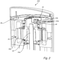
- the actuator arrangement 30 is configured to be controlled by a control unit 20.
- the actuator arrangement 30 is configured to control the flow control arrangement 60.
- the actuator arrangement 30 may be provided as an integral part of the flow control arrangement 60.
- the actuator arrangement 30 may be arranged as a kit of part, wherein the flow control arrangement 60 is a separate part configured to be attached to the actuator arrangement 30.
- the flow control arrangement 60 comprises a first valve member 61 and a second valve member 62.
- the actuator arrangement 30 comprises a housing 30.
- the actuator arrangement 30 comprises a first valve stem 31 and a second valve stem 32.
- the first and second valve stems 31, 32 extend along a longitudinal axis A.
- the first valve stem 31 is connected to and configured to control movement of the first valve member 61 of the flow control arrangement 60.
- the second valve stem 32 is connected to and configured to control movement of the second valve member 62 of the flow control arrangement 60.
- the actuator arrangement 30 further comprises a first electrical motor 33 and a second electrical motor 34.
- the first electrical motor 33 comprises a first rotor part 33a and a first stator part 33b.
- the second electrical motor 34 comprises a second rotor part 34a and a second stator part 34b.
- Each rotor part 33a, 34a is configured to be rotatable about the longitudinal axis A.
- Each stator part 33b, 34b is configured to be fixedly connected to the housing 37 of the actuator arrangement 30.
- the first electrical motor 33 is configured to control movement of the first valve stem 31 and the second electrical motor 34 is configured to control movement of the second valve stem 32.
- the valve stems 31, 32 are configured to move the first and second valve members 61, 62, respectively.
- the flow control arrangement 60 further comprises a first conduit section 65 and a second conduit section 66.
- the first conduit section 65 extends in and is configured to allow a flow of a fluid in a first transverse direction T1.
- the second conduit section 66 extends in and is configured to allow a flow of a fluid in a second transverse direction T2.
- the fluid in the first conduit section 65 and the fluid in the second conduit section 66 may be the same fluid.
- the fluid in the first conduit section 65 and the fluid in the second conduit section 66 may be different fluids.
- the first and second conduits 65, 66 are arranged beside each other as seen along the longitudinal direction L. In this context it may be noted that the conduit sections 65, 66 may have numerous different configurations when it comes to their extension in the transverse direction or directions.
- first and second conduit sections 65, 66 are fluidly interconnected by a connecting opening 67.
- the connecting opening 67 is selectively closable and openable by a double valve formed by the first and second valve members 61, 62.
- the first and second valve members 61, 62 may be movable relative to each other to allow selective cleaning of the first conduit section 65, the first valve member 61, and the first valve seat 63, respectively the second conduit section 66, the second valve member 62, and the second valve seat 64.
- the movement of the first and second valve members 61, 62 being provided by the first and second electrical motor 33, 34, respectively.
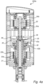
- both the first and second valve members 61, 62 are in a closed position and the double valve is said to be in a closed position.
- the double valve is in the closed position, there is no fluid contact between the first and second conduit section 65, 66 and both the first and second valve members 61, 62 sealing engages its respective valve seat 63, 64.
- the valve seats 63, 64 are best shown in figure 5b .
- both the first and second valve members 61, 62 are in an open position and the double valve is said to be in an open position. Both the first and second valve members 61, 62 have been moved into the first conduit section 65, in the direction L' opposite the longitudinal direction L, such that none of the valve members 61, 62 is in contact with its respective valve seat 63, 64 and thereby allowing fluid to flow between the first and second conduits 65, 66.
- the first and second valve members 61, 62 are sealingly engaging the first and second valve seats 63, 64, respectively, wherein each valve seat 63, 64 extends around the connecting opening 67.
- the first and second valve members 61, 62 are movable relative to each other to allow selective cleaning of the first respectively the second conduit section 65 ,66 of the first respectively the second valve member 61, 62 and of the first respectively the second valve seat 63, 64.
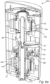
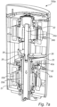
- the actuator arrangement 30 is designed to maneuver the valve members 61, 62 between these four different positions; the closed position shown in figures 1 and 4b , the open position shown in figure 5b , the first cleaning position CP1 shown in figure 6b and the second cleaning position CP2 shown in figure 7b .
- the actuator arrangement 30 is designed to electrically maneuver the valve members 61, 62 by being operated by first respectively the second electrical motor 33, 34.
- an object of this invention is to address an issue related to being able to generally improve the movements of the valve members 61, 62 and especially the movement of the valve members 61, 62 to and from the respective cleaning position CP1, CP2, but also between the open and closed positions, the detailed description will primarily focus on how this is accomplished.
- the first electrical motor 33 is configured to provide a movement of the first valve stem 31 which in turn is configured to provide a movement of the first valve member 61 and thereby exposing the first valve seat 63.
- the first valve stem 31 is configured to be moved in the direction L' opposite the longitudinal direction L in order to move the first valve member 61 in the direction L' opposite the longitudinal direction L.
- the first valve stem 31 is moved by means of the first electrical motor 33 as introduced above.
- the first rotor part 33a of the first electrical motor 33 is configured to transfer at least a portion of a rotational motion, e.g. a first rotational movement, of the first rotor part 33a into a linear motion, e.g. a first movement, of the first valve stem 31.
- the first rotor part 33a is configured to transfer the rotation motion to linear motion of the first valve stem 31 by gripping around a threaded portion of the first valve stem 31 when the first rotor part 33a is rotated about the longitudinal axis A. Thereby, the rotation motion of the first rotor part 33a provides the first movement of the first valve stem 31 in the direction L' opposite the longitudinal direction L into the first cleaning position CP1.
- the first rotor part 33a may form part of a nut of a ball screw-and-nut assembly, wherein the threaded portion of the first valve stem 31 forms ball trucks of the ball screw-and-nut assembly.
- the first rotor part 33a is arranged to transfer rotational motion to linear motion in order to provide for the first valve stem 31 to be moved along the longitudinal axis A with as low internal friction as possible.
- the actuator arrangement 30 further comprises a rotation prevention mechanism.
- the rotation prevention mechanism may be arranged between the first valve stem 31 and an inner support structure forming part of or being the housing 37.
- the rotation prevention mechanism is configured to prevent the first valve stem 31 from rotating in relation to the housing 37.
- the rotation prevention mechanism is configured to prevent the first valve stem 31 from rotating while the first rotor part 33a transfers the rotation motion into the linear motion of the first valve stem 31.
- the rotation prevention mechanism is illustrated as a rotation prevention member 35.
- the rotation prevention member 35 is fixed relative to the first valve stem 31 and is connected to the housing 37. Thereby, the rotation prevention member 35 is rotationally fixed but movable along the longitudinal axis A relative to the housing 37.
- the rotation prevention member 35 may be moved together with the first valve stem 31 along the longitudinal axis A while preventing the first valve stem 31 from rotating relative to the housing 37.
- the first electrical motor 33 is configured to provide a movement of the first valve stem 31 in the longitudinal direction L into the closed position from the first cleaning position in order to provide a complete cleaning cycle. This is provided by rotating the first rotor part 33a in an opposite direction compared to the direction of the first rotational movement, such that the first valve stem 31 is moved in the longitudinal direction L into the closed position. Thereby, the first valve member 61 is moved to the first valve seat 63 such that the first valve member 61 is in contact with the first valve seat 63.
- the second electrical motor 34 is configured to provide a movement of the second valve stem 32 which in turn is configured to provide a movement of the second valve member 62 and thereby exposing the second valve seat 64.
- the second valve stem 32 is configured to be moved in the longitudinal direction L in order to move the second valve member 62 in the longitudinal direction L.
- the second valve stem 32 is moved by means of the second electrical motor 34 as introduced above.
- the second rotor part 34a of the second electrical motor 34 is configured to transfer at least a portion of a rotational motion, e.g. a first rotational movement, of the second rotor part 34a into a linear motion, e.g. a first movement, of the second valve stem 32.
- the second rotor part 34a is configured to transfer the rotation motion to linear motion of the second valve stem 32 by gripping around a threaded portion of the second valve stem 32 when the second rotor part 33a is rotated about the longitudinal axis A. Thereby, the rotation motion of the second rotor part 34a provides the first movement of the second valve stem 32 in the longitudinal direction L into the second cleaning position CP2.
- the second rotor part 34a may form part of a nut of a ball screw-and-nut assembly, wherein the threaded portion of the second valve stem 32 forms ball trucks of the ball screw-and-nut assembly.
- the second rotor part 34a is arranged to transfer rotational motion to linear motion in order to provide for the second valve stem 32 to be moved along the longitudinal axis A with as low internal friction as possible.
- the actuator arrangement 30 further comprises a rotation prevention mechanism.
- the rotation prevention mechanism may be arranged between the second valve stem 32 and an inner support structure forming part of or being the housing 37.
- the rotation prevention mechanism is configured to prevent the second valve stem 32 from rotating in relation to the housing 37.
- the rotation prevention mechanism is configured to prevent the second valve stem 32 from rotating while the second rotor part 34a transfers the rotation motion into the linear motion of the second valve stem 32.
- the rotation prevention mechanism is illustrated as a rotation prevention member 36.
- the rotation prevention member 36 is fixed relative to the second valve stem 32 and is connected to the housing 37. Thereby, the rotation prevention member 36 is rotationally fixed but movable along the longitudinal axis A relative to the housing 37.
- the rotation prevention member 36 may be moved together with the second valve stem 32 along the longitudinal axis A while preventing the second valve stem 32 from rotating relative to the housing 37.
- the second electrical motor 34 is configured to provide a movement of the second valve stem 32 in the direction L' opposite the longitudinal direction L into the closed position from the second cleaning position CP2 in order to provide a complete cleaning cycle. This is provided by rotating the second rotor part 34a in an opposite direction compared to the direction of the first rotational movement, such that the second valve stem 32 is moved in the direction L' opposite the longitudinal direction L into the closed position. Thereby, the second valve member 62 is moved to the second valve seat 64 such that the second valve member 62 is in contact with the second valve seat 64.
- the second valve member 62 may reach the second cleaning position CP2 by being lifted a short distance towards the first conduit section 65 as well.
- This movement is provided in the similar way as discussed above, wherein the second electrical motor 34 is configured to provide a movement of the second valve stem 32 which in turn provides a movement of the second valve member 62.
- the second valve member 62 is moved in the direction L' opposite the longitudinal direction L in order to reach the second cleaning position CP2. In order to be moved from the second cleaning position CP2 back to the closed position the second valve member 62 is moved in the longitudinal direction L into the closed position.
- the first and second valve stems 31, 32 are configured to be moved in the direction L' opposite the longitudinal direction into the open position.
- the first valve stem 31 is moved by means of the first electrical motor 33 as discussed above.
- the second rotor part 34a is configured to grip around the threaded portion of the second valve stem 32 such that a third rotational movement of the second rotor part 34a provides a third movement of the second valve stem 32.
- the third movement of the valve stem 32 is in the direction L' opposite the longitudinal direction L.
- the second valve stem 32 is moved along the direction L' opposite the longitudinal direction L until the second valve member 62 reaches the first valve member 61 such that the first and second valve members 61, 62 are sealingly engaging each other.
- the first rotor part 33a is configured to grip around the threaded portion of the first valve stem 31 such that a third rotational movement of the first rotor part 33a provides a third movement of the first valve stem 31 in the direction L' opposite the longitudinal direction L.
- the first and second valve stems 31, 32 moves in a synchronous motion into the open position while maintaining a sealing engagement between the first and second valve members 61, 62.
- first and second electrical motors 33, 34 are configured to co-operate in order to set the actuator arrangement 30 in the open position.
- the double valve is configured to be moved from the open position to the closed position.
- the first rotor part 33a is configured to grip around the threaded portion of the first valve stem 31 such that a fourth rotational movement of the first rotor part 33a provides a fourth movement of the first valve stem 31.
- the fourth movement of the first valve stem 31 is in the longitudinal direction L.
- the second rotor part 34a is configured to grip around the threaded portion of the second valve stem 32 such that a fourth rotational movement of the second rotor part 34a provides a fourth movement of the second valve stem 32.
- the fourth movement of the second valve stem 32 is in the longitudinal direction L.
- the first and second valve members 61, 62 are sealingly engaging each other during the movement in the longitudinal direction L.
- the first and second valve stems 31, 32 moves in the synchronous motion until the first valve member engages with the first valve seat 63.
- the second valve stem 32 continues to move until the second valve member 62 engages with the second valve seat 64.
- the respective rotational prevent member 35, 36 as introduced above may be moved along the longitudinal axis A while preventing the respective valve stem 31, 32 from rotating relative the housing 37.
- the actuator arrangement 30 further comprises a first electrically operated brake 43 comprising a rotor part 43a and a stator part 43b.
- the rotor part 43a is connected to the rotor part 33a of the first electrical motor 33.
- the rotor part 43a may be connected to the first valve stem 31.
- the stator part 43b is connected to the housing 37.
- the rotor part 43a is configured to be rotatable in relation to the stator part 43b.
- the rotor part 43a may be in contact with the first rotor part 33a of the first electrical motor 33 such that when the electrical motor 33 is running, the rotor part 43a is rotatable together with the first rotor part 33a of the first electrical motor 33.
- the first electrically operated brake 43 further comprises an electromagnetically operated interconnection member 45 being movable between an engaged position and an open position.
- the interconnection member 45 When the interconnection member 45 is in the open position, the rotor part 43a is rotatable relative to the stator part 43b.
- the interconnection member 45 brakes or prevents rotational movement of the rotor part 43a relative to the stator 43b. Thereby, when the interconnection member 45 is in the engaged position, it prevents movement of the first valve stem 31.
- the first electrical motor is running 33, the interconnection member 45 is set in the open position.
- the electrical motor 33 may be configured to operate the first electrically operated brake 43 such that the rotor part 43a is rotatable in relation to the stator part 43b, when the interconnection member 45 is in the open position.
- the interconnection member 45 is preferably set in the engaged position.
- the interconnection member 45 is configured to keep the first valve stem 31 from rotating.
- the interconnection member 45 is preferably mechanically biased into the engaged position.
- the interconnection member 45 is arranged between the rotor part 43a and the stator part 43b. There may be a contact surface formed between the interconnection member 45 and the rotor part 43a which provides for that, when the interconnection member 45 is in the open position, there is a distance formed between interconnection member 45 and the rotor part 43a. In the open position, the interconnection member 45 is not in contact with the rotor part 43a. When the interconnection member 45 is in the engaged position, the interconnection member 45 is moved towards the rotor part 43a such that the interconnection member 45 and the rotor part 43a is in contact. Thereby, it prevents movement of the first valve stem 31.
- the actuator arrangement 30 further comprises second electrically operated brake 44 comprising a rotor part 44a and a stator part 44b.
- the rotor part 44a is connected to the rotor part 34a of the second electrical motor 34.
- the rotor part 44a may be connected to the second valve stem 32.
- the stator part 44b is connected to the housing 37.
- the rotor part 44a is configured to be rotatable in relation to the stator part 44b.
- the rotor part 44a may be in contact with the second rotor part 34a of the second electrical motor 34 such that when the electrical motor 34 is running, the rotor part 44a is rotatable together with the second rotor part 33a of the second electrical motor 33.
- the interconnection member 46 is arranged between the rotor part 44a and the stator part 44b such that the second electrically operated brake 44 may work in the similar way as the first electrically operated brake 43 as discussed above, although having a different design.
- the interconnection member 46 prevents movement of the second valve stem 32.
- the second electrically operated brake 44 may be designed in the similar way as the first electrically operated brake 43 discussed above in connection with figure 3 .
- the actuator arrangement 30 further comprises a backup battery 39.
- the backup battery 39 is configured to, if the first valve stem 31 and/or the second valve stem 32 is in a position different from a normal position, being either the closed position or the open position, and in case of loss of external electrical power, provide electricity to the first electrical motor 33 and/or the second electrical motor 34.
- the electrical motors 33, 34 are configured to set the respective electrically operated brake 43, 44 in the open position and thereby provide a movement of the first valve stem 31 and/or the second valve stem 32 along the longitudinal axis A into the normal position.
- the backup battery 39 is configured to operate the respective electrically operated brake 43, 44 to the engaged position and thereby keep the first valve stem 31 and/or second valve stem 32 in position.
- the method 800 comprises
- the method 800 further comprises
- the cleaning may depend upon the design of the actuator 30 and the second valve stem 32 may be provided to move the second valve member 62 either in the longitudinal direction L or in the direction L' opposite the longitudinal direction L.
- the second valve member 62 is moved from its position in the closed position in the longitudinal direction L such that there is formed a gap between the second valve member 62 and the second valve seat 64.
Landscapes
- Engineering & Computer Science (AREA)
- General Engineering & Computer Science (AREA)
- Mechanical Engineering (AREA)
- Mechanically-Actuated Valves (AREA)
- Electrically Driven Valve-Operating Means (AREA)
Priority Applications (5)
| Application Number | Priority Date | Filing Date | Title |
|---|---|---|---|
| EP21216427.1A EP4202264A1 (fr) | 2021-12-21 | 2021-12-21 | Agencement d'actionneur et procédé de déplacement d'un élément de soupape dans une position de nettoyage |
| US18/722,225 US12510165B2 (en) | 2021-12-21 | 2022-12-20 | Actuator arrangement and a method for moving a valve member into a cleaning position |
| CN202280084252.XA CN118414510A (zh) | 2021-12-21 | 2022-12-20 | 致动器布置以及一种用于将阀构件移动到清洁位置中的方法 |
| PCT/EP2022/086993 WO2023118143A1 (fr) | 2021-12-21 | 2022-12-20 | Agencement d'actionneur et procédé de déplacement d'un élément soupape dans une position de nettoyage |
| EP22843187.0A EP4453452A1 (fr) | 2021-12-21 | 2022-12-20 | Agencement d'actionneur et procédé de déplacement d'un élément soupape dans une position de nettoyage |
Applications Claiming Priority (1)
| Application Number | Priority Date | Filing Date | Title |
|---|---|---|---|
| EP21216427.1A EP4202264A1 (fr) | 2021-12-21 | 2021-12-21 | Agencement d'actionneur et procédé de déplacement d'un élément de soupape dans une position de nettoyage |
Publications (1)
| Publication Number | Publication Date |
|---|---|
| EP4202264A1 true EP4202264A1 (fr) | 2023-06-28 |
Family
ID=78957551
Family Applications (2)
| Application Number | Title | Priority Date | Filing Date |
|---|---|---|---|
| EP21216427.1A Withdrawn EP4202264A1 (fr) | 2021-12-21 | 2021-12-21 | Agencement d'actionneur et procédé de déplacement d'un élément de soupape dans une position de nettoyage |
| EP22843187.0A Pending EP4453452A1 (fr) | 2021-12-21 | 2022-12-20 | Agencement d'actionneur et procédé de déplacement d'un élément soupape dans une position de nettoyage |
Family Applications After (1)
| Application Number | Title | Priority Date | Filing Date |
|---|---|---|---|
| EP22843187.0A Pending EP4453452A1 (fr) | 2021-12-21 | 2022-12-20 | Agencement d'actionneur et procédé de déplacement d'un élément soupape dans une position de nettoyage |
Country Status (4)
| Country | Link |
|---|---|
| US (1) | US12510165B2 (fr) |
| EP (2) | EP4202264A1 (fr) |
| CN (1) | CN118414510A (fr) |
| WO (1) | WO2023118143A1 (fr) |
Families Citing this family (1)
| Publication number | Priority date | Publication date | Assignee | Title |
|---|---|---|---|---|
| DE102024110639A1 (de) * | 2024-04-16 | 2025-10-16 | Gea Tuchenhagen Gmbh | Ventilantrieb für ein Doppelsitzventil sowie Doppelsitzventil |
Citations (2)
| Publication number | Priority date | Publication date | Assignee | Title |
|---|---|---|---|---|
| WO2017042361A1 (fr) | 2015-09-11 | 2017-03-16 | Alfa Laval Corporate Ab | Contrôle de soupape |
| CN111810655A (zh) * | 2020-07-09 | 2020-10-23 | 东莞海特帕沃液压科技有限公司 | 一种电动流量调节阀 |
Family Cites Families (20)
| Publication number | Priority date | Publication date | Assignee | Title |
|---|---|---|---|---|
| US778664A (en) * | 1904-07-25 | 1904-12-27 | Hopkinson And Company Ltd J | Stop-valve. |
| US959618A (en) | 1909-05-06 | 1910-05-31 | George P Carroll | Electric valve. |
| US1047774A (en) * | 1911-09-08 | 1912-12-17 | Eynon Evans Mfg Co | Blow-off valve. |
| US1613183A (en) * | 1925-06-15 | 1927-01-04 | James D Maxwell | Valve |
| CH231313A (de) | 1939-07-28 | 1944-03-15 | Schaltapparate Ag F | Spindelverstelleinrichtung. |
| US2860266A (en) * | 1957-02-06 | 1958-11-11 | American Metal Climax Inc | Linear actuator |
| DE3108778C2 (de) * | 1980-07-22 | 1986-10-16 | Otto Tuchenhagen GmbH & Co KG, 2059 Büchen | Verfahren zur Reinigung beider Sitzflächen eines Doppelsitzventils und Vorrichtung zur Durchführung des Verfahrens |
| DE3134820C2 (de) | 1981-09-03 | 1984-11-29 | Artur 4800 Bielefeld Gronowski | Elektromotorischer Stellgliedantrieb für Ventile o.dgl. |
| DE19548860C1 (de) * | 1995-12-27 | 1997-01-16 | Tetra Laval Holdings & Finance | Absperrventil |
| FR2777626B1 (fr) * | 1998-04-21 | 2000-05-26 | Defontaine | Vanne a clapets et membrane gonflable |
| JP2005048922A (ja) * | 2003-07-31 | 2005-02-24 | Miura Co Ltd | バルブ |
| NO323101B1 (no) | 2004-12-30 | 2007-01-02 | Fmc Kongsberg Subsea As | Feilsikker ventilaktuator |
| DE102006041872B3 (de) * | 2006-08-31 | 2007-12-20 | Saia-Burgess Dresden Gmbh | Gasregel- und Sicherheitsventil für Brenner einer modulierbaren Gasheizeinrichtung |
| DE102009016981A1 (de) | 2009-04-08 | 2010-10-14 | Knorr-Bremse Systeme für Nutzfahrzeuge GmbH | Bistabilventil mit elektromotorischer Betätigung |
| JP6209093B2 (ja) * | 2014-01-27 | 2017-10-04 | 株式会社ミクニ | 流量制御弁 |
| DE202015101759U1 (de) | 2015-04-10 | 2016-07-13 | Bürkert Werke GmbH | Ventillinearantrieb sowie Ventil |
| DE102016203557A1 (de) | 2016-03-03 | 2017-09-07 | Evoguard Gmbh | Kondensatableiter, aseptisches Doppelsitzventil, Verfahren zum Betreiben des Kondensatableiters, und Abfüllanlage |
| US10995862B2 (en) | 2016-03-11 | 2021-05-04 | Karl Dungs Gmbh & Co. Kg | Valve series having different flow capacities and uniform valve actuators |
| US10900583B2 (en) * | 2017-07-17 | 2021-01-26 | Motion Express, Inc. | Explosion proof actuator assembly and servo system |
| JP6858145B2 (ja) * | 2018-02-13 | 2021-04-14 | 太平洋工業株式会社 | 電動弁 |
-
2021
- 2021-12-21 EP EP21216427.1A patent/EP4202264A1/fr not_active Withdrawn
-
2022
- 2022-12-20 WO PCT/EP2022/086993 patent/WO2023118143A1/fr not_active Ceased
- 2022-12-20 EP EP22843187.0A patent/EP4453452A1/fr active Pending
- 2022-12-20 CN CN202280084252.XA patent/CN118414510A/zh active Pending
- 2022-12-20 US US18/722,225 patent/US12510165B2/en active Active
Patent Citations (2)
| Publication number | Priority date | Publication date | Assignee | Title |
|---|---|---|---|---|
| WO2017042361A1 (fr) | 2015-09-11 | 2017-03-16 | Alfa Laval Corporate Ab | Contrôle de soupape |
| CN111810655A (zh) * | 2020-07-09 | 2020-10-23 | 东莞海特帕沃液压科技有限公司 | 一种电动流量调节阀 |
Also Published As
| Publication number | Publication date |
|---|---|
| EP4453452A1 (fr) | 2024-10-30 |
| US12510165B2 (en) | 2025-12-30 |
| WO2023118143A1 (fr) | 2023-06-29 |
| CN118414510A (zh) | 2024-07-30 |
| US20250060040A1 (en) | 2025-02-20 |
Similar Documents
| Publication | Publication Date | Title |
|---|---|---|
| RU2559060C2 (ru) | Электропривод с внутренним механизмом приложения нагрузки | |
| US5611516A (en) | Rotary ball valve with retracting seat | |
| EP2812530B1 (fr) | Dispositif dans un actionneur électromécanique sous-marin et son procédé d'utilisation correspondant | |
| CA2676915C (fr) | Soupape d'etranglement | |
| NO20190378A1 (en) | Electric actuator system and method | |
| US8716963B2 (en) | Actuating device and method of operating an actuating device | |
| US8413573B2 (en) | Helical spline actuators | |
| US12510165B2 (en) | Actuator arrangement and a method for moving a valve member into a cleaning position | |
| US20130255802A1 (en) | Valve and hydraulic controller | |
| EP3017530B1 (fr) | Moteur avec dispositif d'immobilisation de l'arbre | |
| JP2013511006A (ja) | 電動アクチュエータとともに使用するための結合装置 | |
| CN102155524A (zh) | 具有滚珠轴承花键的线性致动器 | |
| WO2013151598A1 (fr) | Soupape et dispositif de commande hydraulique | |
| US20150041689A1 (en) | Fluid-Actuated Butterfly Valve | |
| WO2015080883A1 (fr) | Pompe hydraulique pour un actionneur linéaire | |
| CN108775302B (zh) | 机器人运动关节专用叶片摆动式液压缸 | |
| CN106246439A (zh) | 用于使转子单元的叶片反向的装置 | |
| US10378622B2 (en) | Actuating device with double screw connecting means | |
| JPH0642672A (ja) | ロータリーバルブ用アクチュエーター | |
| CN102155523A (zh) | 用于线性致动器的扭矩反作用波纹管密封 | |
| CN224120739U (zh) | 一种旋转上升的电动执行器 | |
| CN113795679A (zh) | 多端口旋转滑阀 | |
| CN223120679U (zh) | 一种偏心半球阀 | |
| EP3875812B1 (fr) | Agencement de soupape à double siège pour un équipement d'alimentation en fluide | |
| JP2025522129A (ja) | シャフトアセンブリ及び電動弁 |
Legal Events
| Date | Code | Title | Description |
|---|---|---|---|
| PUAI | Public reference made under article 153(3) epc to a published international application that has entered the european phase |
Free format text: ORIGINAL CODE: 0009012 |
|
| STAA | Information on the status of an ep patent application or granted ep patent |
Free format text: STATUS: THE APPLICATION HAS BEEN PUBLISHED |
|
| AK | Designated contracting states |
Kind code of ref document: A1 Designated state(s): AL AT BE BG CH CY CZ DE DK EE ES FI FR GB GR HR HU IE IS IT LI LT LU LV MC MK MT NL NO PL PT RO RS SE SI SK SM TR |
|
| STAA | Information on the status of an ep patent application or granted ep patent |
Free format text: STATUS: THE APPLICATION IS DEEMED TO BE WITHDRAWN |
|
| 18D | Application deemed to be withdrawn |
Effective date: 20240103 |