EP2133233A2 - Agencement de palier de broche pour un mécanisme de réglage de longueur de siège - Google Patents
Agencement de palier de broche pour un mécanisme de réglage de longueur de siège Download PDFInfo
- Publication number
- EP2133233A2 EP2133233A2 EP09006712A EP09006712A EP2133233A2 EP 2133233 A2 EP2133233 A2 EP 2133233A2 EP 09006712 A EP09006712 A EP 09006712A EP 09006712 A EP09006712 A EP 09006712A EP 2133233 A2 EP2133233 A2 EP 2133233A2
- Authority
- EP
- European Patent Office
- Prior art keywords
- spindle
- housing
- nut
- opening
- lateral direction
- Prior art date
- Legal status (The legal status is an assumption and is not a legal conclusion. Google has not performed a legal analysis and makes no representation as to the accuracy of the status listed.)
- Withdrawn
Links
- 238000013016 damping Methods 0.000 claims abstract description 7
- 238000009434 installation Methods 0.000 description 5
- 238000004519 manufacturing process Methods 0.000 description 3
- 229920001971 elastomer Polymers 0.000 description 2
- 239000000806 elastomer Substances 0.000 description 2
- 230000000712 assembly Effects 0.000 description 1
- 238000000429 assembly Methods 0.000 description 1
- 230000001419 dependent effect Effects 0.000 description 1
- 239000013013 elastic material Substances 0.000 description 1
- 238000002955 isolation Methods 0.000 description 1
- 239000000463 material Substances 0.000 description 1
- 239000002184 metal Substances 0.000 description 1
Images



Classifications
-
- B—PERFORMING OPERATIONS; TRANSPORTING
- B60—VEHICLES IN GENERAL
- B60N—SEATS SPECIALLY ADAPTED FOR VEHICLES; VEHICLE PASSENGER ACCOMMODATION NOT OTHERWISE PROVIDED FOR
- B60N2/00—Seats specially adapted for vehicles; Arrangement or mounting of seats in vehicles
- B60N2/02—Seats specially adapted for vehicles; Arrangement or mounting of seats in vehicles the seat or part thereof being movable, e.g. adjustable
- B60N2/04—Seats specially adapted for vehicles; Arrangement or mounting of seats in vehicles the seat or part thereof being movable, e.g. adjustable the whole seat being movable
- B60N2/06—Seats specially adapted for vehicles; Arrangement or mounting of seats in vehicles the seat or part thereof being movable, e.g. adjustable the whole seat being movable slidable
- B60N2/067—Seats specially adapted for vehicles; Arrangement or mounting of seats in vehicles the seat or part thereof being movable, e.g. adjustable the whole seat being movable slidable by linear actuators, e.g. linear screw mechanisms
-
- F—MECHANICAL ENGINEERING; LIGHTING; HEATING; WEAPONS; BLASTING
- F16—ENGINEERING ELEMENTS AND UNITS; GENERAL MEASURES FOR PRODUCING AND MAINTAINING EFFECTIVE FUNCTIONING OF MACHINES OR INSTALLATIONS; THERMAL INSULATION IN GENERAL
- F16H—GEARING
- F16H25/00—Gearings comprising primarily only cams, cam-followers and screw-and-nut mechanisms
- F16H25/18—Gearings comprising primarily only cams, cam-followers and screw-and-nut mechanisms for conveying or interconverting oscillating or reciprocating motions
- F16H25/20—Screw mechanisms
- F16H25/24—Elements essential to such mechanisms, e.g. screws, nuts
-
- F—MECHANICAL ENGINEERING; LIGHTING; HEATING; WEAPONS; BLASTING
- F16—ENGINEERING ELEMENTS AND UNITS; GENERAL MEASURES FOR PRODUCING AND MAINTAINING EFFECTIVE FUNCTIONING OF MACHINES OR INSTALLATIONS; THERMAL INSULATION IN GENERAL
- F16H—GEARING
- F16H25/00—Gearings comprising primarily only cams, cam-followers and screw-and-nut mechanisms
- F16H25/18—Gearings comprising primarily only cams, cam-followers and screw-and-nut mechanisms for conveying or interconverting oscillating or reciprocating motions
- F16H25/20—Screw mechanisms
- F16H25/24—Elements essential to such mechanisms, e.g. screws, nuts
- F16H2025/2445—Supports or other means for compensating misalignment or offset between screw and nut
-
- Y—GENERAL TAGGING OF NEW TECHNOLOGICAL DEVELOPMENTS; GENERAL TAGGING OF CROSS-SECTIONAL TECHNOLOGIES SPANNING OVER SEVERAL SECTIONS OF THE IPC; TECHNICAL SUBJECTS COVERED BY FORMER USPC CROSS-REFERENCE ART COLLECTIONS [XRACs] AND DIGESTS
- Y10—TECHNICAL SUBJECTS COVERED BY FORMER USPC
- Y10T—TECHNICAL SUBJECTS COVERED BY FORMER US CLASSIFICATION
- Y10T74/00—Machine element or mechanism
- Y10T74/18—Mechanical movements
- Y10T74/18568—Reciprocating or oscillating to or from alternating rotary
- Y10T74/18576—Reciprocating or oscillating to or from alternating rotary including screw and nut
- Y10T74/1868—Deflection related
-
- Y—GENERAL TAGGING OF NEW TECHNOLOGICAL DEVELOPMENTS; GENERAL TAGGING OF CROSS-SECTIONAL TECHNOLOGIES SPANNING OVER SEVERAL SECTIONS OF THE IPC; TECHNICAL SUBJECTS COVERED BY FORMER USPC CROSS-REFERENCE ART COLLECTIONS [XRACs] AND DIGESTS
- Y10—TECHNICAL SUBJECTS COVERED BY FORMER USPC
- Y10T—TECHNICAL SUBJECTS COVERED BY FORMER US CLASSIFICATION
- Y10T74/00—Machine element or mechanism
- Y10T74/19—Gearing
- Y10T74/19642—Directly cooperating gears
- Y10T74/19698—Spiral
- Y10T74/19702—Screw and nut
- Y10T74/19716—Non-linear screw
Definitions
- the invention relates to a spindle bearing arrangement for a Wegldicasverstellgetriebe with the preamble features of claim 1.
- a spindle bearing assembly for a Wegl horrsverstellgetriebe having a housing for receiving a worm and a spindle.
- the housing is fastened with a mounting arrangement on a rail of a seat frame, that is to say on a seat-side component.
- the housing has a spindle opening for passing a spindle along a spindle opening axis through the housing.
- Within the housing a kind of spindle nut is arranged, which is designed for passing the spindle.
- the spindle is thereby inserted accurately and without play in the spindle nut.
- the spindle is non-rotatably attached to a bottom-side rail, wherein the rail is in turn firmly connected to a floor panel of a vehicle. Such an arrangement allows adjustment of the spindle along the housing.
- FR 2 749 053 A1 describes a spindle bearing assembly for a Weglteilsverstellgetriebe with a housing which is fixedly connected to a bottom rail and the rail with a floor panel of a vehicle.
- the housing has a spindle opening with an internal thread, wherein a spindle is guided by the internal thread.
- the spindle is rotatably mounted on a seat-side rail. By rotating the spindle, the seat-side rail is moved relative to the stationary housing in the longitudinal direction of the spindle with the spindle together.
- the object of the invention is to improve a spindle bearing arrangement for a Wegl jossverstellgetriebe such that manufacturing tolerances of the spindle and the rails can be better compensated.
- a spindle bearing assembly for a Wegl jossverstellgetriebe which has a housing which with a mounting arrangement on a vehicle-side component or is attachable to a seat-side component, wherein a spindle opening for performing a spindle along a spindle opening axis through the housing performs and wherein an internal thread in the housing in the region of the spindle opening for engaging in a spindle passed through is designed for adjusting the housing and the spindle relative to each other along the spindle opening axis.
- the spindle-bearing assembly is characterized in that the internal thread is formed in a spindle nut and the spindle nut is mounted adjustably in the housing relative to the spindle opening axis.
- the spindle opening may, at least in sections, have a larger inner diameter than a diameter of the spindle.
- the inner diameter is in particular sections in the longitudinal direction of the spindle opening axis by an amount greater that the spindle relative to the spindle opening axis within the spindle opening sufficiently tilted and / or laterally adjustable spindle axis to compensate for installation tolerances, in particular the spindle relative to seat rails can ,
- the spindle nut can be adjustably mounted in the housing in the lateral direction to the spindle opening axis.
- a game formed thereby along the lateral direction can theoretically be arbitrarily large. In practical implementation, however, a limited to a few tenths of a millimeter to a millimeter clearance for adjusting the spindle nut will be sufficient to compensate for installation tolerances of the spindle or other components, in particular a Weglticiansverstellgetriebes.
- transversely to their longitudinal extent bent or bent by installation voltages extending spindles or seat rails can be compensated.
- the spindle nut can be rotatably mounted in the housing at an angle about an axis of rotation extending in a lateral direction to the spindle opening axis.
- Such an angle can theoretically be arbitrarily large. In practical implementation, however, a limited to a few degrees angle is sufficient to compensate for installation tolerances of the spindle or other components, in particular a WeglCodesverstellgetriebes.
- a limited to a few degrees angle is sufficient to compensate for installation tolerances of the spindle or other components, in particular a Weglticiansverstellgetriebes.
- in their longitudinal extent transverse to this lateral direction bent or bent by installation voltages extending spindles or seat rails can be compensated.
- this lateral direction extends in the direction of a fastening element of the fastening arrangement and / or transversely to both the spindle and the seat-side or bottom-side fastening element therethrough.
- inaccuracies of a distance of rails and / or the spindle in seat-side or bottom-side direction can be compensated.
- this lateral direction runs parallel to the extension direction of a fastening element of the fastening arrangement and / or parallel to a planar extension of a fastening element of the fastening arrangement and transversely to the spindle opening axis X.
- inaccuracies of a course of rails and / or the spindle transverse to the seat side or bottom-side direction, ie in a plane parallel to the vehicle floor compensated.
- the internal thread in the spindle nut is preferably designed for rotatable but play-free receiving the spindle.
- the spindle nut is preferably supported by means of at least one damping element elastically in the housing. Noises when adjusting the spindle nut inside the housing are avoided or damped, since the spindle nut and the housing, which are made of a hard material, in particular of metal, can not directly abut each other. In particular, an elastomer or rubber-mounted damping can be provided.
- a spindle bearing assembly for WeglCodesverstellgetriebe to compensate for misalignment of the seat bottom rail and the seat upper rail by a rotatable and / or sliding bearing of the spindle nut in the housing.
- alignment errors can be compensated between the seat bottom rail and the seat upper rail and possibly the spindle guided therein, which can take into account usual manufacturing tolerances in seat rails for longitudinal adjustment.
- alignment errors are compensated, which arise in operation when the seat is loaded beyond a normal load.
- Another advantage is the ease of editing the individual components used.
- another advantageous aspect is the mobility of the housing parts in the rail or the mobility of the spindle in the spindle opening leading through the housing.
- a holder with a rectangular recess and an elastomer for receiving and / or for the isolation of the spindle nut.
- Such a spindle bearing arrangement can be used both in embodiments with a spindle fixedly mounted in a rail and in an embodiment with a spindle rotatably mounted in a seat rail.
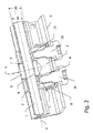
- Fig. 1 and 2 show a spindle 1, which leads through a spindle opening 2 of a housing 3.
- the spindle 1 engages with its outside thread preferably fit exactly into an internal thread 4 of a spindle nut 5 a.
- the spindle nut 5 is formed in a spindle nut receptacle 6, which is formed as a free space within the housing 3.
- the spindle nut receptacle 6 and the spindle nut are dimensioned so that the spindle nut 5 in the housing 1 relative to a spindle opening axis X of the spindle opening 2 adjustable, in particular laterally adjustable and tiltable.
- the spindle opening 2 has an inner diameter dö larger than a diameter ds of the spindle 1.
- the spindle 1 can be laterally adjusted or, in particular, tilted within the spindle opening 2.
- the spindle 1 can thus be tilted both about a point within the spindle nut 5 with a spindle axis relative to the spindle opening axis X, as well as in a lateral direction Y to the spindle opening axis X.
- the spindle opening axis X and the spindle axis are thus not congruent when adjusting the compensation of misalignment in most adjustable positions.
- the spindle nut receiver 6 is preferably designed as a cylindrical space which extends in the lateral direction Y on both sides to the spindle opening axis X in the housing 3.
- the spindle nut 5 inserted in the cylindrical spindle nut receiver 6 is preferably formed as a cylindrical body, so that the spindle nut 5 is rotatable about the rotational axis of the spindle nut 5 extending in the lateral direction Y by an angle ⁇ .
- the spindle nut receptacle 6 is formed so long that the spindle nut 5 along its axis of rotation in the lateral direction Y to the spindle opening axis X can be adjusted.
- the passage opening with the internal thread 4, which passes through the spindle nut 5 for the passage of the spindle 1, is passed transversely to the axis of rotation of the spindle nut 5 through the body of the spindle nut 5.
- the spindle nut receptacle 6 on one side in the direction of the axis of rotation of the spindle nut 5 inserted through the wall of the housing 3 to the outside of the housing 3.
- one or more damping elements 7 made of an elastic material are used in a region between an inside wall of the spindle nut receptacle 6 and an outer wall of the spindle nut 5.
- the damping elements 7 are designed such that the spindle nut 5 within the housing 3 sufficient clearance for adjustment in particular the lateral direction Y and the rotation by a required angle ⁇ reserves.
- a lateral tilting of the spindle 1 relative to the spindle opening axis X is at least partially supported by the use of such damping elements.
- a mounting arrangement which consists of optionally several components.
- a retaining clip 8 surrounds the housing 3 from three sides, wherein the longitudinal extent of the retaining clip 8 leads to its central portion parallel to the spindle opening axis X.
- the lateral legs of the retaining clip 8 thus encompass a part of the housing 3 in an adjustment direction of the spindle 1 relative to a rail 9, to which the retaining clip 8 is fastened by means of screws 10, for example.
- corresponding fastening bores pass through the rail 9 and the retaining clip 8 in alignment with corresponding fastening bores 11, which lead into the body of the housing 3 in order to screw these components together.
- the orientation of the spindle nut receptacle 6 and the spindle nut 5 is selected so that the lateral direction Y leads to the spindle opening axis X transverse to the spindle 1 and transversely to the rail 9, wherein the axis of rotation of the spindle nut 5 while both the spindle 1 and the rail 9 cuts.
- the lateral direction Y thus leads in the direction of a bottom-side fastening element in the form of the rail 9 of the fastening arrangement or to a corresponding seat-side rail in a reverse embodiment.
- the lateral direction Y is transverse to both the spindle and the seat or bottom fastener and therethrough.
- the spindle nut receptacle 6 * and the lateral direction Y * are arranged in the housing 3 *, that the lateral direction Y * parallel to the extension direction of the fastener in the form of the seat rail 9 of the mounting arrangement and transverse to the spindle opening axis X extends.
- the lateral direction Y * runs parallel to a planar extent of the seat-side or bottom-side rail 9.
Landscapes
- Engineering & Computer Science (AREA)
- Mechanical Engineering (AREA)
- General Engineering & Computer Science (AREA)
- Aviation & Aerospace Engineering (AREA)
- Transportation (AREA)
- Seats For Vehicles (AREA)
- Transmission Devices (AREA)
- Mounting Of Bearings Or Others (AREA)
Applications Claiming Priority (1)
| Application Number | Priority Date | Filing Date | Title |
|---|---|---|---|
| DE102008024141A DE102008024141A1 (de) | 2008-05-19 | 2008-05-19 | Spindel-Lageranordnung für ein Sitzlängsverstellgetriebe |
Publications (2)
| Publication Number | Publication Date |
|---|---|
| EP2133233A2 true EP2133233A2 (fr) | 2009-12-16 |
| EP2133233A3 EP2133233A3 (fr) | 2011-08-17 |
Family
ID=40848533
Family Applications (1)
| Application Number | Title | Priority Date | Filing Date |
|---|---|---|---|
| EP09006712A Withdrawn EP2133233A3 (fr) | 2008-05-19 | 2009-05-19 | Agencement de palier de broche pour un mécanisme de réglage de longueur de siège |
Country Status (4)
| Country | Link |
|---|---|
| US (1) | US8176805B2 (fr) |
| EP (1) | EP2133233A3 (fr) |
| CN (1) | CN101585327B (fr) |
| DE (1) | DE102008024141A1 (fr) |
Families Citing this family (10)
| Publication number | Priority date | Publication date | Assignee | Title |
|---|---|---|---|---|
| JP5397236B2 (ja) * | 2010-01-18 | 2014-01-22 | Smc株式会社 | 送りねじ機構 |
| CN103791065B (zh) * | 2014-02-11 | 2015-12-30 | 河海大学常州校区 | 一种可移动支撑架 |
| DE202018105683U1 (de) * | 2018-10-04 | 2020-01-08 | Igus Gmbh | Spindelgetriebe |
| DE102019122928B3 (de) | 2019-06-14 | 2020-10-15 | Adient Engineering and IP GmbH | Längseinsteller und fahrzeugsitz |
| DE102021100886B8 (de) | 2020-10-06 | 2022-06-02 | Adient Engineering and IP GmbH | Längseinsteller und fahrzeugsitz |
| DE102021100601B4 (de) | 2020-10-16 | 2022-10-06 | Adient Us Llc | Längseinsteller, verfahren zur montage eines längseinstellers und fahrzeugsitz |
| DE102021201566A1 (de) * | 2021-02-18 | 2022-08-18 | Brose Fahrzeugteile SE & Co. Kommanditgesellschaft, Coburg | Verstellvorrichtung für eine Fahrzeugbaugruppe mit einem Verstellgetriebe und einem Stützelement |
| CN117693442A (zh) * | 2021-07-26 | 2024-03-12 | 安道拓美国有限责任公司 | 纵向调节器和车辆座椅 |
| DE102021214875A1 (de) | 2021-07-26 | 2023-01-26 | Adient Us Llc | Längseinsteller und fahrzeugsitz |
| WO2023007323A1 (fr) | 2021-07-26 | 2023-02-02 | Adient Us Llc | Dispositif de réglage longitudinal et siège de véhicule |
Citations (2)
| Publication number | Priority date | Publication date | Assignee | Title |
|---|---|---|---|---|
| FR2749053A1 (fr) | 1996-05-24 | 1997-11-28 | Faure Bertrand Equipements Sa | Systeme vis-ecrou pour le reglage en position relative de deux elements mobiles l'un par rapport a l'autre, notamment pour le reglage en position d'un siege d'automobile |
| DE19861100B4 (de) | 1998-04-06 | 2004-09-16 | Brose Fahrzeugteile Gmbh & Co. Kg, Coburg | Spindel- oder Schneckenantrieb für Verstelleinrichtungen in Kraftfahrzeugen |
Family Cites Families (12)
| Publication number | Priority date | Publication date | Assignee | Title |
|---|---|---|---|---|
| US4023431A (en) * | 1975-05-05 | 1977-05-17 | Bettis Corporation | Spring loaded split nut |
| CN85205097U (zh) * | 1985-11-26 | 1987-05-06 | 丁福明 | 螺旋分离式自动消除螺纹间隙机构 |
| DE4000555A1 (de) * | 1990-01-10 | 1991-07-11 | Walter Dipl Ing Dr Ing Mehnert | Getriebeanordnung |
| US5860319A (en) * | 1996-12-19 | 1999-01-19 | Lear Corporation | Reduced noise drive block for vehicle seat adjuster |
| DE19815283C2 (de) * | 1998-04-06 | 2000-07-13 | Brose Fahrzeugteile | Spindelantrieb für Verstelleinrichtungen in Kraftfahrzeugen |
| JP4103212B2 (ja) * | 1998-11-26 | 2008-06-18 | アイシン精機株式会社 | 車両用パワーシートスライド装置 |
| US20030066367A1 (en) * | 2001-10-09 | 2003-04-10 | Ming-Pang Liao | Guiding device for a positional adjustment having a lead-screw |
| EP1331131B1 (fr) * | 2002-01-23 | 2007-09-26 | Delta Kogyo Co., Ltd. | Siège de véhicule ajustable par moteur |
| DE10230514B4 (de) * | 2002-07-06 | 2004-10-14 | Keiper Gmbh & Co. Kg | Längseinsteller für einen Fahrzeugsitz, insbesondere für einen Kraftfahrzeugsitz |
| ITMI20030038A1 (it) * | 2003-01-13 | 2004-07-14 | Elio Cavagna | Dispositivo di movimentazione lineare associato ad una vite senza fine. |
| CN2631825Y (zh) | 2003-08-08 | 2004-08-11 | 宁波双林集团股份有限公司 | 汽车座椅水平驱动器 |
| US6948693B2 (en) | 2003-08-11 | 2005-09-27 | Lear Corporation | Vehicle seat adjuster |
-
2008
- 2008-05-19 DE DE102008024141A patent/DE102008024141A1/de not_active Withdrawn
-
2009
- 2009-04-21 US US12/427,451 patent/US8176805B2/en not_active Expired - Fee Related
- 2009-05-13 CN CN200910140931.0A patent/CN101585327B/zh not_active Expired - Fee Related
- 2009-05-19 EP EP09006712A patent/EP2133233A3/fr not_active Withdrawn
Patent Citations (2)
| Publication number | Priority date | Publication date | Assignee | Title |
|---|---|---|---|---|
| FR2749053A1 (fr) | 1996-05-24 | 1997-11-28 | Faure Bertrand Equipements Sa | Systeme vis-ecrou pour le reglage en position relative de deux elements mobiles l'un par rapport a l'autre, notamment pour le reglage en position d'un siege d'automobile |
| DE19861100B4 (de) | 1998-04-06 | 2004-09-16 | Brose Fahrzeugteile Gmbh & Co. Kg, Coburg | Spindel- oder Schneckenantrieb für Verstelleinrichtungen in Kraftfahrzeugen |
Also Published As
| Publication number | Publication date |
|---|---|
| DE102008024141A1 (de) | 2009-11-26 |
| US8176805B2 (en) | 2012-05-15 |
| EP2133233A3 (fr) | 2011-08-17 |
| CN101585327B (zh) | 2012-09-19 |
| US20090282935A1 (en) | 2009-11-19 |
| CN101585327A (zh) | 2009-11-25 |
Similar Documents
| Publication | Publication Date | Title |
|---|---|---|
| DE102008024141A1 (de) | Spindel-Lageranordnung für ein Sitzlängsverstellgetriebe | |
| EP1076750B1 (fr) | Entraineur reglable servant a la liaison d'une vitre de fenetre a un leve-vitre de vehicule automobile | |
| DE69715591T2 (de) | Justierbarer Doppelfunktions-Anschlag für eine Kraftfahrzeug-Schiebetür | |
| DE112010005253B4 (de) | Verstellvorrichtung mit einem an einer Führungsschiene angeordneten Verstellgetriebe und Verfahren zur Montage einer Verstellvorrichtung | |
| DE10139631B4 (de) | Längseinstellvorrichtung für einen Fahrzeugsitz | |
| EP1835113A2 (fr) | Lève-glace réglable | |
| WO2006027066A1 (fr) | Dispositif de reglage, en particulier pour le siege d'un vehicule a moteur | |
| DE112018000009B4 (de) | Längseinsteller für einen Fahrzeugsitz und Fahrzeugsitz | |
| WO2012027762A1 (fr) | Colonne de direction pour un véhicule automobile | |
| DE19956756C2 (de) | Einstellbarer Mitnehmer für einen Fensterheber einer rahmenlosen Fahrzeugtür | |
| DE102009011120B4 (de) | Einstelleinrichtung für die Fensterscheibe eines Fensterhebers | |
| DE10204610A1 (de) | Fensterheber für eine Kraftfahrzeugtür | |
| DE102019122928B3 (de) | Längseinsteller und fahrzeugsitz | |
| EP4204255B1 (fr) | Système de réglage en longueur, procédé de montage d'un système de réglage en longueur et siège de véhicule | |
| EP4037931B1 (fr) | Système de réglage longitudinal pour siège de véhicule et siège de véhicule | |
| DE102005042190A1 (de) | Scharnieranordnung für einen Deckel eines Kraftfahrzeugs | |
| EP2189558A1 (fr) | Bras de support et de chargement de cylindre supérieur pour un banc d'étirage | |
| DE102005030757B4 (de) | Schiebetüranlage | |
| DE19906669C2 (de) | Vorrichtung zur Befestigung eines Fahrzeugsitzes | |
| DE20219264U1 (de) | Vorrichtung zum Verbinden des Befestigungsbereichs einer Führungsschiene mit dem Türboden einer Fahrzeugtür | |
| DE102007012118B4 (de) | Einstellpuffer für Kraftfahrzeuge | |
| DE202006017178U1 (de) | Werkzeugschlittenanordnung | |
| DE10149003A1 (de) | Vorrichtung zum Fixieren von Karosserieteilen | |
| EP3471982B1 (fr) | Montage en trois points d'une porte coulissante | |
| DE102004027253B4 (de) | Einrichtung zum Einstellen der Lage einer Führungsschiene für eine verstellbare Fensterscheibe eines Fahrzeuges |
Legal Events
| Date | Code | Title | Description |
|---|---|---|---|
| PUAI | Public reference made under article 153(3) epc to a published international application that has entered the european phase |
Free format text: ORIGINAL CODE: 0009012 |
|
| AK | Designated contracting states |
Kind code of ref document: A2 Designated state(s): AT BE BG CH CY CZ DE DK EE ES FI FR GB GR HR HU IE IS IT LI LT LU LV MC MK MT NL NO PL PT RO SE SI SK TR |
|
| PUAL | Search report despatched |
Free format text: ORIGINAL CODE: 0009013 |
|
| AK | Designated contracting states |
Kind code of ref document: A3 Designated state(s): AT BE BG CH CY CZ DE DK EE ES FI FR GB GR HR HU IE IS IT LI LT LU LV MC MK MT NL NO PL PT RO SE SI SK TR |
|
| AX | Request for extension of the european patent |
Extension state: AL BA RS |
|
| RIC1 | Information provided on ipc code assigned before grant |
Ipc: F16H 25/24 20060101ALI20110712BHEP Ipc: F16F 1/38 20060101ALI20110712BHEP Ipc: B60N 2/06 20060101AFI20110712BHEP |
|
| 17P | Request for examination filed |
Effective date: 20120217 |
|
| 17Q | First examination report despatched |
Effective date: 20131011 |
|
| STAA | Information on the status of an ep patent application or granted ep patent |
Free format text: STATUS: THE APPLICATION IS DEEMED TO BE WITHDRAWN |
|
| 18D | Application deemed to be withdrawn |
Effective date: 20131203 |