EP4205589B1 - Impression tridimensionnelle utilisant un élément captif - Google Patents
Impression tridimensionnelle utilisant un élément captif Download PDFInfo
- Publication number
- EP4205589B1 EP4205589B1 EP23157550.7A EP23157550A EP4205589B1 EP 4205589 B1 EP4205589 B1 EP 4205589B1 EP 23157550 A EP23157550 A EP 23157550A EP 4205589 B1 EP4205589 B1 EP 4205589B1
- Authority
- EP
- European Patent Office
- Prior art keywords
- printed
- printing
- shaft
- nozzle
- article
- Prior art date
- Legal status (The legal status is an assumption and is not a legal conclusion. Google has not performed a legal analysis and makes no representation as to the accuracy of the status listed.)
- Active
Links
Images








Classifications
-
- A—HUMAN NECESSITIES
- A43—FOOTWEAR
- A43B—CHARACTERISTIC FEATURES OF FOOTWEAR; PARTS OF FOOTWEAR
- A43B7/00—Footwear with health or hygienic arrangements
- A43B7/14—Footwear with health or hygienic arrangements with foot-supporting parts
-
- A—HUMAN NECESSITIES
- A43—FOOTWEAR
- A43B—CHARACTERISTIC FEATURES OF FOOTWEAR; PARTS OF FOOTWEAR
- A43B13/00—Soles; Sole-and-heel integral units
- A43B13/14—Soles; Sole-and-heel integral units characterised by the constructive form
- A43B13/18—Resilient soles
- A43B13/181—Resiliency achieved by the structure of the sole
-
- A—HUMAN NECESSITIES
- A43—FOOTWEAR
- A43B—CHARACTERISTIC FEATURES OF FOOTWEAR; PARTS OF FOOTWEAR
- A43B13/00—Soles; Sole-and-heel integral units
- A43B13/14—Soles; Sole-and-heel integral units characterised by the constructive form
- A43B13/22—Soles made slip-preventing or wear-resisting, e.g. by impregnation or spreading a wear-resisting layer
-
- A—HUMAN NECESSITIES
- A43—FOOTWEAR
- A43B—CHARACTERISTIC FEATURES OF FOOTWEAR; PARTS OF FOOTWEAR
- A43B23/00—Uppers; Boot legs; Stiffeners; Other single parts of footwear
-
- A—HUMAN NECESSITIES
- A43—FOOTWEAR
- A43B—CHARACTERISTIC FEATURES OF FOOTWEAR; PARTS OF FOOTWEAR
- A43B23/00—Uppers; Boot legs; Stiffeners; Other single parts of footwear
- A43B23/02—Uppers; Boot legs
-
- A—HUMAN NECESSITIES
- A43—FOOTWEAR
- A43B—CHARACTERISTIC FEATURES OF FOOTWEAR; PARTS OF FOOTWEAR
- A43B23/00—Uppers; Boot legs; Stiffeners; Other single parts of footwear
- A43B23/02—Uppers; Boot legs
- A43B23/0245—Uppers; Boot legs characterised by the constructive form
-
- A—HUMAN NECESSITIES
- A43—FOOTWEAR
- A43B—CHARACTERISTIC FEATURES OF FOOTWEAR; PARTS OF FOOTWEAR
- A43B23/00—Uppers; Boot legs; Stiffeners; Other single parts of footwear
- A43B23/02—Uppers; Boot legs
- A43B23/04—Uppers made of one piece; Uppers with inserted gussets
- A43B23/042—Uppers made of one piece
-
- A—HUMAN NECESSITIES
- A43—FOOTWEAR
- A43B—CHARACTERISTIC FEATURES OF FOOTWEAR; PARTS OF FOOTWEAR
- A43B23/00—Uppers; Boot legs; Stiffeners; Other single parts of footwear
- A43B23/24—Ornamental buckles; Other ornaments for shoes without fastening function
-
- A—HUMAN NECESSITIES
- A43—FOOTWEAR
- A43B—CHARACTERISTIC FEATURES OF FOOTWEAR; PARTS OF FOOTWEAR
- A43B3/00—Footwear characterised by the shape or the use
- A43B3/26—Footwear characterised by the shape or the use adjustable as to length or size
-
- A—HUMAN NECESSITIES
- A43—FOOTWEAR
- A43C—FASTENINGS OR ATTACHMENTS OF FOOTWEAR; LACES IN GENERAL
- A43C1/00—Shoe lacing fastenings
-
- A—HUMAN NECESSITIES
- A43—FOOTWEAR
- A43C—FASTENINGS OR ATTACHMENTS OF FOOTWEAR; LACES IN GENERAL
- A43C1/00—Shoe lacing fastenings
- A43C1/04—Shoe lacing fastenings with rings or loops
-
- A—HUMAN NECESSITIES
- A43—FOOTWEAR
- A43C—FASTENINGS OR ATTACHMENTS OF FOOTWEAR; LACES IN GENERAL
- A43C1/00—Shoe lacing fastenings
- A43C1/06—Shoe lacing fastenings tightened by draw-strings
-
- A—HUMAN NECESSITIES
- A43—FOOTWEAR
- A43C—FASTENINGS OR ATTACHMENTS OF FOOTWEAR; LACES IN GENERAL
- A43C11/00—Other fastenings specially adapted for shoes
- A43C11/14—Clamp fastenings, e.g. strap fastenings; Clamp-buckle fastenings; Fastenings with toggle levers
-
- A—HUMAN NECESSITIES
- A43—FOOTWEAR
- A43C—FASTENINGS OR ATTACHMENTS OF FOOTWEAR; LACES IN GENERAL
- A43C11/00—Other fastenings specially adapted for shoes
- A43C11/16—Fastenings secured by wire, bolts, or the like
-
- A—HUMAN NECESSITIES
- A43—FOOTWEAR
- A43C—FASTENINGS OR ATTACHMENTS OF FOOTWEAR; LACES IN GENERAL
- A43C5/00—Eyelets
-
- A—HUMAN NECESSITIES
- A43—FOOTWEAR
- A43C—FASTENINGS OR ATTACHMENTS OF FOOTWEAR; LACES IN GENERAL
- A43C7/00—Holding-devices for laces
-
- B—PERFORMING OPERATIONS; TRANSPORTING
- B29—WORKING OF PLASTICS; WORKING OF SUBSTANCES IN A PLASTIC STATE IN GENERAL
- B29C—SHAPING OR JOINING OF PLASTICS; SHAPING OF MATERIAL IN A PLASTIC STATE, NOT OTHERWISE PROVIDED FOR; AFTER-TREATMENT OF THE SHAPED PRODUCTS, e.g. REPAIRING
- B29C64/00—Additive manufacturing, i.e. manufacturing of three-dimensional [3D] objects by additive deposition, additive agglomeration or additive layering, e.g. by 3D printing, stereolithography or selective laser sintering
-
- B—PERFORMING OPERATIONS; TRANSPORTING
- B29—WORKING OF PLASTICS; WORKING OF SUBSTANCES IN A PLASTIC STATE IN GENERAL
- B29C—SHAPING OR JOINING OF PLASTICS; SHAPING OF MATERIAL IN A PLASTIC STATE, NOT OTHERWISE PROVIDED FOR; AFTER-TREATMENT OF THE SHAPED PRODUCTS, e.g. REPAIRING
- B29C64/00—Additive manufacturing, i.e. manufacturing of three-dimensional [3D] objects by additive deposition, additive agglomeration or additive layering, e.g. by 3D printing, stereolithography or selective laser sintering
- B29C64/10—Processes of additive manufacturing
- B29C64/106—Processes of additive manufacturing using only liquids or viscous materials, e.g. depositing a continuous bead of viscous material
-
- B—PERFORMING OPERATIONS; TRANSPORTING
- B29—WORKING OF PLASTICS; WORKING OF SUBSTANCES IN A PLASTIC STATE IN GENERAL
- B29C—SHAPING OR JOINING OF PLASTICS; SHAPING OF MATERIAL IN A PLASTIC STATE, NOT OTHERWISE PROVIDED FOR; AFTER-TREATMENT OF THE SHAPED PRODUCTS, e.g. REPAIRING
- B29C64/00—Additive manufacturing, i.e. manufacturing of three-dimensional [3D] objects by additive deposition, additive agglomeration or additive layering, e.g. by 3D printing, stereolithography or selective laser sintering
- B29C64/10—Processes of additive manufacturing
- B29C64/106—Processes of additive manufacturing using only liquids or viscous materials, e.g. depositing a continuous bead of viscous material
- B29C64/112—Processes of additive manufacturing using only liquids or viscous materials, e.g. depositing a continuous bead of viscous material using individual droplets, e.g. from jetting heads
-
- B—PERFORMING OPERATIONS; TRANSPORTING
- B29—WORKING OF PLASTICS; WORKING OF SUBSTANCES IN A PLASTIC STATE IN GENERAL
- B29C—SHAPING OR JOINING OF PLASTICS; SHAPING OF MATERIAL IN A PLASTIC STATE, NOT OTHERWISE PROVIDED FOR; AFTER-TREATMENT OF THE SHAPED PRODUCTS, e.g. REPAIRING
- B29C64/00—Additive manufacturing, i.e. manufacturing of three-dimensional [3D] objects by additive deposition, additive agglomeration or additive layering, e.g. by 3D printing, stereolithography or selective laser sintering
- B29C64/30—Auxiliary operations or equipment
-
- B—PERFORMING OPERATIONS; TRANSPORTING
- B29—WORKING OF PLASTICS; WORKING OF SUBSTANCES IN A PLASTIC STATE IN GENERAL
- B29D—PRODUCING PARTICULAR ARTICLES FROM PLASTICS OR FROM SUBSTANCES IN A PLASTIC STATE
- B29D22/00—Producing hollow articles
-
- B—PERFORMING OPERATIONS; TRANSPORTING
- B29—WORKING OF PLASTICS; WORKING OF SUBSTANCES IN A PLASTIC STATE IN GENERAL
- B29D—PRODUCING PARTICULAR ARTICLES FROM PLASTICS OR FROM SUBSTANCES IN A PLASTIC STATE
- B29D35/00—Producing footwear
- B29D35/12—Producing parts thereof, e.g. soles, heels, uppers, by a moulding technique
-
- B—PERFORMING OPERATIONS; TRANSPORTING
- B33—ADDITIVE MANUFACTURING TECHNOLOGY
- B33Y—ADDITIVE MANUFACTURING, i.e. MANUFACTURING OF THREE-DIMENSIONAL [3D] OBJECTS BY ADDITIVE DEPOSITION, ADDITIVE AGGLOMERATION OR ADDITIVE LAYERING, e.g. BY 3D PRINTING, STEREOLITHOGRAPHY OR SELECTIVE LASER SINTERING
- B33Y10/00—Processes of additive manufacturing
-
- B—PERFORMING OPERATIONS; TRANSPORTING
- B33—ADDITIVE MANUFACTURING TECHNOLOGY
- B33Y—ADDITIVE MANUFACTURING, i.e. MANUFACTURING OF THREE-DIMENSIONAL [3D] OBJECTS BY ADDITIVE DEPOSITION, ADDITIVE AGGLOMERATION OR ADDITIVE LAYERING, e.g. BY 3D PRINTING, STEREOLITHOGRAPHY OR SELECTIVE LASER SINTERING
- B33Y80/00—Products made by additive manufacturing
-
- A—HUMAN NECESSITIES
- A43—FOOTWEAR
- A43D—MACHINES, TOOLS, EQUIPMENT OR METHODS FOR MANUFACTURING OR REPAIRING FOOTWEAR
- A43D2200/00—Machines or methods characterised by special features
- A43D2200/60—Computer aided manufacture of footwear, e.g. CAD or CAM
-
- B—PERFORMING OPERATIONS; TRANSPORTING
- B29—WORKING OF PLASTICS; WORKING OF SUBSTANCES IN A PLASTIC STATE IN GENERAL
- B29C—SHAPING OR JOINING OF PLASTICS; SHAPING OF MATERIAL IN A PLASTIC STATE, NOT OTHERWISE PROVIDED FOR; AFTER-TREATMENT OF THE SHAPED PRODUCTS, e.g. REPAIRING
- B29C64/00—Additive manufacturing, i.e. manufacturing of three-dimensional [3D] objects by additive deposition, additive agglomeration or additive layering, e.g. by 3D printing, stereolithography or selective laser sintering
- B29C64/10—Processes of additive manufacturing
- B29C64/106—Processes of additive manufacturing using only liquids or viscous materials, e.g. depositing a continuous bead of viscous material
- B29C64/118—Processes of additive manufacturing using only liquids or viscous materials, e.g. depositing a continuous bead of viscous material using filamentary material being melted, e.g. fused deposition modelling [FDM]
-
- B—PERFORMING OPERATIONS; TRANSPORTING
- B29—WORKING OF PLASTICS; WORKING OF SUBSTANCES IN A PLASTIC STATE IN GENERAL
- B29K—INDEXING SCHEME ASSOCIATED WITH SUBCLASSES B29B, B29C OR B29D, RELATING TO MOULDING MATERIALS OR TO MATERIALS FOR MOULDS, REINFORCEMENTS, FILLERS OR PREFORMED PARTS, e.g. INSERTS
- B29K2101/00—Use of unspecified macromolecular compounds as moulding material
- B29K2101/12—Thermoplastic materials
-
- B—PERFORMING OPERATIONS; TRANSPORTING
- B29—WORKING OF PLASTICS; WORKING OF SUBSTANCES IN A PLASTIC STATE IN GENERAL
- B29K—INDEXING SCHEME ASSOCIATED WITH SUBCLASSES B29B, B29C OR B29D, RELATING TO MOULDING MATERIALS OR TO MATERIALS FOR MOULDS, REINFORCEMENTS, FILLERS OR PREFORMED PARTS, e.g. INSERTS
- B29K2995/00—Properties of moulding materials, reinforcements, fillers, preformed parts or moulds
- B29K2995/0037—Other properties
- B29K2995/0082—Flexural strength; Flexion stiffness
-
- B—PERFORMING OPERATIONS; TRANSPORTING
- B29—WORKING OF PLASTICS; WORKING OF SUBSTANCES IN A PLASTIC STATE IN GENERAL
- B29L—INDEXING SCHEME ASSOCIATED WITH SUBCLASS B29C, RELATING TO PARTICULAR ARTICLES
- B29L2031/00—Other particular articles
- B29L2031/48—Wearing apparel
- B29L2031/50—Footwear, e.g. shoes or parts thereof
- B29L2031/505—Uppers
-
- B—PERFORMING OPERATIONS; TRANSPORTING
- B29—WORKING OF PLASTICS; WORKING OF SUBSTANCES IN A PLASTIC STATE IN GENERAL
- B29L—INDEXING SCHEME ASSOCIATED WITH SUBCLASS B29C, RELATING TO PARTICULAR ARTICLES
- B29L2031/00—Other particular articles
- B29L2031/727—Fastening elements
Definitions
- the present embodiments relate generally to articles of apparel.
- Three-dimensional printing systems and methods may be associated with various technologies including fused deposition modeling (FDM), electron beam freeform fabrication (EBF), selective laser sintering (SLS) as well as other kinds of three-dimensional printing technologies.
- FDM fused deposition modeling
- EBF electron beam freeform fabrication
- SLS selective laser sintering
- US 2015/099087 A1 describes a printed encapsulation method and part. Another aspect uses a three-dimensional printing machine to emit material from an inkjet printing head to build up material attached to an insert.
- WO 2014/209994 A2 describes that a printed 3D functional part includes a 3D structure comprising a structural material, and at least one functional electronic device is at least partially embedded in the 3D structure.
- US 2013/071599 A1 describes that a method serves to produce a three-dimensional object by additive construction in direct construction sequence from solidifiable material, which is either present in the starting state in a fluid phase or can be liquefied, where multiple material components are discharged alternately in a programmable manner by means of multiple discharge units and configure different parts of the object joined to one another as a result of the discharge.
- the claimed invention is directed to an article of apparel as defined in claim 1.
- FIG. 1 is a schematic view of an embodiment of a three-dimensional printing system 100, also referred to simply as printing system 100 hereafter.
- FIG. 1 also illustrates several exemplary articles 130 that may be used with printing system 100.
- FIG. 1 depicts several elements 194 that may be incorporated, placed, or otherwise used during printing.
- printing system 100 may further comprise a printing device 102, a computing system 104, and a network 106.
- Structures may be formed and attached to an article using an additive manufacturing process, also referred to as three-dimensional printing (or simply “printing” hereafter).
- additive manufacturing also referred to as “three-dimensional printing” refers to any device and technology for making a three-dimensional object through an additive process where layers of material are successively laid down under the control of a computer.
- outer surface refers to the surface of a component that would be facing away from the foot when worn by a wearer.
- inner surface refers to the surface of a component that is facing inward, or the surface that faces toward the foot when worn by a wearer.
- printing system 100 can include provisions for facilitating the alignment of a printed design or graphic onto an article. In some embodiments, it may be useful to provide a user with a way of aligning an article with printing system 100 so as to ensure a graphic is printed in the desired portion of the article. In particular, printing system 100 may include provisions for programming the orientation of an article with print device 102 in such a way as to accommodate articles of various types, shapes, curves, and sizes.
- nozzle assembly 116 is associated with a first actuating system 114.
- First actuating system 114 may include various components, devices and systems that facilitate the motion of nozzle assembly 116 within housing 110.
- first actuating system 114 may include provisions to move nozzle assembly 116 in any horizontal direction.
- Horizontal directions can include longitudinal directions, referred to herein as a third direction 164, and/or lateral directions, also referred to herein as a second direction 162, or any other direction lying along the horizontal plane.
- First actuating system 114 may also include provisions to move nozzle assembly 116 in any vertical direction, identified herein as a first direction 160.
- first actuating system 114 may include one or more tracks, rails, and/or similar provisions to hold nozzle assembly 116 at various positions and/or orientations within housing 110.
- Embodiments may also include any kinds of motors, such as a stepper motor or a servo motor, to move nozzle assembly 116 along a track or rail, and/or to move one or more tracks or rails relative to one another.
- An actuating system can be configured to move a nozzle in one or more directions.
- an actuating system could move a nozzle in a single linear direction.
- an actuating system could move a nozzle in at least two perpendicular directions.
- an actuating system could move a nozzle in three perpendicular directions.
- first actuating system 114 may be configured to move nozzle 118 in first direction 160, second direction 162 and third direction 164. As seen in FIG.
- first direction 160 may be associated with a vertical direction of housing 110
- second direction 162 and third direction 164 may be associated with horizontal directions of housing 110 (e.g., length and width directions).
- actuating system capable of moving a nozzle through three independent x-y-z or Cartesian directions
- other embodiments may be configured to move a nozzle in three independent directions associated with a non-Cartesian coordinate system (e.g., a spherical coordinate system, a cylindrical coordinate system, etc.).
- a actuating system could move a nozzle through three different directions that may not be orthogonal (e.g., directions of an oblique coordinate system).
- first direction 160 is approximately normal to a surface, such as a print surface 148.
- a direction is approximately normal to a surface when it is within 10 degrees from perpendicular to the surface.
- first direction 160 is approximately normal to print surface 148.
- a print surface may correspond to the surface where a nozzle is printing.
- the print surface is associated with a surface of tray 112.
- print surface 148 is illustrated as the side of tray 112 that faces upward toward nozzle assembly 116.
- print surface 148 may comprise the surface or side of an article or object that is printed upon by nozzle 118.
- Print surface 148 may be generally flat, or it may be substantially curved and include contours.
- print surface 148 may be the side or surface of an object or article that is generally normal to first direction 160.
- print surface 148 may refer to the surface of an article that is attached to a printing material such as a thread or other material extruded or otherwise discharged or emitted from nozzle 118.
- Second actuating system 190 may include various components, devices and systems that facilitate the motion of elements 194 within housing 110.
- second actuating system 190 may include provisions to move elements 194 in any horizontal direction and/or vertical direction to facilitate the position of elements 194 during printing.
- embodiments of second actuating system 190 may include one or more tracks, rails, and/or similar provisions to hold elements 194 at various positions and/or orientations within housing 110.
- Embodiments may also include any kinds of motors, such as a stepper motor or a servo motor, to move elements 194 along a track or rail, and/or to move one or more tracks or rails relative to one another.
- second actuating system 190 there may be a securing device 192, such as a clamp or other adjustable gripping member, in second actuating system 190.
- Securing device 192 can provide a means of attachment between second actuating system 190 and elements 194.
- portions of second actuating system 190 may be positioned in various locations within printing system 100.
- second actuating system 190 may include provisions for removing elements 194 from printed structures.
- second actuating system 190 can be configured to move an element in one or more directions.
- an actuating system could move an element in a single linear direction.
- an actuating system could move an element in at least two perpendicular directions.
- an actuating system could move an element in three perpendicular directions.
- second actuating system 190 may be configured to move elements 194 in a first direction 160, a second direction 162 and a third direction 164. As seen in FIG.
- first direction 160 may be associated with a vertical direction of housing 110
- second direction 162 and third direction 164 may be associated with horizontal directions of housing 110 (e.g., length and width directions).
- actuating system capable of moving an element through three independent x-y-z or Cartesian directions
- other embodiments may be configured to move an element in three independent directions associated with a non-Cartesian coordinate system (e.g., a spherical coordinate system, a cylindrical coordinate system, etc.).
- an actuating system could move an element through three different directions that may not be orthogonal (e.g., directions of an oblique coordinate system).
- printing system 100 may selectively move the element using second actuating system 190 or another mechanism.
- printing system 100 simultaneously moves elements 194 in three directions.
- printing system 100 may move elements 194 in first direction 160 away from tray 112 while simultaneously moving elements 194 in second direction 162 and/or in third direction 164 in a direction generally parallel to tray 112.
- a position along a direction is maintained while printing system 100 selectively moves elements 194 in another direction.
- printing system 100 may move elements 194 in first direction 160 to or away from tray 112 while simultaneously maintaining a base position of elements 194 in second direction 162 and in third direction 164 along print surface 148.
- printing system 100 may maintain a print distance 216 from elements 194 in first direction 160 while simultaneously moving elements 194 parallel to print surface 148.
- printing system 100 may maintain a print distance 216 from elements 194 in first direction 160 while simultaneously moving elements 194 in second direction 162 and/or third direction 164.
- first actuating system 114 and/or second actuating system 190 can be operated manually by a user.
- some embodiments could include motors and/or other provisions for automatically driving nozzle 118 to various positions along one or more tracks.
- the position or speed of nozzle 118 and/or elements 194 could be adjusted using controls provided in printing system 100, or using an associated system, such as computing system 104, which is discussed in further detail below.
- first actuating system 114 is shown schematically as including several tracks or rails, but the particular configuration and number of parts comprising first actuating system 114 may vary from one embodiment to another.
- computing system 104 may comprise a central processing device 185, a viewing interface 186 (e.g., a monitor or screen), input devices 187 (e.g., keyboard and mouse), and software for designing a computer-aided design ("CAD") representation 189 of a printed structure.
- CAD computer-aided design
- the CAD representation 189 of a printed structure may include not only information about the geometry of the structure, but also information related to the materials required to print various portions of the structure.
- computing system 104 may be in direct contact with printing device 102 via network 106.
- Network 106 may include any wired or wireless provisions that facilitate the exchange of information between computing system 104 and printing device 102.
- network 106 may further include various components such as network interface controllers, repeaters, hubs, bridges, switches, routers, modems and firewalls.
- network 106 may be a wireless network that facilitates wireless communication between two or more systems, devices and/or components of printing system 100. Examples of wireless networks include, but are not limited to: wireless personal area networks (including, for example, Bluetooth), wireless local area networks (including networks utilizing the IEEE 802.11 WLAN standards), wireless mesh networks, mobile device networks as well as other kinds of wireless networks.
- network 106 could be a wired network including networks whose signals are facilitated by twister pair wires, coaxial cables, and optical fibers. In still other cases, a combination of wired and wireless networks and/or connections could be used.
- Printing system 100 may be operated as follows to provide one or more structures that have been formed using a 3D printing, or additive, process.
- Computing system 104 may be used to design a structure. This may be accomplished using some type of CAD software, or other kind of software.
- the design may then be transformed into information that can be interpreted by printing device 102 (or a related print server in communication with printing device 102).
- the design may be converted to a 3D printable file, such as a stereolithography file (STL file).
- STL file stereolithography file
- an article Before printing, an article may be placed onto tray 112 or may be secured using second actuating system 190.
- printing device 102 may begin depositing material onto the article. This may be accomplished by moving nozzle 118 (using first actuating system 114) to build up layers of a structure using deposited material. In embodiments where fused filament fabrication is used, material extruded from nozzle 118 may be heated so as to increase the pliability of the heat moldable material as it is deposited.
- printing system 100 may use a tack and drag print method.
- still other embodiments could incorporate a combination of fused filament fabrication and another type of 3D printing technique to achieve desired results for a particular printed structure or part.
- printing device 102 may use a variety of different materials for forming 3D parts, including, but not limited to: thermoplastics (e.g., polyactic acid and acrylonitrile butadiene styrene), high density polyethylene, eutectic metals, rubber, clays (including metal clays), Room Temperature Vulcanizing silicone (RTV silicone), porcelain, as well as possibly other kinds of materials known in the art.
- thermoplastics e.g., polyactic acid and acrylonitrile butadiene styrene
- high density polyethylene eutectic metals
- rubber eutectic metals
- clays including metal clays
- RTV silicone Room Temperature Vulcanizing silicone
- porcelain room Temperature Vulcanizing silicone
- any two or more of the materials disclosed above could be used.
- printing device 102 may extrude, discharge or use a material or thread composition.
- additive printing systems used with the embodiments can make use of any printable materials.
- the term "printable material” or “print material” is intended to encompass any materials that may be printed, ejected, emitted, or otherwise deposited during an additive manufacturing process.
- Such materials can include, but are not limited to, thermoplastics (e.g., PLA and ABS) and thermoplastic powders, high-density polyurethylene, eutectic metals, rubber, modeling clay, plasticine, RTV silicone, porcelain, metal clay, ceramic materials, plaster, and photopolymers, as well as possibly other materials known for use in 3D printing.
- printed structures may be printed directly onto one or more articles 130, or a portion of articles 130.
- articles is intended to include articles of apparel (e.g., shirts, pants, footwear, etc.), as well as other objects, textiles, or materials.
- article of footwear and footwear include any footwear and any materials associated with footwear, including an upper, lacing elements, and sole structures, and may also be applied to a variety of athletic foqtwear types, including baseball shoes, basketball shoes, cross-training shoes, cycling shoes, football shoes, tennis shoes, soccer shoes, and hiking boots, for example.
- articles 130 comprise exemplary articles that may receive a printed structure directly from printing device 102, including an upper 134 or a shirt 136.
- the disclosed embodiments may further be equally applied to any article of apparel or equipment that may receive 3D printing.
- article of apparel may refer to any apparel or clothing, including any article of footwear, as well as hats, caps, shirts, jerseys, jackets, socks, shorts, pants, undergarments, athletic support garments, gloves, wrist/arm bands, sleeves, headbands, any knit material, any woven material, any nonwoven material, etc.
- Other examples of articles include, but are not limited to: shin guards, knee pads, elbow pads, shoulder pads, as well as any other type of protective equipment.
- the article could be another type of article that is not configured to be worn, including, but not limited to: balls, bags, purses, backpacks, as well as other articles that may not be worn.
- printing device 102 may be capable of printing onto the surfaces of various kinds of materials. Specifically, in some cases, printing device 102 may be capable of printing onto the surfaces of various materials such as a textile, a natural fabric, a synthetic fabric, a knit, a woven material, a nonwoven material, a mesh, a leather, a synthetic leather, a polymer, a rubber, and a foam, or any combination of them, without the need for a release layer interposed between a substrate and the bottom of the printed material, and without the need for a perfectly or near-perfectly flat substrate surface on which to print.
- various materials such as a textile, a natural fabric, a synthetic fabric, a knit, a woven material, a nonwoven material, a mesh, a leather, a synthetic leather, a polymer, a rubber, and a foam, or any combination of them, without the need for a release layer interposed between a substrate and the bottom of the printed material, and without the need for a perfectly or near-perfectly flat substrate
- the disclosed methods may include printing a resin, acrylic, thermoplastic material or ink material onto a fabric, for example a knit material, where the material is adhered/bonded to the fabric and where the material does not generally delaminate when flexed, rolled, worked, or subject to additional assembly processes/steps.
- a fabric may be used to refer generally to materials chosen from any textile, natural fabric, synthetic fabric, knit, woven material, nonwoven material, mesh, leather, synthetic leather, polymers, rubbers, and foam.
- printing device 102 may use printing device 102 to print structures directly onto the surface of a material
- other embodiments may include steps of printing a structure onto a tray or release paper, and then joining the printed structure to an article in a separate step.
- printed structures need not be printed directly to the surface of articles 130.
- printing device 102 may be configured to print one or more structures that incorporate or utilize one or more elements 194 (for example, elements may be placed within or along the printed structure).
- Elements 194 comprise exemplary elements that may be inserted, disposed, laid adjacent to, placed in contact with, or otherwise incorporated into at least a portion of a printed structure.
- elements 194 may include a lacing element 132 or a shaft 196.
- Elements 194 may also include other objects or substrates which can vary in size, dimension, geometry, material composition, rigidity, texture and other properties.
- An element for purposes of this disclosure may include but are not limited to cords, cables, laces, shafts, cylinders, tubes, strands, wire, or any other object or material that can be disposed adjacent to printed materials or a printed structure. Elements 194 will be discussed in detail further below.
- printing device 102 may be configured to print directly onto various articles 130.
- a first article 204 is depicted.
- First article 204 comprises an unassembled upper for an article of footwear.
- first article 204 includes a forefoot region 210, a midfoot region 212, and a heel region 214, as described above.
- first article 204 includes a lateral side 206 and a medial side 208.
- first article 204 can include any type of surface, object, or material.
- first article 204 may be an upper or a shirt, for example.
- first article 204 is a portion of an upper.
- print surface 148 the surface of the article or material upon which printing occurs
- nozzle 118 is configured to emit, discharge, or extrude various materials.
- the printed material may be discharged, ejected or otherwise emitted via nozzle 118 in the form of droplets 202.
- droplets 202 may vary depending on the actual material ejected or otherwise emitted from nozzle 118.
- droplets 202 may thus be any viscosity liquid material, or even a semi-solid material.
- droplets 202 may be any desired material or phase of material suitable for use in printing system 100.
- the nozzle system employed may be equivalent or identical to that used in inkjet printing systems, such as piezo inkjet systems.
- a nozzle may be associated with a piezoelectric inkjet head.
- second layer 402 has been completed, forming a first composite layer 500 comprising first layer 400 and second layer 402, while a third layer 502 is being formed.
- the process depicted in FIGS. 3-5 may be repeated multiple times to build a structure of desired thickness, shape, and/or area.
- first partial structure 600 comprising multiple layers of printed material is depicted.
- First partial structure 600 includes a first recess 602.
- first recess 602 is formed by adding multiple layers in a step pattern that comprise the portion of first partial structure 600 which include first recess 602.
- the edges of first recess 602 are a plurality of steps 610 along the surface of first partial structure 600, including a first step 606 and a second step 608.
- various portions of a printed structure may include differences in thickness, area, material, shape, design in order to form recesses, openings, or other features.
- first recess 602 may be formed at an earlier point in printing, or at a later point.
- a printed structure may incorporate various elements.
- first partial structure 600 is shown adjacent a second lace 700.
- Second lace 700 may be inserted, placed, disposed, laid down along or otherwise provided to first partial structure 600 at different points of the printing process.
- second lace 700 may be presented before first recess 602 is formed.
- second lace 700 may be provided during or after the formation of first recess 602.
- second lace 700 has been placed along recess surface 704 of first partial structure 600.
- additional layers are laid over first partial structure 600, as well as second lace 700, forming a second partial structure 902.
- Second partial structure 902 includes a first tunnel 900, formed in part with previously formed first recess 602.
- a portion of second lace 700 is now covered by or enclosed within first tunnel 900 of second partial structure 902.
- FIG. 10 printing is completed, and a third structure 1000 has been formed.
- Second lace 700 is positioned such that a portion of second lace 700 is disposed entirely within an interior portion of third structure 1000.
- second lace 700 may be attached within first tunnel 900, whereby second lace 700 is substantially anchored and immobilized within third structure 1000.
- second lace 700 may retain some mobility, and be able to move in a generally horizontal direction 1002 through first tunnel 900, at least to some extent.
- tunnels may refer to any opening in the interior of the printed structures.
- tunnels may include various sizes, shapes, dimensions, and/or thicknesses. Tunnels may also be asymmetrical or symmetrical, and include a through-hole or blind-hole. It should be noted that tunnels may comprise various shapes, and need not be round or cylindrical in shape, as will be discussed below with reference to FIGS. 31-34 .
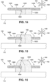
- printing may be paused or interrupted to allow the incorporation of elements such as first shaft 1300. However, in other embodiments, printing may be ongoing while first shaft 1300 is added to third partial structure 1200. In one embodiment, second actuating system 190 may be used to provide first shaft 1300 to third partial structure 1200.
- second recess 1202 may be selected to generally correspond at least in part to the size, shape, and dimensions of an element.
- second recess 1202 provides a recess surface 1304 that generally matches the contours of at least a portion of first shaft 1300.
- first shaft 1300 is moved in the direction of an arrow 1302, and is laid along recess surface 1304, at least a portion of first shaft 1300 can fit snugly and securely within the curvature provided by second recess 1202.
- second recess 1202 may be substantially larger than first shaft 1300 or otherwise provide a less secure fit to first shaft 1300.
- there may be no recess, or the curvature of second recess 1202 may be nearly flat such that first shaft 1300 rests on a surface that does not securely hold first shaft 1300.
- Fourth partial structure 1502 includes a second tunnel 1500, formed in part with the previously formed second recess 1202.
- second portion 1402 of first shaft 1300 is now covered by or enclosed within second tunnel 1500 of fourth partial structure 1502.
- FIG. 16 printing is completed, and a fourth structure 1600 has been formed.
- First shaft 1300 is positioned such that second portion 1402 of first shaft 1300 is disposed entirely within an interior portion of fourth structure 1600, while first portion 1400 and third portion 1404 are positioned outside of fourth structure 1600.
- first shaft 1300 may be removed or detached from fourth structure 1600.
- second actuating system 190 may be used to remove first shaft 1300 from fourth structure 1600.
- first shaft 1300 is pulled from second tunnel 1500 in direction of an arrow 1700.
- first shaft 1300 may be only partially removed from fourth structure 1600, or first shaft 1300 may be repositioned within fourth structure 1600.
- first portion 1400 is enclosed within fourth structure 1600, while second portion 1402 moves out of second tunnel 1500 and becomes exposed along with third portion 1404.
- first shaft 1300 may be removed from another direction, such that third portion 1404 becomes enclosed within fourth structure 1600, while second portion 1402 moves out of second tunnel 1500 and becomes exposed along with first portion 1400. In an alternative embodiment, first shaft 1300 may remain within second tunnel 1500. It should be noted that upon removal of first shaft 1300, first shaft 1300 may be reused.
- printing system 100 may allow formation of printed structures that include through-holes or other types of openings.
- the tunnels may be hollow or provide a space within the printed structure.
- printing system 100 may also be utilized to form blind-hole openings within a printed structure.
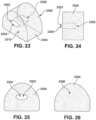
- FIGS. 23-26 various aspects of a sixth structure 2300 are depicted.
- FIG. 23 an isometric view of sixth structure 2300 is presented.
- a third tunnel 2302 of sixth structure 2300 can be seen to include a first end 2304 and a second end 2306 (represented by dotted lines). However, second end 2306 of third tunnel 2302 is disposed within the interior of sixth structure 2300.
- sixth structure 2300 includes a blind-hole aperture, so that there is an opening disposed along only a front side 2310 of sixth structure 2300.
- FIG. 24 a side-view of sixth structure 2300 is shown. The side view depicts the path of third tunnel 2302 through sixth structure 2300, from first end 2304 to second end 2306, represented by a dotted line.
- FIG. 25 is a front view and FIG. 26 is a rear view of sixth structure 2300. In FIG. 25 , the opening associated with first end 2304 of third tunnel 2302 can be seen along front side 2310. However, in FIG.
- third recess 2704 provides a recess surface 2708 that generally matches the contours of at least a portion of second shaft 2702.
- second shaft 2702 is moved in the direction of an arrow 2706, and is laid along recess surface 2708, at least a portion of second shaft 2702 can fit snugly and securely within the curvature provided by third recess 2704.
- third recess 2704 may be substantially larger than second shaft 2702 or otherwise provide a less secure fit to second shaft 2702.
- there may be no recess, or curvature of third recess 2704 may be nearly flat such that second shaft 2702 rests on a surface that does not include contours for securely holding second shaft 2702.
- second shaft 2702 has been placed along recess surface 2708 (see FIG. 27 ) of fifth partial structure 2700.
- additional layers have been printed over fifth partial structure 2700, as well as over second shaft 2702, forming a seventh structure 2900.
- Seventh structure 2900 includes a fourth tunnel 2902, formed in part with the previously formed third recess 2704.
- substantially the entire length and width of second shaft 2702 is now covered by or enclosed within fourth tunnel 2902 of seventh structure 2900.
- a composite printed structure 3000 can be formed, where an element (such as second shaft 2702) is joined, attached, enclosed, or otherwise disposed within the printed structure.
- a printed structure may be formed in some embodiments that is more resilient, rigid, and/or or includes the properties of both the printed material and the included element.
- composite printed structure 3000 includes fourth tunnel 2902 with a first end 3002 and a second end 3004. Second end 3004 is disposed within the interior of composite printed structure 3000.
- fourth tunnel 2902 forms a blind-hole aperture in composite printed structure 3000.
- an element such as second shaft 2702 may be placed or incorporated into composite printed structure 3000 such that both first end 3002 and second end 3004 are disposed in the interior of fourth tunnel 2902, and no opening is present on either a front side 3006 or a rear side 3008.
- a fully enclosed element located entirely within composite printed structure 3000 is possible in some embodiments, not according to the claims.
- printing system 100 may form composite printed structures with operative elements.
- Operative elements can include portions that are moveable relative to another portion of the operative element.
- an element may be disposed within a printed structure (e.g., second lace 700 in first tunnel 900 of third structure 1000, or first shaft 1300 in second tunnel 1500 of fourth structure 1600). While in some embodiments, an element may be removed (as shown in FIGS. 16-18 ), in other embodiments, the same element may be retained by the printed structure. In addition, in one embodiment, the element that is retained may be configured to move or slide through a tunnel formed in the printed structure.
- each of the elements described or mentioned herein may be configured such that they are disposed in a printed structure, but are not attached to any portion of the printed structure.
- an element may be disposed within a printed structure and also be able to readily move through and/or along the printed structure.
- second lace 700 in third structure 1000 may be moved in a generally horizontal direction 1002.
- second lace 700 may be able to slide or be moved translationally (back and forth) through first tunnel 900.
- This may provide the printed structure with the ability to act as a support, guide, router, covering, protection, sleeve, tube, anchor, or other such component for a portion of the element, while the element itself remains capable of movement through the printed structure.
- FIGS. 16-17 where first shaft 1300 is shown as it slides or moves through second tunnel 1500 of fourth structure 1600.
- first shaft 1300 is removed from fourth structure 1600.
- first shaft 1300 may remain within fourth structure 1300.
- first shaft 1300 can be configured to slide through second tunnel 1500 if so desired. It should also be understood that in some cases, an element may be removed from a printed structure, and a different element may be inserted within the same printed structure. Thus, although first shaft 1300 is removed from fourth structure 1300 in FIG. 18 , a lace or another shaft, or a different element altogether, may be placed, incorporated into or used with second tunnel 1500.
- Printing system 100 may provide for the translation of elements in the printed structures in a variety of ways.
- the materials comprising the printed structures may be different from the material comprising the elements.
- the materials of either or both of the printed material and elements may be resistant to adhesion.
- the use of dissimilar or incompatible materials that do not readily bind or adhere to one another, or, in one case, materials that repel binding, may be used in each of the printed structure and/or the element.
- the element may comprise a material that resists adhesion to the printed material.
- the element could comprise one or more materials that include lower friction coefficients, such as materials with friction coefficients in the range of 0.01 and 0.30.
- the printed material may comprise a material that resists adhesion to the element.
- the printed material could comprise a material with a lower friction coefficients, such as material with a friction coefficient in the range of 0.01 and 0.30
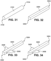
- FIGS. 31-34 present a few examples of elements that may be placed on, utilized, incorporated or otherwise joined to a printed structure.
- a cylindrical shaped third shaft 3100 is illustrated.
- Third shaft 3100 has a first end 3102 that is generally circular, and a second end 3104 that is also circular.
- third shaft 3100 is generally uniform along its length, and first end 3102 and second end 3104 are substantially similar.
- a rectangular cylinder type fourth shaft 3200 is depicted.
- Fourth shaft 3200 includes sharper edges at a first end 3202 and second end 3204 relative to third shaft 3100. Similar to third shaft 3100, fourth shaft 3200 is generally uniform along its length, and first end 3202 and second end 3204 are substantially similar.
- FIG. 33 illustrates a fifth shaft 3300 and FIG. 34 a sixth shaft 3400 that are substantially rectangular.
- fifth shaft 3300 includes a first vane 3306 and a second vane 3308 disposed along a first end 3302.
- sixth shaft 3400 includes a first vane 3406 and a second vane 3408 disposed along first end 3402.
- a vane is a bump, irregularity, or additional component or piece that is part of an element or disposed along the length of the element.
- the vanes are tapered, whereby the width of each vane decreases as it approaches first end 3302 of fifth shaft 3300 and first end 3402 of sixth shaft 3400 respectively.
- the tapering can provide a shaft with a smoother removal from a printed structure.
- Vanes and other additional features of elements may provide printed structures with different designs, and allow insertion of variously shaped components.
- vanes can enhance the aesthetic of a printed structure.
- vanes may help form sections in the tunnels that are necessary for the utilization of the printed structure.
- a second end 3304 of fifth shaft 3300 does not include a vane, nor does a second end 3404 of sixth shaft include a vane.
- fifth shaft 3300 and/or sixth shaft 3400 may include different types or numbers of vanes, as well as vanes of different sizes and shapes.
- fifth shaft 3300 in FIG. 33 has a first vane 3306 with a sharp edge
- sixth shaft in FIG. 34 has a first vane 3406 with a rounded edge relative to fifth shaft 3300.
- different types of shafts may be designed to provide a variety of different openings and tunnels or composites to a printed structure.
- third shaft 3100, fourth shaft 3200, fifth shaft 3300 and/or sixth shaft 3400 may be reusable.
- shape of an element, including any vanes, should allow it to be removed readily from the printed structure in which it was incorporated.
- the printed structures of the present embodiments may provide enhanced support.
- one or more printed structures may be attached to an underlying component such as a fabric layer of an upper or other article, and may act to enhance support over a portion of the component. This may occur in situations where the printed structure is more rigid than an underlying material (e.g., fabric, leather, etc.).
- FIGS. 35-38 depict an embodiment of an upper 3500 that includes an example of the printed structures described herein.
- Printed structures may be formed to provide eyelets or other lacing components in some embodiments.
- upper 3500 includes a plurality of partial structures 3502 that have been formed on print surface 148, which is a surface of upper 3500.
- Partial structures 3502 include a first partial structure 3504 and a second partial structure 3506 disposed along lateral side 206. Other partial structures 3502 are disposed along medial side 208.
- a plurality of lace elements 3600 have been introduced to upper 3500.
- Lace elements 3600 include a third lace 3602, a fourth lace 3604, a fifth lace 3606, and a sixth lace 3608.
- third lace 3602 and fourth lace 3604 are disposed along medial side 208
- fifth lace 3606 and sixth lace 3608 are disposed along lateral side 206.
- Lace elements 3600 have been disposed along upper 3500 such that each partial structure printed on upper 3500 is in contact with a lace element.
- first partial structure 3504 is in contact with sixth lace 3608, and second partial structure 3506 is in contact with fifth lace 3606.
- a lace end 3610 or another lace component may also be included with lace elements 3600. In other embodiments, there may be no additional components attached to lace elements 3600.
- Upper 3500 includes a plurality of structures 3700.
- Plurality of structures 3700 have incorporated plurality of lace elements 3600 within each structure.
- a seventh structure 3702 has incorporated a portion of sixth lace 3608 and an eighth structure 3704 has incorporated a portion of fifth lace 3606.
- structures 3700 may comprise a series of eyelets for lace elements 3600.
- structures 3700 may comprise any other component or part of upper 3500.
- FIG. 38 provides an illustration of an embodiment of flattened upper 3500 of FIGS. 35-37 that has been assembled as a three-dimensional upper 3802.
- Upper 3802, along with a sole structure 3804 and laces 3806, comprise a third article 3800.
- Third article 3800 is an article of footwear 3800 that includes printed structures 3700 with lace elements 3600. In different embodiments, a variety of designs, patterns, components, elements, structures, and other features may be included in an article using the techniques described herein.
- printed structures 3700 with lace elements 3600 can provide an aesthetic design for upper 3802 and/or and means for controlling tension across portions of upper 3802.
- printed structures 3700 may be arranged to control the positioning of lace elements 3600 so as to provide specific tensioning configurations.
- provisions may be included for adjusting the tension provided by lace elements, for example by including mechanisms for maintaining tension in one or more of the lace elements 3600.
Landscapes
- Engineering & Computer Science (AREA)
- Chemical & Material Sciences (AREA)
- Materials Engineering (AREA)
- Manufacturing & Machinery (AREA)
- Mechanical Engineering (AREA)
- Physics & Mathematics (AREA)
- Optics & Photonics (AREA)
- Epidemiology (AREA)
- Health & Medical Sciences (AREA)
- General Health & Medical Sciences (AREA)
- Public Health (AREA)
- Footwear And Its Accessory, Manufacturing Method And Apparatuses (AREA)
- Textile Engineering (AREA)
- Springs (AREA)
- Life Sciences & Earth Sciences (AREA)
- Biophysics (AREA)
- Professional, Industrial, Or Sporting Protective Garments (AREA)
- Lining And Supports For Tunnels (AREA)
- Braiding, Manufacturing Of Bobbin-Net Or Lace, And Manufacturing Of Nets By Knotting (AREA)
Claims (6)
- Article de vêtements (130) comportant :une première structure (220) formée d'un matériau imprimé (300) extrudé, déchargé, éjecté ou autrement émis via une buse (118), la première structure (220) comportant une première couche (400) et une seconde couche (402) ;un élément (194, 224), dans lequel l'élément (194, 224) est en contact avec la première structure (220) ; etune portion de l'élément (194, 224) étant partiellement enserrée au sein de la première structure (220),dans lequel l'élément (194, 224) est mobile au sein de la première structure (220) etdans lequel l'élément est un élément de laçage (132), un cordon, un fil, un cylindre, un tube, un arbre réutilisable (196) ou un arbre réutilisable (194, 224) qui inclut au moins une aube (3306, 3308, 3406, 3408).
- Article selon la revendication 1, dans lequel l'élément (194, 224) comporte un matériau qui résiste à l'adhérence au matériau imprimé de la première structure (220).
- Article selon l'une quelconque des revendications précédentes, dans lequel la première structure (220) comporte un évidement (602) et l'élément (194, 224) est reçu dans l'évidement (602).
- Article selon l'une quelconque des revendications précédentes, dans lequel l'élément (194, 224) est conçu pour être amovible par rapport à la première structure (220) pour former un premier tunnel (900).
- Article selon la revendication 4, dans lequel le premier tunnel (900) est un trou traversant ou un trou borgne.
- Article selon l'une quelconque des revendications précédentes, dans lequel le matériau imprimé inclut un matériau thermoplastique.
Applications Claiming Priority (8)
| Application Number | Priority Date | Filing Date | Title |
|---|---|---|---|
| US201562263834P | 2015-12-07 | 2015-12-07 | |
| US201562263923P | 2015-12-07 | 2015-12-07 | |
| US201562263916P | 2015-12-07 | 2015-12-07 | |
| US201562263891P | 2015-12-07 | 2015-12-07 | |
| US201562263898P | 2015-12-07 | 2015-12-07 | |
| PCT/US2016/065172 WO2017100197A1 (fr) | 2015-12-07 | 2016-12-06 | Impression en trois dimensions utilisant un élément captif |
| EP20206535.5A EP3795334B1 (fr) | 2015-12-07 | 2016-12-06 | Impression en trois dimensions utilisant un élément captif |
| EP16819773.9A EP3386730B1 (fr) | 2015-12-07 | 2016-12-06 | Impression en trois dimensions utilisant un élément captif |
Related Parent Applications (2)
| Application Number | Title | Priority Date | Filing Date |
|---|---|---|---|
| EP20206535.5A Division EP3795334B1 (fr) | 2015-12-07 | 2016-12-06 | Impression en trois dimensions utilisant un élément captif |
| EP16819773.9A Division EP3386730B1 (fr) | 2015-12-07 | 2016-12-06 | Impression en trois dimensions utilisant un élément captif |
Publications (2)
| Publication Number | Publication Date |
|---|---|
| EP4205589A1 EP4205589A1 (fr) | 2023-07-05 |
| EP4205589B1 true EP4205589B1 (fr) | 2025-01-22 |
Family
ID=57570658
Family Applications (10)
| Application Number | Title | Priority Date | Filing Date |
|---|---|---|---|
| EP23157550.7A Active EP4205589B1 (fr) | 2015-12-07 | 2016-12-06 | Impression tridimensionnelle utilisant un élément captif |
| EP16813333.8A Active EP3386330B1 (fr) | 2015-12-07 | 2016-12-06 | Article chaussant pourvu de structures tubulaires |
| EP16813334.6A Active EP3386331B1 (fr) | 2015-12-07 | 2016-12-06 | Article chaussant pourvu de structures tubulaires ayant des parties languettes |
| EP20186784.3A Active EP3744205B1 (fr) | 2015-12-07 | 2016-12-06 | Article chaussant pourvu de structures tubulaires |
| EP16820409.7A Active EP3386333B1 (fr) | 2015-12-07 | 2016-12-06 | Structures de ressort à tunnel |
| EP20206535.5A Active EP3795334B1 (fr) | 2015-12-07 | 2016-12-06 | Impression en trois dimensions utilisant un élément captif |
| EP16816556.1A Active EP3386332B1 (fr) | 2015-12-07 | 2016-12-06 | Tunnels segmentés sur des articles |
| EP16819773.9A Active EP3386730B1 (fr) | 2015-12-07 | 2016-12-06 | Impression en trois dimensions utilisant un élément captif |
| EP20188062.2A Active EP3750435B1 (fr) | 2015-12-07 | 2016-12-06 | Article chaussant pourvu de structures tubulaires ayant des parties languettes |
| EP21193163.9A Active EP3935986B1 (fr) | 2015-12-07 | 2016-12-06 | Tunnels segmentés sur des articles |
Family Applications After (9)
| Application Number | Title | Priority Date | Filing Date |
|---|---|---|---|
| EP16813333.8A Active EP3386330B1 (fr) | 2015-12-07 | 2016-12-06 | Article chaussant pourvu de structures tubulaires |
| EP16813334.6A Active EP3386331B1 (fr) | 2015-12-07 | 2016-12-06 | Article chaussant pourvu de structures tubulaires ayant des parties languettes |
| EP20186784.3A Active EP3744205B1 (fr) | 2015-12-07 | 2016-12-06 | Article chaussant pourvu de structures tubulaires |
| EP16820409.7A Active EP3386333B1 (fr) | 2015-12-07 | 2016-12-06 | Structures de ressort à tunnel |
| EP20206535.5A Active EP3795334B1 (fr) | 2015-12-07 | 2016-12-06 | Impression en trois dimensions utilisant un élément captif |
| EP16816556.1A Active EP3386332B1 (fr) | 2015-12-07 | 2016-12-06 | Tunnels segmentés sur des articles |
| EP16819773.9A Active EP3386730B1 (fr) | 2015-12-07 | 2016-12-06 | Impression en trois dimensions utilisant un élément captif |
| EP20188062.2A Active EP3750435B1 (fr) | 2015-12-07 | 2016-12-06 | Article chaussant pourvu de structures tubulaires ayant des parties languettes |
| EP21193163.9A Active EP3935986B1 (fr) | 2015-12-07 | 2016-12-06 | Tunnels segmentés sur des articles |
Country Status (4)
| Country | Link |
|---|---|
| US (12) | US11641909B2 (fr) |
| EP (10) | EP4205589B1 (fr) |
| CN (10) | CN113180333B (fr) |
| WO (5) | WO2017100204A1 (fr) |
Families Citing this family (42)
| Publication number | Priority date | Publication date | Assignee | Title |
|---|---|---|---|---|
| US10945488B2 (en) | 2013-08-09 | 2021-03-16 | Reebok International Limited | Article of footwear with extruded components |
| US9676159B2 (en) * | 2014-05-09 | 2017-06-13 | Nike, Inc. | Method for forming three-dimensional structures with different material portions |
| US9925440B2 (en) | 2014-05-13 | 2018-03-27 | Bauer Hockey, Llc | Sporting goods including microlattice structures |
| US9756899B2 (en) * | 2015-02-20 | 2017-09-12 | Nike, Inc. | Article of footwear having an upper with connectors for attaching to a sole structure |
| WO2017100204A1 (fr) * | 2015-12-07 | 2017-06-15 | Nike Innovate C.V. | Article chaussant pourvu de structures tubulaires |
| EP3257985A1 (fr) | 2016-06-06 | 2017-12-20 | Fuerst Group, Inc. | Système et procédé de production automatique d'une structure en cordon |
| EP3585620B1 (fr) | 2017-02-27 | 2024-05-15 | Kornit Digital Technologies Ltd. | Dispositifs d'impression 3d comprenant des buses de mélange |
| US11904614B2 (en) | 2017-02-27 | 2024-02-20 | Kornit Digital Technologies Ltd. | Multi-input print heads for three-dimensionally printing and associated systems and methods |
| US11701813B2 (en) * | 2017-02-27 | 2023-07-18 | Kornit Digital Technologies Ltd. | Methods for three-dimensionally printing and associated multi-input print heads and systems |
| EP3644779B1 (fr) | 2017-06-27 | 2020-08-12 | Puma Se | Chaussure, en particulier chaussure de sport |
| US10485302B2 (en) * | 2017-07-07 | 2019-11-26 | Reebok International Limited | Method of making an upper |
| US20190015923A1 (en) * | 2017-07-11 | 2019-01-17 | United Technologies Corporation | Additively manufactured article including electrically removable supports |
| US10711380B2 (en) | 2017-07-13 | 2020-07-14 | Under Armour, Inc. | Article with embroidered tape segments |
| TWI751023B (zh) * | 2017-10-24 | 2021-12-21 | 荷蘭商耐克創新有限合夥公司 | 製造多種產品的方法 |
| US11795595B2 (en) | 2017-10-24 | 2023-10-24 | Nike, Inc. | Manufacturing frame |
| US10583605B2 (en) * | 2018-04-19 | 2020-03-10 | The Boeing Company | Drop draw/extrude (DD/E) printing method |
| EP3802077B1 (fr) * | 2018-06-04 | 2025-08-06 | Conseil et Technique | Procede de fabrication d'une piece en materiau composite |
| US10786043B2 (en) | 2018-07-03 | 2020-09-29 | Under Armour, Inc. | Article with thermally bonded ribbon structure and method of making |
| US10736380B2 (en) | 2018-07-03 | 2020-08-11 | Under Armour, Inc. | Article with ribbon structure and embroidered edges |
| US10758007B2 (en) | 2018-07-03 | 2020-09-01 | Under Armour, Inc. | Article with thermally bonded ribbon structure and method of making |
| US10619280B2 (en) | 2018-07-03 | 2020-04-14 | Under Armour, Inc. | Method of making article with ribbon structure and embroidered edges |
| US10736381B2 (en) | 2018-07-03 | 2020-08-11 | Under Armour, Inc. | Article with directional tensioning |
| US10716362B2 (en) | 2018-07-03 | 2020-07-21 | Under Armour, Inc. | Article with ribbon structure having nodes and links |
| CN116369621A (zh) * | 2018-08-31 | 2023-07-04 | 耐克创新有限合伙公司 | 具有带凹口的线轴的自动系带鞋类马达 |
| CN115708608B (zh) * | 2018-09-19 | 2026-02-13 | 耐克创新有限合伙公司 | 区域动态系带系统 |
| US10993497B2 (en) * | 2018-11-15 | 2021-05-04 | Under Armour, Inc. | Article with ribbon loops for string lasting |
| CN110171201A (zh) * | 2019-05-08 | 2019-08-27 | 珠海许继电气有限公司 | 一种uv彩印制作功能指示面板的方法及装置 |
| CA3140503C (fr) | 2019-05-21 | 2022-06-14 | Bauer Hockey Ltd. | Casques comprenant des composants fabriques de maniere additive |
| CN112515291B (zh) * | 2019-09-19 | 2025-07-04 | 苏州星诺奇科技股份有限公司 | 可穿戴制品 |
| IT201900025051A1 (it) * | 2019-12-20 | 2021-06-20 | Geox Spa | Dispositivo luminoso e struttura di suola comprendente detto dispositivo luminoso |
| CN111319366A (zh) * | 2020-04-02 | 2020-06-23 | 深圳诚拓数码设备有限公司 | 一种印花装置以及印花系统 |
| CA3185177A1 (fr) * | 2020-07-07 | 2022-01-13 | Simonne C. Cormier | Dispositif prothetique mammaire, systeme de fixation et utilisations associees |
| EP4188676A1 (fr) * | 2020-07-27 | 2023-06-07 | Stratasys Ltd. | Procédé et système permettant de réaliser une impression en 3d sur un tissu |
| IT202000021952A1 (it) * | 2020-09-17 | 2022-03-17 | Terzopiano S R L | Metodo di stampa 3d diretta su tessuto e relativo tessuto con porzione stampa 3d |
| EP4259436A4 (fr) * | 2020-12-14 | 2024-10-09 | NTT Research, Inc. | Dispositifs imprimés en 3d et procédé d'utilisation |
| CN116615122A (zh) * | 2020-12-23 | 2023-08-18 | 株式会社爱世克私 | 鞋面及具备该鞋面的鞋子 |
| CN112754108B (zh) * | 2021-01-12 | 2022-02-18 | 浙江纺织服装职业技术学院 | 一种鞋带自动穿引导装置 |
| CA3113195A1 (fr) * | 2021-03-24 | 2022-09-24 | David Lundquist | Appareil de verrouillage de lacet |
| US12228188B2 (en) * | 2021-05-13 | 2025-02-18 | Moffitt, LLC | Methods and apparatus for a 3D-printed spring |
| US12588738B2 (en) | 2022-12-15 | 2026-03-31 | Nike, Inc. | Recyclable footwear article |
| JP2024148754A (ja) * | 2023-04-06 | 2024-10-18 | 株式会社アシックス | シューズ |
| CN117380957A (zh) * | 2023-10-27 | 2024-01-12 | 成都先进金属材料产业技术研究院股份有限公司 | 一种3d打印钛合金弹簧总成及其制备方法和应用 |
Citations (1)
| Publication number | Priority date | Publication date | Assignee | Title |
|---|---|---|---|---|
| US20130071599A1 (en) * | 2011-08-04 | 2013-03-21 | Arburg Gmbh + Co. Kg | Method for producing a three-dimensional object from solidifiable material as well as an object produced therewith |
Family Cites Families (110)
| Publication number | Priority date | Publication date | Assignee | Title |
|---|---|---|---|---|
| GB601440A (en) | 1946-05-24 | 1948-05-05 | William Lennart Grut | Improvements in or relating to toys and the like |
| US1862047A (en) * | 1930-07-08 | 1932-06-07 | Robert L Boulet | Shoe fastening device |
| US2112613A (en) * | 1936-04-04 | 1938-03-29 | Sol J Waxelbaum | Shoe |
| US2143556A (en) * | 1937-11-17 | 1939-01-10 | Hodaly Emerick | Soft shoe |
| US4870761A (en) * | 1988-03-09 | 1989-10-03 | Tracy Richard J | Shoe construction and closure components thereof |
| CZ288491B6 (en) * | 1989-06-03 | 2001-06-13 | Dassler Puma Sportschuh | Shoe with flexible upper material provided with a closing device |
| US5121329A (en) | 1989-10-30 | 1992-06-09 | Stratasys, Inc. | Apparatus and method for creating three-dimensional objects |
| IT225832Y1 (it) * | 1991-06-10 | 1997-01-24 | Arkos Srl | Dispositivo di bloccaggio del piede particolarmente per calzature da t rekking |
| US5203944A (en) | 1991-10-10 | 1993-04-20 | Prinz Fritz B | Method for fabrication of three-dimensional articles by thermal spray deposition using masks as support structures |
| FR2692115B1 (fr) | 1992-06-10 | 1995-06-23 | Mainguene Patrick | Chaussure munie d'un dispositif de tenue de pied. |
| US5510066A (en) | 1992-08-14 | 1996-04-23 | Guild Associates, Inc. | Method for free-formation of a free-standing, three-dimensional body |
| US5362427A (en) | 1993-05-10 | 1994-11-08 | Mitchell Jr Porter H | Method and apparatus for manufacturing an article using a support structure for supporting an article during manufacture therefor |
| DE9307480U1 (de) | 1993-05-28 | 1994-10-06 | Puma Ag Rudolf Dassler Sport, 91074 Herzogenaurach | Schuh mit einem Zentraldrehverschluß |
| US5371957A (en) * | 1993-12-14 | 1994-12-13 | Adidas America, Inc. | Athletic shoe |
| EP0746214B1 (fr) * | 1994-02-28 | 1999-12-08 | Adam H. Oreck | Chaussure avec lacets passant dans des tubes |
| US5535531A (en) | 1994-04-28 | 1996-07-16 | Karabed; Razmik | Shoelace rapid tightening apparatus |
| US5755044A (en) * | 1996-01-04 | 1998-05-26 | Veylupek; Robert J. | Shoe lacing system |
| US5682654A (en) | 1996-04-18 | 1997-11-04 | Fila U.S.A., Inc. | Closure element |
| US6082867A (en) | 1996-11-29 | 2000-07-04 | Chien; Tseng-Lu | Lighting arrangements including a three-dimensional electro-luminscent element |
| FR2757026B1 (fr) * | 1996-12-17 | 1999-02-26 | Salomon Sa | Ensemble bloqueur |
| USD390695S (en) * | 1997-05-08 | 1998-02-17 | Fila U.S.A., Inc. | Shoe lace elements |
| US20060156517A1 (en) * | 1997-08-22 | 2006-07-20 | Hammerslag Gary R | Reel based closure system |
| US6032387A (en) | 1998-03-26 | 2000-03-07 | Johnson; Gregory G. | Automated tightening and loosening shoe |
| US6088936A (en) * | 1999-01-28 | 2000-07-18 | Bahl; Loveleen | Shoe with closure system |
| US6286233B1 (en) * | 1999-04-08 | 2001-09-11 | David E Gaither | Internally laced shoe |
| US7219449B1 (en) * | 1999-05-03 | 2007-05-22 | Promdx Technology, Inc. | Adaptively controlled footwear |
| DE10208853C1 (de) | 2002-03-01 | 2003-06-26 | Goodwell Int Ltd | Schnürschuh |
| AU2003900180A0 (en) * | 2003-01-16 | 2003-01-30 | Silverbrook Research Pty Ltd | Method and apparatus (dam001) |
| US20040181972A1 (en) * | 2003-03-19 | 2004-09-23 | Julius Csorba | Mechanism of tying of shoes circumferentially embracing the foot within the shoe |
| US8123350B2 (en) | 2003-06-03 | 2012-02-28 | Hexagon Metrology Ab | Computerized apparatus and method for applying graphics to surfaces |
| US6922917B2 (en) | 2003-07-30 | 2005-08-02 | Dashamerica, Inc. | Shoe tightening system |
| US7370440B1 (en) * | 2003-08-08 | 2008-05-13 | Cole Iii Charles D | Footwear cinch |
| TWM243060U (en) * | 2003-08-29 | 2004-09-11 | Champion Biotechnology Co Ltd | Dynamic foot arch stabilizing protection pad |
| SE0303242D0 (sv) * | 2003-12-02 | 2003-12-02 | Sca Hygiene Prod Ab | Disposable absorbent article having tension indicators |
| CN2699699Y (zh) * | 2004-04-30 | 2005-05-18 | 天津成湖实业有限公司 | 一种可调节的鞋 |
| FR2872389A1 (fr) | 2004-07-02 | 2006-01-06 | Salomon Sa | Article chaussant et systeme de lacage pour un tel article |
| US8192828B2 (en) | 2004-12-06 | 2012-06-05 | Nike, Inc. | Material formed of multiple links and method of forming same |
| US8065818B2 (en) * | 2005-06-20 | 2011-11-29 | Nike, Inc. | Article of footwear having an upper with a matrix layer |
| US7540097B2 (en) * | 2005-06-20 | 2009-06-02 | Nike, Inc. | Article of footwear having an upper with a matrix layer |
| US7721468B1 (en) * | 2005-08-26 | 2010-05-25 | Gregory G. Johnson | Tightening shoe |
| FR2891118B1 (fr) * | 2005-09-28 | 2007-12-21 | Salomon Sa | Chaussure qui ameliore le serrage de la tige |
| US8020319B1 (en) * | 2005-11-29 | 2011-09-20 | Anne Elizabeth Mohaupt | Shoe with elastic bindings to receive interchangeable straps |
| US20070186447A1 (en) | 2006-02-10 | 2007-08-16 | Arturo Ramos | Inner Lacing Shoes |
| US7540100B2 (en) * | 2006-05-18 | 2009-06-02 | The Timberland Company | Footwear article with adjustable stiffness |
| ITFI20060043U1 (it) * | 2006-07-12 | 2008-01-13 | David Paolo Spinelli | Calzatura con suola e tomaia separabili |
| DE102007002367A1 (de) * | 2007-01-17 | 2008-07-24 | Deeluxe Sportartikel Handels Gmbh | Stiefel, insbesondere Ski- oder Snowboardstiefel |
| GB0710404D0 (en) * | 2007-05-31 | 2007-07-11 | Ussher Timothy J | Powered shoe tightening with lace cord guiding system |
| US8117770B2 (en) | 2007-06-29 | 2012-02-21 | Wong Darrell L | Footwear device |
| DE102007040147B4 (de) * | 2007-08-24 | 2009-07-09 | Powerslide Sportartikelvertriebs Gmbh | Sportschuh |
| GB2452511A (en) * | 2007-09-05 | 2009-03-11 | Benjamin Holmes Peter Shine | Lace and loop assembly system |
| US8037621B2 (en) * | 2007-09-13 | 2011-10-18 | Nike, Inc. | Article of footwear including a woven strap system |
| US8037547B2 (en) * | 2007-12-12 | 2011-10-18 | Scott Technologies, Inc. | Protective hood |
| US8245418B2 (en) | 2008-03-01 | 2012-08-21 | Paintin Janet A | Front-opening footwear systems |
| US20100021638A1 (en) | 2008-07-28 | 2010-01-28 | Solidscape, Inc. | Method for fabricating three dimensional models |
| US8051585B2 (en) * | 2008-11-06 | 2011-11-08 | Nike, Inc. | Article of footwear comprising a plurality of strips |
| AU2010262807B2 (en) * | 2009-06-19 | 2014-02-20 | Specialized Bicycle Components, Inc. | Cycling shoe with rear entry |
| JP5768064B2 (ja) * | 2010-01-21 | 2015-08-26 | ボア テクノロジー, インク. | 紐締めシステム及び紐締めシステムを締め付ける方法 |
| US20110308108A1 (en) | 2010-06-21 | 2011-12-22 | Under Armour, Inc. | Foot support article |
| TWI457088B (zh) | 2010-10-26 | 2014-10-21 | Taiwan Paiho Ltd | Velcro with hair surface manufacturing methods, manufacturing equipment and velcro hair surface |
| US8931146B2 (en) * | 2010-12-10 | 2015-01-13 | Converse Inc. | Multiple material tying lace |
| US8756833B2 (en) | 2011-01-06 | 2014-06-24 | Nike, Inc. | Lacing closure system for an object |
| US8657773B2 (en) * | 2011-05-27 | 2014-02-25 | Doak Ostergard | Ankle brace |
| US8865047B2 (en) | 2011-05-31 | 2014-10-21 | Stratasys Ltd. | Solid freeform fabrication of easily removeable support constructions |
| JP2013006269A (ja) | 2011-06-23 | 2013-01-10 | Raytheon Bbn Technologies Corp | ロボット加工装置 |
| US8844167B2 (en) * | 2011-07-18 | 2014-09-30 | Nike, Inc. | Article of footwear having an upper with cord elements |
| US8898931B2 (en) * | 2011-07-22 | 2014-12-02 | Nike, Inc. | Folded loop fastening system for an article of footwear |
| US8904673B2 (en) * | 2011-08-18 | 2014-12-09 | Palidium, Inc. | Automated tightening shoe |
| US8844168B2 (en) * | 2011-10-06 | 2014-09-30 | Nike, Inc. | Footwear lacing system |
| US8755925B2 (en) * | 2011-11-18 | 2014-06-17 | Nike, Inc. | Automated identification and assembly of shoe parts |
| US9078490B2 (en) | 2011-11-29 | 2015-07-14 | Nike, Inc. | Ankle and foot support system |
| EP2809191B1 (fr) * | 2012-02-04 | 2018-09-26 | Puma Se | Chaussure, en particulier chaussure de sport |
| US8819963B2 (en) * | 2012-02-24 | 2014-09-02 | Nike, Inc. | Articles of footwear with tensile strand elements |
| US9737117B2 (en) * | 2012-03-16 | 2017-08-22 | Asics Corporation | Lace fitting structure |
| US9019359B2 (en) | 2012-03-29 | 2015-04-28 | Nike, Inc. | Foot imaging and measurement apparatus |
| US20150099087A1 (en) * | 2012-04-10 | 2015-04-09 | A. Raymond Et Cie | Printed encapsulation |
| US20130298426A1 (en) * | 2012-05-14 | 2013-11-14 | Elisha George Pierce | Tongueless Footwear With A Canopy |
| US9005710B2 (en) | 2012-07-19 | 2015-04-14 | Nike, Inc. | Footwear assembly method with 3D printing |
| US8993061B2 (en) * | 2012-07-19 | 2015-03-31 | Nike, Inc. | Direct printing to fabric |
| US9977840B2 (en) | 2012-08-29 | 2018-05-22 | Prem Makeig | Computer-implemented methods for generating 3D models suitable for 3D printing |
| US20140130375A1 (en) | 2012-11-15 | 2014-05-15 | Nike, Inc. | Article Of Footwear Incorporating A Knitted Component |
| US9861160B2 (en) * | 2012-11-30 | 2018-01-09 | Nike, Inc. | Article of footwear incorporating a knitted component |
| US9474324B2 (en) * | 2012-12-07 | 2016-10-25 | Nike, Inc. | Article of footwear with adjustable stiffness |
| US9226548B2 (en) * | 2013-01-15 | 2016-01-05 | Nike, Inc. | Spacer textile material with channels having multiple tensile strands |
| US9095186B2 (en) | 2013-01-15 | 2015-08-04 | Nike, Inc. | Article of footwear incorporating braided tensile strands |
| US9241537B2 (en) | 2013-01-15 | 2016-01-26 | Nike, Inc. | Spacer textile material with tensile strands that intersect |
| US9144263B2 (en) | 2013-02-14 | 2015-09-29 | Nike, Inc. | Article of footwear with interconnected tensile strands |
| US9480299B2 (en) | 2013-03-14 | 2016-11-01 | Red Wing Shoe Company, Inc. | Slip-on footwear with foot securing system |
| US9060567B2 (en) * | 2013-03-22 | 2015-06-23 | Nike, Inc. | Article of footwear with tensile structure |
| AU2014302635B8 (en) * | 2013-06-24 | 2018-12-06 | President And Fellows Of Harvard College | Printed three-dimensional (3D) functional part and method of making |
| CN104337123A (zh) * | 2013-07-25 | 2015-02-11 | 翁中飞 | 一种系带系统 |
| US8701232B1 (en) * | 2013-09-05 | 2014-04-22 | Nike, Inc. | Method of forming an article of footwear incorporating a trimmed knitted upper |
| WO2015035257A2 (fr) * | 2013-09-05 | 2015-03-12 | Boa Technology Inc. | Variantes de guides de laçage pour serrer des mécanismes et procédés associés |
| PL3957459T3 (pl) * | 2013-09-27 | 2025-11-03 | Tactotek Oy | Sposób wytwarzania struktury elektromechanicznej i układ do realizacji tego sposobu |
| US9072335B1 (en) * | 2014-02-03 | 2015-07-07 | Nike, Inc. | Knitted component for an article of footwear including a full monofilament upper |
| US8973410B1 (en) * | 2014-02-03 | 2015-03-10 | Nike, Inc. | Method of knitting a gusseted tongue for a knitted component |
| US20150237962A1 (en) | 2014-02-24 | 2015-08-27 | Boa Technology, Inc. | Closure devices and methods for golf shoes |
| US9861162B2 (en) * | 2014-04-08 | 2018-01-09 | Nike, Inc. | Components for articles of footwear including lightweight, selectively supported textile components |
| US9629418B2 (en) * | 2014-04-15 | 2017-04-25 | Nike, Inc. | Footwear having motorized adjustment system and elastic upper |
| US9676159B2 (en) * | 2014-05-09 | 2017-06-13 | Nike, Inc. | Method for forming three-dimensional structures with different material portions |
| US9301567B2 (en) * | 2014-08-29 | 2016-04-05 | Nike, Inc. | Article of footwear incorporating a knitted component with monofilament areas |
| US9192204B1 (en) * | 2014-09-30 | 2015-11-24 | Nike, Inc. | Article of footwear upper incorporating a textile component with tensile elements |
| US9078488B1 (en) * | 2014-09-30 | 2015-07-14 | Nike, Inc. | Article of footwear incorporating a lenticular knit structure |
| EP3636096B1 (fr) * | 2014-11-12 | 2021-07-28 | NIKE Innovate C.V. | Procédé de fabrication d'un ensemble semelle pour chaussure |
| US10226103B2 (en) * | 2015-01-05 | 2019-03-12 | Markforged, Inc. | Footwear fabrication by composite filament 3D printing |
| US9788599B2 (en) * | 2015-06-03 | 2017-10-17 | Taylor Made Golf Company, Inc. | Torsion control bridge for shoe |
| CN204763616U (zh) * | 2015-07-16 | 2015-11-18 | 台湾百和工业股份有限公司 | 立体布面拉环结构及具有立体布面拉环结构的随身产品 |
| US9706812B2 (en) * | 2015-09-03 | 2017-07-18 | Saucony, Inc. | Footwear lacing system and related methods |
| WO2017100204A1 (fr) * | 2015-12-07 | 2017-06-15 | Nike Innovate C.V. | Article chaussant pourvu de structures tubulaires |
| CN106974354B (zh) * | 2016-01-19 | 2021-02-09 | 富尔斯特集团有限公司 | 具有绳结构的鞋品 |
| CA3135709A1 (fr) * | 2018-03-30 | 2019-10-03 | Pandere Shoes, Inc. | Chaussure reglable |
-
2016
- 2016-12-06 WO PCT/US2016/065184 patent/WO2017100204A1/fr not_active Ceased
- 2016-12-06 CN CN202110523796.9A patent/CN113180333B/zh active Active
- 2016-12-06 US US15/370,934 patent/US11641909B2/en active Active
- 2016-12-06 EP EP23157550.7A patent/EP4205589B1/fr active Active
- 2016-12-06 EP EP16813333.8A patent/EP3386330B1/fr active Active
- 2016-12-06 CN CN201680071714.9A patent/CN108366641B/zh active Active
- 2016-12-06 CN CN202110063296.1A patent/CN112890373B/zh active Active
- 2016-12-06 EP EP16813334.6A patent/EP3386331B1/fr active Active
- 2016-12-06 US US15/370,913 patent/US10065369B2/en active Active
- 2016-12-06 US US15/370,976 patent/US10492566B2/en active Active
- 2016-12-06 CN CN202111446617.2A patent/CN114145535B/zh active Active
- 2016-12-06 EP EP20186784.3A patent/EP3744205B1/fr active Active
- 2016-12-06 WO PCT/US2016/065187 patent/WO2017100207A2/fr not_active Ceased
- 2016-12-06 US US15/370,957 patent/US10702019B2/en active Active
- 2016-12-06 EP EP16820409.7A patent/EP3386333B1/fr active Active
- 2016-12-06 CN CN201680071212.6A patent/CN108289525B/zh active Active
- 2016-12-06 EP EP20206535.5A patent/EP3795334B1/fr active Active
- 2016-12-06 WO PCT/US2016/065185 patent/WO2017100205A1/fr not_active Ceased
- 2016-12-06 WO PCT/US2016/065172 patent/WO2017100197A1/fr not_active Ceased
- 2016-12-06 EP EP16816556.1A patent/EP3386332B1/fr active Active
- 2016-12-06 CN CN201680071845.7A patent/CN108366643B/zh active Active
- 2016-12-06 CN CN201680071839.1A patent/CN108366642B/zh active Active
- 2016-12-06 CN CN202110366576.XA patent/CN113080569A/zh active Pending
- 2016-12-06 EP EP16819773.9A patent/EP3386730B1/fr active Active
- 2016-12-06 CN CN201680071448.XA patent/CN108367496B/zh active Active
- 2016-12-06 EP EP20188062.2A patent/EP3750435B1/fr active Active
- 2016-12-06 CN CN202011277183.3A patent/CN112385933B/zh active Active
- 2016-12-06 WO PCT/US2016/065181 patent/WO2017100202A2/fr not_active Ceased
- 2016-12-06 EP EP21193163.9A patent/EP3935986B1/fr active Active
- 2016-12-06 US US15/370,893 patent/US10144173B2/en active Active
-
2018
- 2018-05-10 US US15/976,714 patent/US10813410B2/en active Active
- 2018-07-05 US US16/028,306 patent/US10517354B2/en active Active
-
2019
- 2019-11-11 US US16/680,306 patent/US11666120B2/en active Active
- 2019-12-13 US US16/714,624 patent/US11033077B2/en active Active
-
2020
- 2020-06-29 US US16/915,403 patent/US10912351B2/en active Active
-
2021
- 2021-01-26 US US17/158,995 patent/US20210145125A1/en active Pending
-
2023
- 2023-04-25 US US18/306,940 patent/US12369691B2/en active Active
Patent Citations (1)
| Publication number | Priority date | Publication date | Assignee | Title |
|---|---|---|---|---|
| US20130071599A1 (en) * | 2011-08-04 | 2013-03-21 | Arburg Gmbh + Co. Kg | Method for producing a three-dimensional object from solidifiable material as well as an object produced therewith |
Also Published As
Similar Documents
| Publication | Publication Date | Title |
|---|---|---|
| US10912351B2 (en) | Three-dimensional printing utilizing a captive element | |
| US12317962B2 (en) | Three-dimensional printing of a traced element | |
| US12478129B2 (en) | Three-dimensional printing along a curved surface |
Legal Events
| Date | Code | Title | Description |
|---|---|---|---|
| PUAI | Public reference made under article 153(3) epc to a published international application that has entered the european phase |
Free format text: ORIGINAL CODE: 0009012 |
|
| STAA | Information on the status of an ep patent application or granted ep patent |
Free format text: STATUS: THE APPLICATION HAS BEEN PUBLISHED |
|
| AC | Divisional application: reference to earlier application |
Ref document number: 3386730 Country of ref document: EP Kind code of ref document: P Ref document number: 3795334 Country of ref document: EP Kind code of ref document: P |
|
| AK | Designated contracting states |
Kind code of ref document: A1 Designated state(s): AL AT BE BG CH CY CZ DE DK EE ES FI FR GB GR HR HU IE IS IT LI LT LU LV MC MK MT NL NO PL PT RO RS SE SI SK SM TR |
|
| STAA | Information on the status of an ep patent application or granted ep patent |
Free format text: STATUS: REQUEST FOR EXAMINATION WAS MADE |
|
| 17P | Request for examination filed |
Effective date: 20231214 |
|
| RBV | Designated contracting states (corrected) |
Designated state(s): AL AT BE BG CH CY CZ DE DK EE ES FI FR GB GR HR HU IE IS IT LI LT LU LV MC MK MT NL NO PL PT RO RS SE SI SK SM TR |
|
| STAA | Information on the status of an ep patent application or granted ep patent |
Free format text: STATUS: EXAMINATION IS IN PROGRESS |
|
| 17Q | First examination report despatched |
Effective date: 20240124 |
|
| P01 | Opt-out of the competence of the unified patent court (upc) registered |
Effective date: 20240522 |
|
| GRAP | Despatch of communication of intention to grant a patent |
Free format text: ORIGINAL CODE: EPIDOSNIGR1 |
|
| STAA | Information on the status of an ep patent application or granted ep patent |
Free format text: STATUS: GRANT OF PATENT IS INTENDED |
|
| INTG | Intention to grant announced |
Effective date: 20240812 |
|
| GRAS | Grant fee paid |
Free format text: ORIGINAL CODE: EPIDOSNIGR3 |
|
| GRAA | (expected) grant |
Free format text: ORIGINAL CODE: 0009210 |
|
| STAA | Information on the status of an ep patent application or granted ep patent |
Free format text: STATUS: THE PATENT HAS BEEN GRANTED |
|
| AC | Divisional application: reference to earlier application |
Ref document number: 3386730 Country of ref document: EP Kind code of ref document: P Ref document number: 3795334 Country of ref document: EP Kind code of ref document: P |
|
| AK | Designated contracting states |
Kind code of ref document: B1 Designated state(s): AL AT BE BG CH CY CZ DE DK EE ES FI FR GB GR HR HU IE IS IT LI LT LU LV MC MK MT NL NO PL PT RO RS SE SI SK SM TR |
|
| REG | Reference to a national code |
Ref country code: GB Ref legal event code: FG4D |
|
| REG | Reference to a national code |
Ref country code: CH Ref legal event code: EP |
|
| REG | Reference to a national code |
Ref country code: IE Ref legal event code: FG4D |
|
| REG | Reference to a national code |
Ref country code: DE Ref legal event code: R096 Ref document number: 602016091068 Country of ref document: DE |
|
| REG | Reference to a national code |
Ref country code: NL Ref legal event code: MP Effective date: 20250122 |
|
| PG25 | Lapsed in a contracting state [announced via postgrant information from national office to epo] |
Ref country code: NL Free format text: LAPSE BECAUSE OF FAILURE TO SUBMIT A TRANSLATION OF THE DESCRIPTION OR TO PAY THE FEE WITHIN THE PRESCRIBED TIME-LIMIT Effective date: 20250122 |
|
| PG25 | Lapsed in a contracting state [announced via postgrant information from national office to epo] |
Ref country code: RS Free format text: LAPSE BECAUSE OF FAILURE TO SUBMIT A TRANSLATION OF THE DESCRIPTION OR TO PAY THE FEE WITHIN THE PRESCRIBED TIME-LIMIT Effective date: 20250422 |
|
| PG25 | Lapsed in a contracting state [announced via postgrant information from national office to epo] |
Ref country code: FI Free format text: LAPSE BECAUSE OF FAILURE TO SUBMIT A TRANSLATION OF THE DESCRIPTION OR TO PAY THE FEE WITHIN THE PRESCRIBED TIME-LIMIT Effective date: 20250122 |
|
| PG25 | Lapsed in a contracting state [announced via postgrant information from national office to epo] |
Ref country code: PL Free format text: LAPSE BECAUSE OF FAILURE TO SUBMIT A TRANSLATION OF THE DESCRIPTION OR TO PAY THE FEE WITHIN THE PRESCRIBED TIME-LIMIT Effective date: 20250122 |
|
| PG25 | Lapsed in a contracting state [announced via postgrant information from national office to epo] |
Ref country code: ES Free format text: LAPSE BECAUSE OF FAILURE TO SUBMIT A TRANSLATION OF THE DESCRIPTION OR TO PAY THE FEE WITHIN THE PRESCRIBED TIME-LIMIT Effective date: 20250122 |
|
| REG | Reference to a national code |
Ref country code: LT Ref legal event code: MG9D |
|
| PG25 | Lapsed in a contracting state [announced via postgrant information from national office to epo] |
Ref country code: NO Free format text: LAPSE BECAUSE OF FAILURE TO SUBMIT A TRANSLATION OF THE DESCRIPTION OR TO PAY THE FEE WITHIN THE PRESCRIBED TIME-LIMIT Effective date: 20250422 Ref country code: IS Free format text: LAPSE BECAUSE OF FAILURE TO SUBMIT A TRANSLATION OF THE DESCRIPTION OR TO PAY THE FEE WITHIN THE PRESCRIBED TIME-LIMIT Effective date: 20250522 |
|
| REG | Reference to a national code |
Ref country code: AT Ref legal event code: MK05 Ref document number: 1760748 Country of ref document: AT Kind code of ref document: T Effective date: 20250122 |
|
| PG25 | Lapsed in a contracting state [announced via postgrant information from national office to epo] |
Ref country code: HR Free format text: LAPSE BECAUSE OF FAILURE TO SUBMIT A TRANSLATION OF THE DESCRIPTION OR TO PAY THE FEE WITHIN THE PRESCRIBED TIME-LIMIT Effective date: 20250122 |
|
| PG25 | Lapsed in a contracting state [announced via postgrant information from national office to epo] |
Ref country code: PT Free format text: LAPSE BECAUSE OF FAILURE TO SUBMIT A TRANSLATION OF THE DESCRIPTION OR TO PAY THE FEE WITHIN THE PRESCRIBED TIME-LIMIT Effective date: 20250522 Ref country code: LV Free format text: LAPSE BECAUSE OF FAILURE TO SUBMIT A TRANSLATION OF THE DESCRIPTION OR TO PAY THE FEE WITHIN THE PRESCRIBED TIME-LIMIT Effective date: 20250122 |
|
| PG25 | Lapsed in a contracting state [announced via postgrant information from national office to epo] |
Ref country code: BG Free format text: LAPSE BECAUSE OF FAILURE TO SUBMIT A TRANSLATION OF THE DESCRIPTION OR TO PAY THE FEE WITHIN THE PRESCRIBED TIME-LIMIT Effective date: 20250122 Ref country code: GR Free format text: LAPSE BECAUSE OF FAILURE TO SUBMIT A TRANSLATION OF THE DESCRIPTION OR TO PAY THE FEE WITHIN THE PRESCRIBED TIME-LIMIT Effective date: 20250423 |
|
| PG25 | Lapsed in a contracting state [announced via postgrant information from national office to epo] |
Ref country code: AT Free format text: LAPSE BECAUSE OF FAILURE TO SUBMIT A TRANSLATION OF THE DESCRIPTION OR TO PAY THE FEE WITHIN THE PRESCRIBED TIME-LIMIT Effective date: 20250122 |
|
| PG25 | Lapsed in a contracting state [announced via postgrant information from national office to epo] |
Ref country code: SE Free format text: LAPSE BECAUSE OF FAILURE TO SUBMIT A TRANSLATION OF THE DESCRIPTION OR TO PAY THE FEE WITHIN THE PRESCRIBED TIME-LIMIT Effective date: 20250122 |
|
| PG25 | Lapsed in a contracting state [announced via postgrant information from national office to epo] |
Ref country code: SM Free format text: LAPSE BECAUSE OF FAILURE TO SUBMIT A TRANSLATION OF THE DESCRIPTION OR TO PAY THE FEE WITHIN THE PRESCRIBED TIME-LIMIT Effective date: 20250122 |
|
| PG25 | Lapsed in a contracting state [announced via postgrant information from national office to epo] |
Ref country code: DK Free format text: LAPSE BECAUSE OF FAILURE TO SUBMIT A TRANSLATION OF THE DESCRIPTION OR TO PAY THE FEE WITHIN THE PRESCRIBED TIME-LIMIT Effective date: 20250122 |
|
| PG25 | Lapsed in a contracting state [announced via postgrant information from national office to epo] |
Ref country code: IT Free format text: LAPSE BECAUSE OF FAILURE TO SUBMIT A TRANSLATION OF THE DESCRIPTION OR TO PAY THE FEE WITHIN THE PRESCRIBED TIME-LIMIT Effective date: 20250122 |
|
| PG25 | Lapsed in a contracting state [announced via postgrant information from national office to epo] |
Ref country code: EE Free format text: LAPSE BECAUSE OF FAILURE TO SUBMIT A TRANSLATION OF THE DESCRIPTION OR TO PAY THE FEE WITHIN THE PRESCRIBED TIME-LIMIT Effective date: 20250122 Ref country code: CZ Free format text: LAPSE BECAUSE OF FAILURE TO SUBMIT A TRANSLATION OF THE DESCRIPTION OR TO PAY THE FEE WITHIN THE PRESCRIBED TIME-LIMIT Effective date: 20250122 |
|
| REG | Reference to a national code |
Ref country code: DE Ref legal event code: R097 Ref document number: 602016091068 Country of ref document: DE |
|
| PG25 | Lapsed in a contracting state [announced via postgrant information from national office to epo] |
Ref country code: RO Free format text: LAPSE BECAUSE OF FAILURE TO SUBMIT A TRANSLATION OF THE DESCRIPTION OR TO PAY THE FEE WITHIN THE PRESCRIBED TIME-LIMIT Effective date: 20250122 |
|
| PG25 | Lapsed in a contracting state [announced via postgrant information from national office to epo] |
Ref country code: SK Free format text: LAPSE BECAUSE OF FAILURE TO SUBMIT A TRANSLATION OF THE DESCRIPTION OR TO PAY THE FEE WITHIN THE PRESCRIBED TIME-LIMIT Effective date: 20250122 |
|
| PLBE | No opposition filed within time limit |
Free format text: ORIGINAL CODE: 0009261 |
|
| STAA | Information on the status of an ep patent application or granted ep patent |
Free format text: STATUS: NO OPPOSITION FILED WITHIN TIME LIMIT |
|
| 26N | No opposition filed |
Effective date: 20251023 |