EP4205605B1 - Kleinkindbett - Google Patents
Kleinkindbett Download PDFInfo
- Publication number
- EP4205605B1 EP4205605B1 EP22182362.8A EP22182362A EP4205605B1 EP 4205605 B1 EP4205605 B1 EP 4205605B1 EP 22182362 A EP22182362 A EP 22182362A EP 4205605 B1 EP4205605 B1 EP 4205605B1
- Authority
- EP
- European Patent Office
- Prior art keywords
- tube
- slot
- mounting
- spring
- clamping
- Prior art date
- Legal status (The legal status is an assumption and is not a legal conclusion. Google has not performed a legal analysis and makes no representation as to the accuracy of the status listed.)
- Active
Links
Images




Classifications
-
- A—HUMAN NECESSITIES
- A47—FURNITURE; DOMESTIC ARTICLES OR APPLIANCES; COFFEE MILLS; SPICE MILLS; SUCTION CLEANERS IN GENERAL
- A47D—FURNITURE SPECIALLY ADAPTED FOR CHILDREN
- A47D9/00—Cradles ; Bassinets
- A47D9/012—Cradles ; Bassinets with adjustable parts
Definitions
- the present invention relates to the field of children's products, in particular to a crib.
- a height-adjustable crib includes a left support portion, a right support portion and a sleeping basket.
- Each of the left support portion and the right support portion includes a base, two support rods and a sleeve rod.
- Each of the two support rods is provided with a bottom portion connected to a top portion of the base and an upper portion nested in a lower portion of the sleeve rod.
- An upper portion of the sleeve rod is provided with a key for driving the sleeve rod to move up and down on the two support rods.
- the sleeping basket is provided between the sleeve rod of the left support portion and the sleeve rod of the right support portion.
- the key drives the sleeve rod to move up and down on the two support rods, thereby driving the sleeping basket to move up and down.
- the key used alone is prone to misoperation, thereby causing a safety hazard during use of the crib.
- CN212546366U discloses a liftable baby sleeping bed frame which comprises a left supporting portion and a right supporting portion which are symmetrical, each of the left supporting portion and the right supporting portion comprises a base, two supporting rods, a sleeve rod and a sleeping basket, the bottoms of the two supporting rods are connected with the top of the base, and the upper portions of the two supporting rods are arranged in the lower portions of the sleeve rods in a sleeved mode.
- a key for driving the sleeve rod to ascend and descend on the two supporting rods is arranged on the upper portion of the sleeve rod, and the sleeping basket is arranged between the sleeve rod of the left supporting part and the sleeve rod of the right supporting part.
- the key can drive the sleeve rods to ascend and descend on the two supporting rods, and the sleep basket is arranged between the sleeve rod of the left supporting part and the sleeve rod of the right supporting part, so that the sleeve rod of the left supporting part and the sleeve rod of the right supporting part synchronously ascend and descend and simultaneously drive the sleep basket to ascend and descend. Therefore, people can adjust the height of the sleeping basket according to the required height, and different height requirements of the bed are met.
- an objective of the present invention is to provide a crib.
- a crib includes a left support portion, a right support portion and a sleeping basket, where each of the left support portion and the right support portion includes a base, a support rod and a sleeve rod; the support rod is provided with a bottom portion connected to a top portion of the base and an upper portion nested in a lower portion of the sleeve rod; the sleeping basket is provided between the sleeve rod of the left support portion and the sleeve rod of the right support portion; an outer side of a bottom portion of the sleeve rod is provided with a double-lock assembly; the double-lock assembly includes a mounting portion, a pulling portion for pulling and a pressing portion for pressing; the mounting portion is connected to the sleeve rod; the pulling portion and the pressing portion are arranged on the mounting portion, and the pulling portion is located above the pressing portion; when the pulling portion is not pulled upward, the pulling portion blocks the pressing portion; an inner side of the pressing portion is provided with a clamping portion; an outer side of a lower
- a mounting slot is provided on an outer side of the mounting portion; an inner side of the pulling portion is provided with a spring mounting seat located in the mounting slot and two side plates spaced apart; the spring mounting seat is provided between the two side plates; the two side plates are respectively provided with strip slots; a first pin connected to the mounting portion passes through the strip slots of the two side plates; middle portions of two sides of the pulling portion are respectively provided with upper clamping edge portions, an upper portion of the mounting portion is provided with two lower clamping edge portions, and each of the lower clamping edge portions is corresponding to one upper clamping edge portion; the upper clamping edge portions are configured to abut against the lower clamping edge portions, respectively; and a first spring is provided between the spring mounting seat and an inner top surface of the mounting slot.
- an inner side of the pressing portion may be provided with a spring mounting post and two hinge portions spaced apart; a second pin hinged to the mounting portion may pass through the two hinge portions; the mounting slot may be internally provided with a spring slot; a second spring may be provided between the spring slot and the spring mounting post; and the spring mounting post, the two hinge portions and the clamping portion may be respectively located at upper, middle and lower portions of the inner side of the pressing portion.
- a bottom portion of an inner side of the pulling portion may be provided with an abutting portion; a top portion of the inner side of the pressing portion may be provided with an abutting slot adapted to the abutting portion; and when the pulling portion may be not pulled upward, an outer side of the abutting portion may abut against an inner side of the abutting slot.
- the bottom portion of the sleeve rod may be internally provided with a sleeve piece through which the support rod may pass; the sleeve piece may be connected to the mounting portion; and the outer side of the bottom portion of the sleeve rod may be provided with a first notch for accommodating a joint between the sleeve piece and the mounting portion.
- the base may include an outer tube, an intermediate tube and an inner tube; the intermediate tube may be fixed in the outer tube; one end of the inner tube may be located in the intermediate tube, and the other end of the inner tube may extend out of the outer tube and be fixedly connected to one end of a connecting piece; and the inner tube may be retractable relative to the intermediate tube.
- the connecting piece may be internally provided with an elastic piece slot; a top surface of the connecting piece may be provided with a clamping hole; the elastic piece slot may be internally provided with a V-shaped elastic piece; the V-shaped elastic piece may be provided with a clamping head; the clamping head protrudes out of the clamping hole and may be located at one side of the outer tube; and the intermediate tube may be internally provided with a third spring abutting against the one end of the inner tube.
- the outer tube may be provided with an arc-shaped bottom surface; and each of one end of the outer tube and the other end of the connecting piece may be provided with a rotatable caster.
- each of the one end of the outer tube and the other end of the connecting piece may be provided with a second notch; each of the one end of the outer tube and the other end of the connecting piece may be internally provided with a pivoting assembly; the pivoting assembly may include a rotating member and a sliding member; a top portion of the caster may be connected to the rotating member; the rotating member may be correspondingly hinged to the outer tube/connecting piece; an outer periphery of the rotating member may be provided with two sockets spaced apart; the rotating member may be located in the second notch; the sliding member may be provided with an insertion portion and a sliding button; the insertion portion may be able to be inserted into the socket; the sliding button protrudes out of the outer tube/connecting piece; and each of the one end of the outer tube and the other end of the connecting piece may be internally provided with a fourth spring abutting against the sliding member.
- the sleeping basket may include an upper enclosure frame, a support frame and an enclosure cloth; the upper enclosure frame may be provided above the support frame; the enclosure cloth may be provided between the upper enclosure frame and the support frame; the upper enclosure frame may include a U-shaped tube, a left connecting tube, a right connecting tube and a detachable tube; two ends of the U-shaped tube may respectively pass through a top portion of the sleeve rod of the left support portion and a top portion of the sleeve rod of the right support portion to be respectively connected to the left connecting tube and the right connecting tube; the detachable tube may be detachably provided between the left connecting tube and the right connecting tube; each of two ends of the detachable tube may be internally provided with a movable member and a fifth spring; the movable member may have a bottom portion provided with a push portion, one end surface provided with an insertion rod and the other end surface abutting against the fifth spring; an end surface of each of the left connecting tube and the right connecting tube may be provided
- the present invention compared with the prior art, the present invention has the following advantages.
- the present invention has a novel structure and clever design.
- the pulling portions are pulled upward such that there is no obstruction between the pulling portions and the pressing portions.
- the pressing portions are pressed to disengage the clamping portions from the matched clamping slots.
- the sleeve rods can be pulled so as to adjust the height of the sleeping basket.
- the pressing portions are released, and the clamping portions are re-clamped into new clamping slots.
- the pulling portions are released such that the pulling portions block the pressing portions.
- the crib When the casters are in contact with the ground, the crib is used as an ordinary crib, and the casters are convenient to move the crib.
- the casters When the casters are rotated and disengaged from the ground, the bottom surfaces of the outer tubes are in contact with the ground. Since the bottom surfaces of the outer tubes are arc-shaped surfaces, the crib can be rocked and used as a cradle.
- a crib includes a left support portion 1, a right support portion 2 and a sleeping basket.
- Each of the left support portion 1 and the right support portion 2 includes a base 3, a support rod 4 and a sleeve rod 5.
- the support rod 4 is provided with a bottom portion connected to a top portion of the base 3 and an upper portion nested in a lower portion of the sleeve rod 5.
- the sleeping basket is provided between the sleeve rod 5 of the left support portion 1 and the sleeve rod 5 of the right support portion 2.
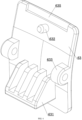
- An outer side of a bottom portion of the sleeve rod 5 is provided with a double-lock assembly 6.
- the double-lock assembly 6 includes a mounting portion 61, a pulling portion 62 for pulling and a pressing portion 63 for pressing.
- the mounting portion 61 is connected to the sleeve rod 5.
- the pulling portion 62 and the pressing portion 63 are arranged on the mounting portion 61, and the pulling portion 62 is located above the pressing portion 63. When the pulling portion is not pulled upward, the pulling portion 62 blocks the pressing portion 63.
- An inner side of the pressing portion 63 is provided with a clamping portion 631.
- An outer side of a lower portion of the support rod 4 is provided with a plurality of clamping slots 41 arranged vertically. The clamping portion 631 passes through the mounting portion 61 and the sleeve rod 5 to be clamped into the clamping slot 41.
- a mounting slot 611 is provided on an outer side of the mounting portion 61.
- An inner side of the pulling portion 62 is provided with a spring mounting seat 621 located in the mounting slot 611 and two side plates 622 spaced apart.
- the spring mounting seat 621 is provided between the two side plates 622.
- the two side plates 622 are respectively provided with strip slots 623.
- a first pin connected to the mounting portion 61 passes through the strip slots 623 of the two side plates 622.
- Middle portions of two sides of the pulling portion 62 are respectively provided with upper clamping edge portions 624, and an upper portion of the mounting portion 61 is provided with two lower clamping edge portions 612.
- Each of the lower clamping edge portions 612 is corresponding to one upper clamping edge portion 624, and the upper clamping edge portions 624 are able to abut against the lower clamping edge portions 612, respectively.
- a first spring 625 is provided between the spring mounting seat 621 and an inner top surface of the mounting slot 611. The pulling portion 62 is able to be pulled upward, and when the pulling portion 62 is not pulled upward, the upper clamping edge portions 624 respectively abut against the lower clamping edge portions 612.
- an inner side of the pressing portion 63 is provided with a spring mounting post 632 and two hinge portions 633 spaced apart.
- a second pin hinged to the mounting portion 61 passes through the two hinge portions 633.
- the mounting slot 611 is internally provided with a spring slot 613.
- a second spring 634 is provided between the spring slot 613 and the spring mounting post 632.
- the spring mounting post 632, the two hinge portions 633 and the clamping portion 631 are respectively located at upper, middle and lower portions of the inner side of the pressing portion 63.
- a bottom portion of an inner side of the pulling portion 62 is provided with an abutting portion 626.
- a top portion of the inner side of the pressing portion 63 is provided with an abutting slot 635 adapted to the abutting portion 626.
- an outer side of the abutting portion 626 abuts against an inner side of the abutting slot 635.
- the pressing portion 63 When the upper half of the pressing portion 63 is pressed, a lower half of the pressing portion 63 moves outward, such that the clamping portion 631 is disengaged from the clamping slot 41 matched with the support rod 4. At this time, the height of the sleeve rod 5 can be adjusted. When the sleeve rod 5 is adjusted to a desired height, the pressing portion 63 is released. The pressing portion 63 automatically returns under the action of the second spring 634, and the clamping portion 631 is clamped into a new clamping slot 41. Then, the pulling portion 62 is released, and the pulling portion 62 returns automatically under the action of the first spring 625. After the lifting portion 62 automatically returns, the outer side of the abutting portion 626 and the inner side of the abutting slot 635 abut against each other again.
- the bottom portion of the sleeve rod 5 is internally provided with a sleeve piece 7 through which the support rod 4 passes.
- the sleeve piece 7 is connected to the mounting portion 61.
- the outer side of the bottom portion of the sleeve rod 5 is provided with a first notch 51 for accommodating a joint between the sleeve piece 7 and the mounting portion 61.
- the sleeve piece 7 and the mounting portion 61 are integrally formed.
- the base 3 includes an outer tube 31, an intermediate tube 32 and an inner tube 33.
- the intermediate tube 32 is fixed in the outer tube 31.
- One end of the inner tube 33 is located in the intermediate tube 32, and the other end of the inner tube 33 extends out of the outer tube 31 and is fixedly connected to one end of a connecting piece 34.
- the inner tube 33 is retractable relative to the intermediate tube 32.
- the connecting piece 34 is internally provided with an elastic piece slot (not shown in the figure).
- a top surface of the connecting piece 34 is provided with a clamping hole 341.
- the elastic piece slot (not shown in the figure) is internally provided with a V-shaped elastic piece 35.
- the V-shaped elastic piece 35 is provided with a clamping head 351.
- the clamping head 351 protrudes out of the clamping hole 341 and is located at one side of the outer tube 31.
- the intermediate tube 32 is internally provided with a third spring 36 abutting against the one end of the inner tube 33.
- the connecting piece 34 and the inner tube 33 are retractable.
- the clamping head 351 of the V-shaped elastic piece 35 is pressed such that the clamping head 351 does not abut against the one side of the outer tube 31.
- the connecting piece 34 and the inner tube 33 can be retracted.
- the crib is tied to the adult bed tightly with a strap.
- the strap is loosened.
- the connecting piece 34 and the inner tube 33 automatically return to their original positions, and the clamping head 351 of the V-shaped elastic piece 35 is re-clamped into the clamping hole 341.
- the outer tube 31 is provided with an arc-shaped bottom surface.
- Each of one end of the outer tube 31 and the other end of the connecting piece 34 is provided with a rotatable caster 37.
- each of the one end of the outer tube 31 and the other end of the connecting piece 34 is provided with a second notch 38.
- Each of the one end of the outer tube 31 and the other end of the connecting piece 34 is internally provided with a pivoting assembly 8.
- the pivoting assembly 8 includes a rotating member 81 and a sliding member 82. A top portion of the caster 37 is connected to the rotating member 81.
- the rotating member 81 is correspondingly hinged to the outer tube 31/connecting piece 34.
- An outer periphery of the rotating member 81 is provided with two sockets 811 spaced apart.
- the rotating member 81 is located in the second notch 38.
- the sliding member 82 is provided with an insertion portion 821 and a sliding button 822.
- the insertion portion 821 is able to be inserted into the socket 811.
- the sliding button 822 protrudes out of the outer tube 31/connecting piece 34.
- Each of the one end of the outer tube 31 and the other end of the connecting piece 34 is internally provided with a fourth spring 823 abutting against the sliding member 82.
- the crib of the present invention can be used as an ordinary crib or a rocking crib.
- the caster 37 is in contact with a ground.
- the sliding button 822 is slid such that the insertion portion 821 is disengaged from the matched socket 811. Then, the caster 37 is rotated by a certain angle, and the sliding button 822 is released to allow the insertion portion 821 to be inserted into the other socket 811. At this time, the caster 37 is disengaged from the ground, and the bottom surface of the outer tube 31 is in contact with the ground. Since the bottom surface of the outer tube 31 is an arc-shaped surface, the crib can be rocked.
- the sleeping basket includes an upper enclosure frame 9, a support frame 10 and an enclosure cloth (not shown in the figure).
- the upper enclosure frame 9 is provided above the support frame 10.
- the enclosure cloth (not shown in the figure) is provided between the upper enclosure frame 9 and the support frame 10.
- the connection relationship between the enclosure cloth (not shown in the figure) and the upper enclosure frame 9 and the support frame 10 is in the prior art, and will not be repeated herein.
- the upper enclosure frame 9 includes a U-shaped tube 91, a left connecting tube 92, a right connecting tube 93 and a detachable tube 94.
- Two ends of the U-shaped tube 91 respectively pass through a top portion of the sleeve rod 5 of the left support portion 1 and a top portion of the sleeve rod 5 of the right support portion 2 to be respectively connected to the left connecting tube 92 and the right connecting tube 93.
- the detachable tube 94 is detachably provided between the left connecting tube 92 and the right connecting tube 93.
- Each of two ends of the detachable tube 94 is internally provided with a movable member 95 and a fifth spring 96.
- the movable member 95 has a bottom portion provided with a push portion 97, one end surface provided with an insertion rod 98 and the other end surface abutting against the fifth spring 96.
- An end surface of each of the left connecting tube 92 and the right connecting tube 93 is provided with an insertion slot 99 for the insertion of the insertion rod 98.
- An end portion of each of the left connecting tube 92 and the right connecting tube 93 is provided with a positioning portion 90.
- Each of two ends of the detachable tube 94 is provided with a positioning slot 941 adapted to the positioning portion 90.
- the detachable tube 94 is detachable from the left connecting tube 92 and the right connecting tube 93. To do so, first, the push portions 97 are pushed to disengage the insertion rods 98 from the insertion slots 99. Then, the detachable tube 94 is raised such that the positioning portions 90 are disengaged from the positioning slots 941.
Landscapes
- Mutual Connection Of Rods And Tubes (AREA)
- Invalid Beds And Related Equipment (AREA)
- Purses, Travelling Bags, Baskets, Or Suitcases (AREA)
Claims (9)
- Kinderbett, umfassend einen linken Stützabschnitt (1), einen rechten Stützabschnitt (2) und einen Schlafkorb, wobei sowohl der linke Stützabschnitt (1) als auch der rechte Stützabschnitt (2) eine Basis (3), eine Stützstange (4) und eine Hülsenstange (5) umfassen, die Stützstange (4) mit einem unterseitigen Abschnitt versehen ist, der mit einem oberseitigen Abschnitt der Basis (3) verbunden ist, und einem oberen Abschnitt, der in einem unteren Abschnitt der Hülsenstange (5) verschachtelt ist, der Schlafkorb zwischen der Hülsenstange (5) des linken Stützabschnitts (1) und der Hülsenstange (5) des rechten Stützabschnitts (2) bereitgestellt ist, eine Außenseite eines unterseitigen Abschnitts der Hülsenstange (5) mit einer Doppelschlossanordnung (6) versehen ist, die Doppelschlossanordnung (6) einen Montageabschnitt (61), einen Ziehabschnitt (62) zum Ziehen und einen Drückabschnitt (63) zum Drücken umfasst, der Montageabschnitt (61) mit der Hülsenstange (5) verbunden ist, der Ziehabschnitt (62) und der Drückabschnitt (63) auf dem Montageabschnitt (61) angeordnet sind und der Ziehabschnitt (62) über dem Drückabschnitt (63) befindlich ist, der Ziehabschnitt (62) den Drückabschnitt (63) blockiert, wenn der Ziehabschnitt (62) nach oben gezogen wird, eine Innenseite des Drückabschnitts (63) mit einem Festspannabschnitt (631) versehen ist, eine Außenseite eines unteren Abschnitts der Stützstange (4) mit einer Vielzahl von Festspannschlitzen (41), die vertikal angeordnet sind, versehen ist und der Festspannabschnitt (631) durch den Montageabschnitt (61) und die Hülsenstange (5) führt, um in einem Festspannschlitz (41) der Vielzahl von Festspannschlitzen (41) festgespannt zu werden,
dadurch gekennzeichnet, dass ein Montageschlitz (611) auf einer Außenseite des Montageabschnitts (61) bereitgestellt ist, eine Innenseite des Ziehabschnitts (62) mit einem Federmontagesitz (621) versehen ist, der im Montageschlitz (611) befindlich ist, sowie zwei beabstandeten Seitenplatten (622), der Federmontagesitz (621) zwischen den beiden Seitenplatten (622) bereitgestellt ist, die beiden Seitenplatten (622) jeweils mit Streifenschlitzen (623) versehen sind, ein erster Zapfen, der mit dem Montageabschnitt (61) verbunden ist, durch die Streifenschlitze (623) der beiden Seitenplatten (622) führt, mittlere Abschnitte von zwei Seiten des Ziehabschnitts (62) jeweils mit oberen Festspannkantenabschnitten (624) versehen sind, ein oberer Abschnitt des Montageabschnitts (61) mit zwei unteren Festspannkantenabschnitten (612) versehen ist und die beiden unteren Festspannkantenabschnitte (612) jeweils den oberen Festspannkantenabschnitten (624) entsprechen, die oberen Festspannkantenabschnitte (624) dazu konfiguriert sind, jeweils an den beiden unteren Festspannkantenabschnitten (612) anzuschlagen, und eine erste Feder (625) zwischen dem Federmontagesitz (621) und einer inneren oberseitigen Oberfläche des Montagesitzes (611) bereitgestellt ist. - Kinderbett nach Anspruch 1, wobei eine Innenseite des Drückabschnitts (63) mit einem Federmontageständer (632) und zwei beabstandeten Gelenkbefestigungsabschnitten (633) versehen ist, ein zweiter Zapfen, der gelenkig am Montageabschnitt (61) befestigt ist, durch die beiden Gelenkbefestigungsabschnitte (633) führt, der Montageschlitz (611) innenseitig mit einem Federschlitz (613) versehen ist, eine zweite Feder (634) zwischen dem Federschlitz (613) und der Federmontagestütze (632) bereitgestellt ist und die Federmontagestütze (632), die beiden Gelenkverbindungsabschnitte (633) und der Festspannabschnitt (631) jeweils an oberen, mittleren und unteren Abschnitten der Innenseite des Drückabschnitts (63) befindlich sind.
- Kinderbett nach Anspruch 1, wobei ein unterseitiger Abschnitt einer Innenseite des Ziehabschnitts (62) mit einem Anschlagsabschnitt (626) versehen ist, ein oberseitiger Abschnitt der Innenseite des Drückabschnitts (63) mit einem Anschlagsschlitz (635) versehen ist, der passend zum Anschlagsabschnitt (626) ausgeformt ist, und eine Außenseite des Anschlagsabschnitts (626) an einer Innenseite des Anschlagsschlitzes (635) anschlägt, wenn der Ziehabschnitt (62) nicht nach oben gezogen wird.
- Kinderbett nach Anspruch 1, wobei der untere Abschnitt der Hülsenstange (5) innenseitig mit einem Hülsenstück (7) versehen ist, wobei die Stützstange (4) durch das Hülsenstück (7) führt, das Hülsenstück (7) mit dem Montageabschnitt (61) verbunden und die Außenseite des unterseitigen Abschnitts der Hülsenstange (5) mit einer ersten Kerbe (51) versehen ist, um ein Gelenk zwischen dem Hülsenstück (7) und dem Montageabschnitt (61) unterzubringen.
- Kinderbett nach Anspruch 1, wobei die Basis (3) ein Außenrohr (31), ein Zwischenrohr (32) und ein Innenrohr (33) umfasst, das Zwischenrohr (32) im Außenrohr (31) fixiert ist, ein erstes Ende des Innenrohrs (33) im Zwischenrohr (32) befindlich ist und sich ein zweites Ende des Innenrohrs (33) aus dem Außenrohr (31) erstreckt und fix mit dem ersten Ende eines Verbindungsstücks (34) verbunden ist und das Innenrohr (33) relativ zum Zwischenrohr (32) einziehbar ist.
- Kinderbett nach Anspruch 5, wobei das Verbindungsstück (34) innenseitig mit einem Schlitz für ein elastisches Stück versehen ist, eine oberseitige Oberfläche des Verbindungsstücks (34) mit einem Festspannloch (341) versehen ist, der Schlitz für das elastische Stück innenseitig mit einem V-förmigen elastischen Stück (35) versehen ist, das V-förmige elastische Stück (35) mit einem Festspannkopf (351) versehen ist, der Festspannkopf (351) aus dem Festspannloch (341) ragt und an einer Seite des Außenrohrs (31) befindlich ist und das Zwischenrohr (32) innenseitig mit einer dritten Feder (36) versehen ist, die an das erste Ende des Innenrohrs (33) anschlägt.
- Kinderbett nach Anspruch 5, wobei das Außenrohr (31) mit einer bogenförmigen unterseitigen Oberfläche versehen ist und sowohl ein Ende des Außenrohrs (31) als auch ein zweites Ende des Verbindungsstücks (34) mit einer drehbaren Lenkrolle (37) versehen sind.
- Kinderbett nach Anspruch 7, wobei sowohl das Ende des Außenrohrs (31) als auch das zweite Ende des Verbindungsstücks (34) mit einer zweiten Kerbe (38) versehen sind, sowohl das Ende des Außenrohrs (31) als auch das zweite Ende des Verbindungsstücks (34) innenseitig mit einer Schwenkanordnung (8) versehen sind, die Schwenkanordnung (8) ein rotierendes Element (81) und ein gleitendes Element (82) umfasst, ein oberseitiger Abschnitt der drehbaren Lenkrolle (37) mit dem rotierenden Element (81) verbunden ist, das rotierende Element (81) entsprechend gelenkig am Außenrohr (31)/Verbindungsstück (34) befestigt ist, ein äußerer Umfang des rotierenden Elements (81) mit zwei beabstandeten Sockeln (811) versehen ist, das rotierende Element (81) in der zweiten Kerbe (38) befindlich ist, das gleitende Element (82) mit einem Einfügeabschnitt (821) und einem gleitenden Knopf (822) versehen ist, der Einfügeabschnitt (821) dazu konfiguriert ist, in einen Sockel (811) der beiden Sockel (811) eingefügt zu werden, der gleitende Knopf (822) aus dem Außenrohr (31)/Verbindungsstück (34) ragt und sowohl das Ende des Außenrohrs (31) als auch das zweite Ende des Verbindungsstücks (34) innenseitig mit einer vierten Feder (823) versehen sind, die am gleitenden Element (82) anschlägt.
- Kinderbett nach Anspruch 1, wobei der Schlafkorb einen oberen Einfassungsrahmen (9), einen Stützrahmen (10) und ein Einfassungsgewebe umfasst, der obere Einfassungsrahmen (9) über dem Stützrahmen (10) bereitgestellt ist, das Einfassungsgewebe zwischen dem oberen Einfassungsrahmen (9) und dem Stützrahmen (10) bereitgestellt ist, der obere Einfassungsrahmen (9) ein U-förmiges Rohr (91), ein linkes Verbindungsrohr (92), ein rechtes Verbindungsrohr (93) und ein abnehmbares Rohr (94) umfasst, zwei Enden des U-förmigen Rohrs (91) jeweils durch einen oberseitigen Abschnitt der Hülsenstange (5) des linken Stützabschnitts (1) führen und ein oberseitiger Abschnitt der Hülsenstange (5) des rechten Abschnitts (2) jeweils mit dem linken Verbindungsrohr (92) und dem rechten Verbindungsrohr (93) zu verbinden ist, das abnehmbare Rohr (94) abnehmbar zwischen dem linken Verbindungsrohr (92) und dem rechten Verbindungsrohr (93) bereitgestellt ist, ein jedes der beiden Enden des abnehmbaren Rohrs (94) innenseitig mit einem bewegbaren Element (95) und einer fünften Feder (96) versehen ist, das bewegbare Element (95) einen unterseitigen Abschnitt aufweist, der mit einem Schiebeabschnitt (97) versehen ist, eine erste Endoberfläche, die mit einer Einfügestange (98) versehen ist, und eine zweite Endoberfläche, die an die fünfte Feder (96) anschlägt, eine Endoberfläche sowohl des linken Verbindungsrohrs (92) als auch des rechten Verbindungsrohrs (93) mit einem Einfügeschlitz (99) für ein Einfügen der Einfügestange (98) versehen ist, ein Endabschnitt sowohl des linken Verbindungsrohrs (92) als auch des rechten Verbindungsrohrs (93) mit einem Positionierungsabschnitt (90) versehen ist und ein jedes der beiden Enden des abnehmbaren Rohrs (94) mit einem zum Positionierungsabschnitt (90) passenden Positionierungsschlitz (941) versehen ist.
Applications Claiming Priority (1)
| Application Number | Priority Date | Filing Date | Title |
|---|---|---|---|
| CN202123362485.3U CN217185437U (zh) | 2021-12-29 | 2021-12-29 | 一种小睡床 |
Publications (2)
| Publication Number | Publication Date |
|---|---|
| EP4205605A1 EP4205605A1 (de) | 2023-07-05 |
| EP4205605B1 true EP4205605B1 (de) | 2024-10-09 |
Family
ID=82492608
Family Applications (1)
| Application Number | Title | Priority Date | Filing Date |
|---|---|---|---|
| EP22182362.8A Active EP4205605B1 (de) | 2021-12-29 | 2022-06-30 | Kleinkindbett |
Country Status (3)
| Country | Link |
|---|---|
| US (1) | US12446708B2 (de) |
| EP (1) | EP4205605B1 (de) |
| CN (1) | CN217185437U (de) |
Cited By (1)
| Publication number | Priority date | Publication date | Assignee | Title |
|---|---|---|---|---|
| US12357107B2 (en) * | 2022-04-28 | 2025-07-15 | TJ(fujian) Industrial Co., Ltd. | Crib |
Families Citing this family (10)
| Publication number | Priority date | Publication date | Assignee | Title |
|---|---|---|---|---|
| CN214018584U (zh) * | 2020-12-21 | 2021-08-24 | 福建童匠实业有限公司 | 一种折叠升降收合的消毒盒 |
| USD1048789S1 (en) * | 2021-06-01 | 2024-10-29 | Skip Hop, Inc. | Bedside sleeper |
| USD1011070S1 (en) * | 2021-12-29 | 2024-01-16 | TJ(fujian) Industrial Co., Ltd. | Bassinet |
| USD1011069S1 (en) * | 2022-04-06 | 2024-01-16 | Dezhu Ou | Baby bed |
| USD1021450S1 (en) * | 2022-04-28 | 2024-04-09 | TJ(fujian) Industrial Co., Ltd. | Bassinet |
| USD1036882S1 (en) * | 2022-07-08 | 2024-07-30 | Zhongshan City Bobie Baby Product Co., Ltd. | Baby bed |
| USD1028556S1 (en) * | 2022-10-06 | 2024-05-28 | Zhongshan Yongda Baby Products Co.?Ltd. | Crib |
| USD1028593S1 (en) * | 2022-10-17 | 2024-05-28 | Zhongshan M-Castle Childrens Product Co., Ltd. | Foldable bedside sleeper |
| USD1017269S1 (en) * | 2023-11-14 | 2024-03-12 | Zhouhao Li | Bassinet |
| USD1049686S1 (en) * | 2024-07-16 | 2024-11-05 | Yuxi Jiang | Bassinet |
Family Cites Families (10)
| Publication number | Priority date | Publication date | Assignee | Title |
|---|---|---|---|---|
| CN104720437B (zh) * | 2013-12-20 | 2017-10-10 | 明门香港股份有限公司 | 婴儿照顾装置 |
| CN105559431B (zh) * | 2014-10-15 | 2018-09-25 | 明门香港股份有限公司 | 车架高度调整机构及车架 |
| CN207370408U (zh) * | 2017-01-06 | 2018-05-18 | 厦门梦贝比儿童用品有限公司 | 一种婴儿床 |
| US11259651B2 (en) * | 2017-09-30 | 2022-03-01 | Bambino Prezioso Switzerland Ag | Child accommodating apparatus with an armrest rotating mechanism |
| CN209750534U (zh) * | 2018-11-21 | 2019-12-10 | 明门(中国)幼童用品有限公司 | 童床 |
| CN209898878U (zh) * | 2019-01-22 | 2020-01-07 | 福建欧仕儿童用品股份有限公司 | 一种可折叠的床边床 |
| US11700953B2 (en) * | 2019-09-18 | 2023-07-18 | Wonderland Switzerland Ag | Child care apparatus |
| CN212546366U (zh) * | 2019-12-24 | 2021-02-19 | 中童(厦门)婴童智能家居有限公司 | 一种可升降的婴儿睡床架 |
| WO2021225943A1 (en) * | 2020-05-04 | 2021-11-11 | Tuckey Peter R | Bedside bassinet assembly |
| CN218074270U (zh) * | 2022-04-28 | 2022-12-20 | 福建童匠实业有限公司 | 一种新型的小睡床 |
-
2021
- 2021-12-29 CN CN202123362485.3U patent/CN217185437U/zh active Active
-
2022
- 2022-06-30 EP EP22182362.8A patent/EP4205605B1/de active Active
- 2022-12-29 US US18/090,556 patent/US12446708B2/en active Active
Cited By (1)
| Publication number | Priority date | Publication date | Assignee | Title |
|---|---|---|---|---|
| US12357107B2 (en) * | 2022-04-28 | 2025-07-15 | TJ(fujian) Industrial Co., Ltd. | Crib |
Also Published As
| Publication number | Publication date |
|---|---|
| US12446708B2 (en) | 2025-10-21 |
| CN217185437U (zh) | 2022-08-16 |
| US20230200558A1 (en) | 2023-06-29 |
| EP4205605A1 (de) | 2023-07-05 |
Similar Documents
| Publication | Publication Date | Title |
|---|---|---|
| EP4205605B1 (de) | Kleinkindbett | |
| AU2023233154B2 (en) | Handle adjustment mechanism and child crib therewith | |
| CN103202634B (zh) | 婴儿床 | |
| US12357107B2 (en) | Crib | |
| US11730284B2 (en) | Multipurpose bassinet | |
| EP4205604B1 (de) | Multifunktionskrippe | |
| EP2409605B1 (de) | Babybett | |
| CN108294553A (zh) | 旅行用幼儿摇篮 | |
| CN110811217A (zh) | 婴儿床及其应用 | |
| US12419439B2 (en) | Bassinet | |
| CN114732250A (zh) | 婴儿床架以及婴儿床 | |
| CN107616642A (zh) | 床边床及其扶手调整机构 | |
| CN214258723U (zh) | 折叠式婴儿床边床 | |
| CN212546366U (zh) | 一种可升降的婴儿睡床架 | |
| CN106579867B (zh) | 便携式儿童座位安装椅 | |
| CN216416629U (zh) | 一种多功能床边床 | |
| CN222917238U (zh) | 一种婴儿摇床 | |
| CN222804116U (zh) | 一种婴儿床架 | |
| CN220713484U (zh) | 婴儿睡篮及婴儿床 | |
| CN221083243U (zh) | 一种易升降的儿童床架 | |
| CN223323268U (zh) | 一种婴儿护理装置 | |
| CN222548934U (zh) | 一种婴儿学步车 | |
| CN218551912U (zh) | 高度可调的婴儿床 | |
| CN220824108U (zh) | 具备有拉杆装置的婴儿床 | |
| CN215077037U (zh) | 一种易折叠收纳的床边床 |
Legal Events
| Date | Code | Title | Description |
|---|---|---|---|
| PUAI | Public reference made under article 153(3) epc to a published international application that has entered the european phase |
Free format text: ORIGINAL CODE: 0009012 |
|
| STAA | Information on the status of an ep patent application or granted ep patent |
Free format text: STATUS: REQUEST FOR EXAMINATION WAS MADE |
|
| 17P | Request for examination filed |
Effective date: 20220630 |
|
| AK | Designated contracting states |
Kind code of ref document: A1 Designated state(s): AL AT BE BG CH CY CZ DE DK EE ES FI FR GB GR HR HU IE IS IT LI LT LU LV MC MK MT NL NO PL PT RO RS SE SI SK SM TR |
|
| GRAP | Despatch of communication of intention to grant a patent |
Free format text: ORIGINAL CODE: EPIDOSNIGR1 |
|
| STAA | Information on the status of an ep patent application or granted ep patent |
Free format text: STATUS: GRANT OF PATENT IS INTENDED |
|
| INTG | Intention to grant announced |
Effective date: 20240503 |
|
| GRAS | Grant fee paid |
Free format text: ORIGINAL CODE: EPIDOSNIGR3 |
|
| GRAA | (expected) grant |
Free format text: ORIGINAL CODE: 0009210 |
|
| STAA | Information on the status of an ep patent application or granted ep patent |
Free format text: STATUS: THE PATENT HAS BEEN GRANTED |
|
| AK | Designated contracting states |
Kind code of ref document: B1 Designated state(s): AL AT BE BG CH CY CZ DE DK EE ES FI FR GB GR HR HU IE IS IT LI LT LU LV MC MK MT NL NO PL PT RO RS SE SI SK SM TR |
|
| REG | Reference to a national code |
Ref country code: CH Ref legal event code: EP |
|
| REG | Reference to a national code |
Ref country code: DE Ref legal event code: R096 Ref document number: 602022006630 Country of ref document: DE |
|
| REG | Reference to a national code |
Ref country code: IE Ref legal event code: FG4D |
|
| REG | Reference to a national code |
Ref country code: LT Ref legal event code: MG9D |
|
| REG | Reference to a national code |
Ref country code: NL Ref legal event code: MP Effective date: 20241009 |
|
| REG | Reference to a national code |
Ref country code: AT Ref legal event code: MK05 Ref document number: 1729596 Country of ref document: AT Kind code of ref document: T Effective date: 20241009 |
|
| PG25 | Lapsed in a contracting state [announced via postgrant information from national office to epo] |
Ref country code: NL Free format text: LAPSE BECAUSE OF FAILURE TO SUBMIT A TRANSLATION OF THE DESCRIPTION OR TO PAY THE FEE WITHIN THE PRESCRIBED TIME-LIMIT Effective date: 20241009 |
|
| PG25 | Lapsed in a contracting state [announced via postgrant information from national office to epo] |
Ref country code: NL Free format text: LAPSE BECAUSE OF FAILURE TO SUBMIT A TRANSLATION OF THE DESCRIPTION OR TO PAY THE FEE WITHIN THE PRESCRIBED TIME-LIMIT Effective date: 20241009 |
|
| PG25 | Lapsed in a contracting state [announced via postgrant information from national office to epo] |
Ref country code: HR Free format text: LAPSE BECAUSE OF FAILURE TO SUBMIT A TRANSLATION OF THE DESCRIPTION OR TO PAY THE FEE WITHIN THE PRESCRIBED TIME-LIMIT Effective date: 20241009 Ref country code: PT Free format text: LAPSE BECAUSE OF FAILURE TO SUBMIT A TRANSLATION OF THE DESCRIPTION OR TO PAY THE FEE WITHIN THE PRESCRIBED TIME-LIMIT Effective date: 20250210 Ref country code: IS Free format text: LAPSE BECAUSE OF FAILURE TO SUBMIT A TRANSLATION OF THE DESCRIPTION OR TO PAY THE FEE WITHIN THE PRESCRIBED TIME-LIMIT Effective date: 20250209 |
|
| PG25 | Lapsed in a contracting state [announced via postgrant information from national office to epo] |
Ref country code: FI Free format text: LAPSE BECAUSE OF FAILURE TO SUBMIT A TRANSLATION OF THE DESCRIPTION OR TO PAY THE FEE WITHIN THE PRESCRIBED TIME-LIMIT Effective date: 20241009 |
|
| PG25 | Lapsed in a contracting state [announced via postgrant information from national office to epo] |
Ref country code: BG Free format text: LAPSE BECAUSE OF FAILURE TO SUBMIT A TRANSLATION OF THE DESCRIPTION OR TO PAY THE FEE WITHIN THE PRESCRIBED TIME-LIMIT Effective date: 20241009 |
|
| PG25 | Lapsed in a contracting state [announced via postgrant information from national office to epo] |
Ref country code: ES Free format text: LAPSE BECAUSE OF FAILURE TO SUBMIT A TRANSLATION OF THE DESCRIPTION OR TO PAY THE FEE WITHIN THE PRESCRIBED TIME-LIMIT Effective date: 20241009 |
|
| PG25 | Lapsed in a contracting state [announced via postgrant information from national office to epo] |
Ref country code: NO Free format text: LAPSE BECAUSE OF FAILURE TO SUBMIT A TRANSLATION OF THE DESCRIPTION OR TO PAY THE FEE WITHIN THE PRESCRIBED TIME-LIMIT Effective date: 20250109 |
|
| PG25 | Lapsed in a contracting state [announced via postgrant information from national office to epo] |
Ref country code: AT Free format text: LAPSE BECAUSE OF FAILURE TO SUBMIT A TRANSLATION OF THE DESCRIPTION OR TO PAY THE FEE WITHIN THE PRESCRIBED TIME-LIMIT Effective date: 20241009 Ref country code: LV Free format text: LAPSE BECAUSE OF FAILURE TO SUBMIT A TRANSLATION OF THE DESCRIPTION OR TO PAY THE FEE WITHIN THE PRESCRIBED TIME-LIMIT Effective date: 20241009 Ref country code: GR Free format text: LAPSE BECAUSE OF FAILURE TO SUBMIT A TRANSLATION OF THE DESCRIPTION OR TO PAY THE FEE WITHIN THE PRESCRIBED TIME-LIMIT Effective date: 20250110 |
|
| PG25 | Lapsed in a contracting state [announced via postgrant information from national office to epo] |
Ref country code: PL Free format text: LAPSE BECAUSE OF FAILURE TO SUBMIT A TRANSLATION OF THE DESCRIPTION OR TO PAY THE FEE WITHIN THE PRESCRIBED TIME-LIMIT Effective date: 20241009 |
|
| PG25 | Lapsed in a contracting state [announced via postgrant information from national office to epo] |
Ref country code: RS Free format text: LAPSE BECAUSE OF FAILURE TO SUBMIT A TRANSLATION OF THE DESCRIPTION OR TO PAY THE FEE WITHIN THE PRESCRIBED TIME-LIMIT Effective date: 20250109 |
|
| PG25 | Lapsed in a contracting state [announced via postgrant information from national office to epo] |
Ref country code: SM Free format text: LAPSE BECAUSE OF FAILURE TO SUBMIT A TRANSLATION OF THE DESCRIPTION OR TO PAY THE FEE WITHIN THE PRESCRIBED TIME-LIMIT Effective date: 20241009 |
|
| PGFP | Annual fee paid to national office [announced via postgrant information from national office to epo] |
Ref country code: DE Payment date: 20250624 Year of fee payment: 4 |
|
| PG25 | Lapsed in a contracting state [announced via postgrant information from national office to epo] |
Ref country code: DK Free format text: LAPSE BECAUSE OF FAILURE TO SUBMIT A TRANSLATION OF THE DESCRIPTION OR TO PAY THE FEE WITHIN THE PRESCRIBED TIME-LIMIT Effective date: 20241009 |
|
| REG | Reference to a national code |
Ref country code: DE Ref legal event code: R097 Ref document number: 602022006630 Country of ref document: DE |
|
| PG25 | Lapsed in a contracting state [announced via postgrant information from national office to epo] |
Ref country code: EE Free format text: LAPSE BECAUSE OF FAILURE TO SUBMIT A TRANSLATION OF THE DESCRIPTION OR TO PAY THE FEE WITHIN THE PRESCRIBED TIME-LIMIT Effective date: 20241009 |
|
| PGFP | Annual fee paid to national office [announced via postgrant information from national office to epo] |
Ref country code: FR Payment date: 20250618 Year of fee payment: 4 |
|
| PG25 | Lapsed in a contracting state [announced via postgrant information from national office to epo] |
Ref country code: RO Free format text: LAPSE BECAUSE OF FAILURE TO SUBMIT A TRANSLATION OF THE DESCRIPTION OR TO PAY THE FEE WITHIN THE PRESCRIBED TIME-LIMIT Effective date: 20241009 |
|
| PG25 | Lapsed in a contracting state [announced via postgrant information from national office to epo] |
Ref country code: SK Free format text: LAPSE BECAUSE OF FAILURE TO SUBMIT A TRANSLATION OF THE DESCRIPTION OR TO PAY THE FEE WITHIN THE PRESCRIBED TIME-LIMIT Effective date: 20241009 |
|
| PG25 | Lapsed in a contracting state [announced via postgrant information from national office to epo] |
Ref country code: CZ Free format text: LAPSE BECAUSE OF FAILURE TO SUBMIT A TRANSLATION OF THE DESCRIPTION OR TO PAY THE FEE WITHIN THE PRESCRIBED TIME-LIMIT Effective date: 20241009 |
|
| PG25 | Lapsed in a contracting state [announced via postgrant information from national office to epo] |
Ref country code: IT Free format text: LAPSE BECAUSE OF FAILURE TO SUBMIT A TRANSLATION OF THE DESCRIPTION OR TO PAY THE FEE WITHIN THE PRESCRIBED TIME-LIMIT Effective date: 20241009 |
|
| PLBE | No opposition filed within time limit |
Free format text: ORIGINAL CODE: 0009261 |
|
| STAA | Information on the status of an ep patent application or granted ep patent |
Free format text: STATUS: NO OPPOSITION FILED WITHIN TIME LIMIT |
|
| PG25 | Lapsed in a contracting state [announced via postgrant information from national office to epo] |
Ref country code: SE Free format text: LAPSE BECAUSE OF FAILURE TO SUBMIT A TRANSLATION OF THE DESCRIPTION OR TO PAY THE FEE WITHIN THE PRESCRIBED TIME-LIMIT Effective date: 20241009 |
|
| 26N | No opposition filed |
Effective date: 20250710 |
|
| REG | Reference to a national code |
Ref country code: CH Ref legal event code: H13 Free format text: ST27 STATUS EVENT CODE: U-0-0-H10-H13 (AS PROVIDED BY THE NATIONAL OFFICE) Effective date: 20260127 |
|
| PG25 | Lapsed in a contracting state [announced via postgrant information from national office to epo] |
Ref country code: MC Free format text: LAPSE BECAUSE OF FAILURE TO SUBMIT A TRANSLATION OF THE DESCRIPTION OR TO PAY THE FEE WITHIN THE PRESCRIBED TIME-LIMIT Effective date: 20241009 |
|
| PG25 | Lapsed in a contracting state [announced via postgrant information from national office to epo] |
Ref country code: LU Free format text: LAPSE BECAUSE OF NON-PAYMENT OF DUE FEES Effective date: 20250630 |
|
| REG | Reference to a national code |
Ref country code: BE Ref legal event code: MM Effective date: 20250630 |
|
| PG25 | Lapsed in a contracting state [announced via postgrant information from national office to epo] |
Ref country code: IE Free format text: LAPSE BECAUSE OF NON-PAYMENT OF DUE FEES Effective date: 20250630 |
|
| PG25 | Lapsed in a contracting state [announced via postgrant information from national office to epo] |
Ref country code: BE Free format text: LAPSE BECAUSE OF NON-PAYMENT OF DUE FEES Effective date: 20250630 |
|
| PG25 | Lapsed in a contracting state [announced via postgrant information from national office to epo] |
Ref country code: CH Free format text: LAPSE BECAUSE OF NON-PAYMENT OF DUE FEES Effective date: 20250630 |