EP4205671B1 - Systeme zur einführung einer medizinischen vorrichtung mit twist-loop-drähten - Google Patents
Systeme zur einführung einer medizinischen vorrichtung mit twist-loop-drähten Download PDFInfo
- Publication number
- EP4205671B1 EP4205671B1 EP22217254.6A EP22217254A EP4205671B1 EP 4205671 B1 EP4205671 B1 EP 4205671B1 EP 22217254 A EP22217254 A EP 22217254A EP 4205671 B1 EP4205671 B1 EP 4205671B1
- Authority
- EP
- European Patent Office
- Prior art keywords
- wire
- loop
- pull wire
- opening
- distal
- Prior art date
- Legal status (The legal status is an assumption and is not a legal conclusion. Google has not performed a legal analysis and makes no representation as to the accuracy of the status listed.)
- Active
Links
Images




Classifications
-
- A—HUMAN NECESSITIES
- A61—MEDICAL OR VETERINARY SCIENCE; HYGIENE
- A61B—DIAGNOSIS; SURGERY; IDENTIFICATION
- A61B17/00—Surgical instruments, devices or methods
- A61B17/12—Surgical instruments, devices or methods for ligaturing or otherwise compressing tubular parts of the body, e.g. blood vessels or umbilical cord
- A61B17/12022—Occluding by internal devices, e.g. balloons or releasable wires
- A61B17/12131—Occluding by internal devices, e.g. balloons or releasable wires characterised by the type of occluding device
- A61B17/1214—Coils or wires
-
- A—HUMAN NECESSITIES
- A61—MEDICAL OR VETERINARY SCIENCE; HYGIENE
- A61B—DIAGNOSIS; SURGERY; IDENTIFICATION
- A61B17/00—Surgical instruments, devices or methods
- A61B17/04—Surgical instruments, devices or methods for suturing wounds; Holders or packages for needles or suture materials
- A61B17/06—Needles ; Sutures; Needle-suture combinations; Holders or packages for needles or suture materials
- A61B17/06166—Sutures
-
- A—HUMAN NECESSITIES
- A61—MEDICAL OR VETERINARY SCIENCE; HYGIENE
- A61B—DIAGNOSIS; SURGERY; IDENTIFICATION
- A61B17/00—Surgical instruments, devices or methods
- A61B17/12—Surgical instruments, devices or methods for ligaturing or otherwise compressing tubular parts of the body, e.g. blood vessels or umbilical cord
- A61B17/12022—Occluding by internal devices, e.g. balloons or releasable wires
-
- A—HUMAN NECESSITIES
- A61—MEDICAL OR VETERINARY SCIENCE; HYGIENE
- A61B—DIAGNOSIS; SURGERY; IDENTIFICATION
- A61B17/00—Surgical instruments, devices or methods
- A61B17/12—Surgical instruments, devices or methods for ligaturing or otherwise compressing tubular parts of the body, e.g. blood vessels or umbilical cord
- A61B17/12022—Occluding by internal devices, e.g. balloons or releasable wires
- A61B17/12099—Occluding by internal devices, e.g. balloons or releasable wires characterised by the location of the occluder
- A61B17/12109—Occluding by internal devices, e.g. balloons or releasable wires characterised by the location of the occluder in a blood vessel
- A61B17/12113—Occluding by internal devices, e.g. balloons or releasable wires characterised by the location of the occluder in a blood vessel within an aneurysm
-
- A—HUMAN NECESSITIES
- A61—MEDICAL OR VETERINARY SCIENCE; HYGIENE
- A61B—DIAGNOSIS; SURGERY; IDENTIFICATION
- A61B17/00—Surgical instruments, devices or methods
- A61B2017/00526—Methods of manufacturing
-
- A—HUMAN NECESSITIES
- A61—MEDICAL OR VETERINARY SCIENCE; HYGIENE
- A61B—DIAGNOSIS; SURGERY; IDENTIFICATION
- A61B17/00—Surgical instruments, devices or methods
- A61B2017/00831—Material properties
- A61B2017/00858—Material properties high friction or non-slip
-
- A—HUMAN NECESSITIES
- A61—MEDICAL OR VETERINARY SCIENCE; HYGIENE
- A61B—DIAGNOSIS; SURGERY; IDENTIFICATION
- A61B17/00—Surgical instruments, devices or methods
- A61B17/04—Surgical instruments, devices or methods for suturing wounds; Holders or packages for needles or suture materials
- A61B17/06—Needles ; Sutures; Needle-suture combinations; Holders or packages for needles or suture materials
- A61B17/06166—Sutures
- A61B2017/0618—Sutures elastic, e.g. stretchable
-
- A—HUMAN NECESSITIES
- A61—MEDICAL OR VETERINARY SCIENCE; HYGIENE
- A61B—DIAGNOSIS; SURGERY; IDENTIFICATION
- A61B17/00—Surgical instruments, devices or methods
- A61B17/12—Surgical instruments, devices or methods for ligaturing or otherwise compressing tubular parts of the body, e.g. blood vessels or umbilical cord
- A61B17/12022—Occluding by internal devices, e.g. balloons or releasable wires
- A61B2017/1205—Introduction devices
-
- A—HUMAN NECESSITIES
- A61—MEDICAL OR VETERINARY SCIENCE; HYGIENE
- A61B—DIAGNOSIS; SURGERY; IDENTIFICATION
- A61B17/00—Surgical instruments, devices or methods
- A61B17/12—Surgical instruments, devices or methods for ligaturing or otherwise compressing tubular parts of the body, e.g. blood vessels or umbilical cord
- A61B17/12022—Occluding by internal devices, e.g. balloons or releasable wires
- A61B2017/1205—Introduction devices
- A61B2017/12054—Details concerning the detachment of the occluding device from the introduction device
Definitions
- This disclosure generally relates to intravascular medical device systems that navigate through body vessels of a human subject and, more particularly, to detachment/delivery systems for delivering and deploying an implantable medical device to a target location of a body vessel.
- Aneurysms can be intravascularly treated by delivering a treatment device to the aneurysm to fill the sac of the aneurysm with embolic material and/or block the neck of the aneurysm to inhibit blood flow into the aneurysm.
- the embolic material can promote blood clotting to create a thrombotic mass within the aneurysm.
- blood flow into the neck of the aneurysm can be inhibited to induce venous stasis in the aneurysm and facilitate natural formation of a thrombotic mass within the aneurysm.
- embolic coils are used to either fill the aneurysm sac or treat the entrance of the aneurysm neck.
- a common challenge among embolic coil treatments is that implanted coils and implanted portions of partially implanted coils can become entangled and difficult to reposition.
- a physician may not be able to retract a partially implanted coil and may be forced to position the coil in a non-ideal location. Improperly positioning embolic coils at the aneurysm neck can potentially have the adverse effect of impeding the flow of blood in the adjoining blood vessel, particularly if the entrance and/or sac is overpacked.
- an embolic coil is attached to a tubular delivery device and delivered via a delivery catheter to an aneurysm.
- the embolic coil can be engaged to the delivery member's implant detachment/deployment system (referred to herein equivalently as an "detachment system” or “deployment system”).
- the deployment system can release the coil, the coil can be left implanted, and the delivery member can be retracted.
- Some treatments utilize a mechanical detachment/deployment system that can be actuated by a physician to release the implant by pulling one or more wires or other elongated members referred to generically herein as a "pull wire.”
- Some of the challenges that have been associated with delivering and deploying embolic coils with delivery members having mechanical detachment systems include premature release of a coil due to premature movement of the pull wire proximally, thereby releasing the coil before the system is at the treatment site. This is exacerbated because of the system moves through tortuous vasculature to the treatment site.
- EP3560439A1 provides a detachment system for delivering an implantable medical device to a target location of a body vessel that has a generally hollow distal tube.
- the distal tube includes a proximal end, a distal end, and a compressible portion of the tube itself, between the proximal and distal ends which is axially movable from a compressed to an elongated condition.
- a generally hollow proximal tube has a proximal end and a distal end.
- An engagement system engages and deploys the implantable medical device engaged at the distal end of the distal tube. The engagement system moves the compressible portion to the compressed condition when engaging the implantable medical device, and deploys the implantable medical device and releases the compressible portion to the elongated condition.
- WO2016/014985A1 relates to embolic implants for use in the minimally-invasive treatment of aneurysms and other vascular disorders.
- premature proximal movement or translation of a pull wire can be decreased by providing a loop wire that twists one or more times around the pull wire, thereby providing a greater amount of friction against the pull wire.
- a detachment system for delivering an implantable medical device to a target location of a body vessel can include a tubular body comprising a lumen extending therethrough and a compressed distal tube.
- the detachment system can include a loop wire comprising a first end attachment and a second end attachment affixed to the tubular body.
- the loop wire can further include a loop opening positioned proximate a distal end of the compressed distal tube.
- the detachment system can include a pull wire extending through the lumen and through the loop opening.
- the loop wire can include a twist such that that the loop wire is twisted at least one time around the pull wire to increase friction between the loop wire and the pull wire.
- the twist can inhibit premature detachment of the implantable medical device by inhibiting proximal translation of the pull wire due to frictional resistance provided by the loop wire via the twist.
- the tubular body can include a flexible coil disposed in a proximal direction from the compressed distal tube.
- the loop wire can inhibit elongation of the flexible coil when looped over the pull wire.
- the detachment system can include a key affixed to the implantable medical device proximate a proximal end of the implantable medical device.
- the detachment system can include a stretch resistant fiber engaged to the key, extended through an implant lumen of the implantable medical device, and affixed to the implantable medical device proximate a distal end of the implantable medical device.
- the key can include a distal opening therethrough, wherein the stretch resistant fiber passes through the distal opening.
- the key can include a proximal opening therethrough.
- the key can include a bridge separating the distal opening and the proximal opening. The bridge can support a portion of the pull wire in a distal direction from the loop opening. The twist can be positioned on the loop wire proximal to the bridge.
- the pull wire can be weaved across the bridge such that the pull wire passes from a first side of the key, through the proximal opening to a second side of the key and across the bridge, and through the distal opening to the first side of the key.
- a detachment system for delivering an implantable medical device to a target location of a body vessel can include a pull wire extending through a tubular body of the detachment system.
- the detachment system can include a loop wire looped over the pull wire at a distal end of the loop wire and twisted at least once around the pull wire.
- a twist in the loop wire can inhibit premature detachment of the implantable medical device by inhibiting proximal translation of the pull wire relative to a loop opening in the distal end of the loop wire.
- the loop wire can be twisted a single time around the pull wire, while in other examples the loop wire can be twisted a plurality of times around the pull wire. Additional twists can increase the friction/tightness of the junction between the pull wire and the loop wire.
- the detachment system can include a compressed distal tube.
- the tubular body can include a flexible coil disposed in a proximal direction from the compressed distal tube.
- the loop wire can inhibit elongation of the flexible coil when looped over the pull wire.
- the detachment system can include a key affixed to the implantable medical device proximate a proximal end of the implantable medical device.
- the detachment system can include a stretch resistant fiber engaged to the key, extended through an implant lumen of the implantable medical device, and affixed to the implantable medical device proximate a distal end of the implantable medical device.
- the key can include a distal opening therethrough, wherein the stretch resistant fiber can pass through the distal opening.
- the key can include a proximal opening therethrough.
- the key can include a bridge separating the distal opening and the proximal opening. The bridge can support a portion of the pull wire in a distal direction from the loop opening. The twist can be positioned on the loop wire proximal to the bridge.
- a method for constructing a detachment system with an embolic implant and optionally deploying the implant can include providing a tubular body comprising a lumen extending therethrough and a compressible distal tube.
- the method can include affixing a loop wire to the tubular body.
- the method can include compressing the compressible distal tube.
- the method can include positioning a loop opening in the loop wire proximate a distal end of the compressible distal tube such that the loop wire is extended through the lumen.
- the method can include extending a pull wire through the lumen.
- the method can include extending the loop opening through a key of an implantable medical device.
- the method can include twisting the loop wire around the pull wire at least one time.
- the method can include extending a distal end of the pull wire through the loop opening of the twisted loop wire.
- the method to deploy the implant does not form part of the present invention and can include inhibiting, via frictional resistance of the twisted loop wire around the pull wire, translation of the pull wire through the loop wire while the implantable medical device is delivered through vasculature to a treatment site.
- the method can include overcoming frictional resistance such that the pull wire translates proximally and releases the implantable medical device at the treatment site.
- An object of the present disclosure is to decrease the occurrence of or ultimately prevent premature detachment of an embolic coil from a detachment system prior to placing the coil at a treatment site, i.e., an aneurysm. More specifically, it is an object of the present disclosure to provide additional support to the junction between a loop wire and a pull wire of the detachment system.
- Certain current designs for embolic coil delivery systems can include a tubular body having a compressed distal tube that, once released from compression, delivers the embolic coil to a treatment site. Within that distal tube (also referred to herein as a "distal hypotube”) runs both a loop wire and a pull wire.
- the loop wire can extend into a detachment features (also referred to herein as a "key") of the implant and loop onto the pull wire to secure the distal hypotube into its compressed state, while also containing the embolic coil that is attached to the key.
- a detachment features also referred to herein as a "key”
- the pull wire can prematurely translate proximally from the loop wire, for example, as a physician is delivering the device through tortuosity and reactive frictional forces cause the pull wire to retract.
- Premature detachment of the detachment system from the embolic coil can be a significant problem, as the physician no longer controls the timing of the detachment of the embolic coil into the aneurysm.
- the present devices, systems, and methods provide a solution to early, inadvertent deployment of the embolic coil.
- FIG. 1A is an illustration of a delivery/detachment system 10 and an implantable medical device 12 (which is an embolic coil in the example shown), according to the present invention.
- the implantable medical device 12 is also referred to herein as implant 12.
- the detachment system 10 can include a proximal tube 100, a coiled section 600 comprising a support coil 200, a distal tube 300, a sleeve 500 surrounding the coiled section 600, a loop wire 400 extending through the coiled section 600, and a pull wire 140 extending through the coiled section 600.
- a distal end 144 of the pull wire 140 can extend at least partially beyond a proximal portion of a key 18 (also referred to herein as "detachment feature") of the implant 12.
- the detachment system 10 can have a tubular body 90 that is formed by the proximal tube 100, the coiled section 600 comprising the support coil 200, and the distal tube 300.
- the distal tube 300 is compressed, as will be described below for when the distal hypotube 300 includes a compressible portion 306, the distal tube 300 can be referred to as a compressed distal tube.
- a proximal end 102 of the proximal tube 100 can extend proximally within a delivery member (e.g., catheter 250).
- a distal end 104 of the proximal tube 100 can be connected to a proximal end 202 of the support coil 200.
- a distal end 204 of the support coil 200 can be connected to the distal tube 300 at one end, and the implant 12 can be connected to the distal tube 300 at the distal end 304 of the distal tube 300.
- the proximal tube 100 can include a proximal lumen 108, the coiled section 600 and support coil 200 can include a coil lumen 208, and the distal tube 300 can include a distal lumen 308.
- the proximal lumen 108, coil lumen 208, and distal lumen 308 provide a contiguous lumen through which the pull wire 140 and loop wire 400 pass.
- the coiled section 600 can be formed primarily of a non-radiopaque material, such as steel, and can include a radiopaque section 216 made of a radiopaque material, such as platinum and/or tungsten.
- the radiopaque section 216 can be positioned between a proximal, non-radiopaque section of the support coil 200 and a distal, non-radiopaque section of the support coil 200.
- the radiopaque section 216 can be positioned a predetermined distance from a distal end 304 of the detachment system 10 so that a physician can readily visualize the placement of the distal portion of the system during a treatment procedure.
- the proximal section, radiopaque section 216, and distal section of the support coil 200 can be concentrically welded.
- the sleeve 500 can cover at least a portion of the flexible section 106 to inhibit deformation of the flexible section and/or reduce friction with vasculature and the flexible section 106 during intravascular navigation. In some examples, the sleeve 500 can cover about 10 cm of the proximal tube 100 approximate and/or including the distal end 104 of the proximal tube 100. When the detachment system 10 is assembled, the coiled section 600 and sleeve 500 can be more flexible than the distal hypotube 300 and the proximal hypotube 100.
- One way to measure flexibility is to perform a three-point bend test wherein a portion of the detachment system 10 is held fixed at two end points, a force is applied perpendicularly to the detachment system 10 centrally between the points, and flexibility is quantified by the length of deflection of the detachment system 10 caused by the force.
- the coiled section 600 and sleeve 500 can be about 1.5 times more flexible than the distal hypotube 300 and about 20 times more flexible than the proximal hypotube 100.
- the coiled section 600 can deflect over a length that is about 1.5 time the deflection length of the distal hypotube 300 and about 20 times the length of deflection of the proximal hypotube 100. Flexibility can be measured in other ways as would be appreciated and understood by a person of ordinary skill in the art.
- the coiled section 600 and sleeve 500 can be more flexible than the distal hypotube and the proximal hypotube as flexibility is determined by other means as would be known to a person of ordinary skill in the art.
- the loop wire 400 can be attached to the detachment system 10 at locations along the tubular body 90.
- the loop wire 400 can include a first end attachment 406 to connect the loop wire 400 to the wall of the lumen 108, 208, 308 and a second end attachment 408 to connect an opposite end of the loop wire 400 to the wall of the lumen 108, 208, 308.
- the first end attachment 406 and second end attachment 408 can be welds, adhesives, or other mechanical fasteners that connect the loop wire 400 to the tubular body 90.
- the first end attachment 406 and second end attachment 408 can be located along the proximal hypotube 100, as shown in FIG. 1A , or any other location of the tubular body 90, including along the coiled section 600 or the proximal hypotube 300.
- the loop wire 400 can include a twist 650 to provide additional resistance/friction between the loop wire 400 the pull wire 140, as described above and shown in FIG. 1A.
- FIG. 1B provides a detailed view of a detachment system 10 showing the twist 650 in the loop wire 400 proximate a detachment feature (i.e., key 18), according to the present invention.
- the loop wire 400 is at one side of the pull wire 140 proximal to the key 18. After passing a proximal end of the key 18, the loop wire 400 loops around the key 18 and around the pull wire 140 to the other side of the loop wire 140, thereby securing the key 18 to the pull wire 140.
- the key 18 (and implant 12) can be deployed from the detachment system 10 by translating the pull wire 140 proximally, beyond the loop in the loop wire 400.
- the first end attachment 406 and second end attachment 408 are located proximal on the device along tubular body 90.
- FIG. 1C provides an example of a loop wire 400 that is anchored/attached to the tubular body 90 along the distal tube 300.
- the first end attachment 406 and second end attachment 408 are positioned along the distal tube 300, which is in accordance with some embodiments.
- FIGs. 5A-5C provide a detailed view of a compressible portion 306 of the distal hypotube 300.
- FIGs. 2A and 2B are illustrations of detachment features (i.e., keys 18) each having a stretch resistant fiber 16 therethrough, according to aspects of the present disclosure.
- FIG. 2A illustrates a dual opening key 18a having a proximal portion 32 that is sized to engage a mechanical detachment system 10 and/or delivery tube (e.g., the distal hypotube 300).
- the proximal portion 32 is illustrated as having a width W1.
- the dual opening key 18a can have a distal portion 34 that is sized to fit within a lumen 13 of the embolic coil (e.g., implant 12).
- the distal portion 34 can have a wider section having a width W2 that is about as wide as the inner diameter of the implant 12 and a tapered section having a width W3 that is narrower than the inner diameter of the implant 12.
- the dual opening key 18a can have a proximal tab 38 that is narrower than the proximal portion 32 and is sized to fit within a lumen of a delivery tube (e.g., distal lumen 308).
- the "dual opening" of the dual opening key 18a can refer to the two separate openings within the face of the key 18a, for example a proximal opening 22 and a distal opening 24.
- a bridge 28 can separate the proximal opening 22 and the distal opening 24, as illustrated. The bridge 28 can be used to support the distal end 144 of the pull wire 140 when the detachment system 10 is in the loaded/pre-deployed state.
- FIG. 2B illustrates a single opening key 18b having a proximal portion 32 that is sized to engage a mechanical detachment system 10 and/or delivery tube (e.g., the distal hypotube 300).
- the proximal portion 32 is illustrated having a width W1.
- the single opening key 18b can have a distal portion 34 narrower than the proximal portion 32 and sized to fit within the lumen 13 of the implant 12.
- the single opening key 18b can have a proximal tab 38 that is narrower than the proximal portion 32 and sized to fit within a lumen of a delivery tube, as also shown for the dual opening key 18a.
- a key 18 When reference is made herein to a key 18, it will be understood to include a dual opening key 18a or a single opening key 18b.
- a stretch resistant fiber 16 can be threaded through a distal opening 24 of the dual opening key 18a or the single opening 26 of the single opening key 18b.
- the stretch resistant fiber which can be a suture material and the like, can secure the key to the embolic coil portion of the implant.
- the key 18 can include engagement surfaces 36 at a distal end of the proximal portion 32 of the key 18. This engagement surfaces 36 can abut a proximal end 15 of the implant 12.
- FIGs. 3A-3C are illustrations of keys 18 affixed to an embolic coil (e.g., implant 12), according to aspects of the present disclosure.
- FIGs. 3A and 3B are illustrations of the keys 18 with the distal portion 34 fully inserted into the lumen 13 of the implant 12 and wherein the key 18 is affixed to the implant 12 with welds 42 or other attachments.
- the welds 52 can be positioned at locations wherein the engagement surfaces 36 of the key 18 meets the proximal end 15 of the implant 12.
- the key 18 is illustrated having a distal portion 34 that has a width over at least a portion of the length of the distal portion 34 that is about equal to the inner diameter of the lumen 13 of the implant 12.
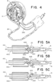
- FIG. 4 is an illustration of embolic coils (e.g., implant 12) being positioned within an aneurysm A, according to aspects of the present disclosure.
- the detachment system 10 is passed through a blood vessels BV to the aneurysm A through a catheter 250.
- the implant(s) 12 can loop and bend within the aneurysm sac to form a thrombotic mass.
- the implant(s) 12 can loop back on themselves and/or loop next to other implants. As the aneurysm A becomes increasingly packed, overlapping portions of the implant 12 can press into each other.
- FIGs. 5A-5C are illustrations of example loop wire 400 variations that increase friction at a pull wire 140.
- FIGs . 5A and 5B specifically show variations of twist 650 of the loop wire 400 at a distal end 144 of the pull wire 140.
- the loop wire 400 can extend through the lumen (e.g., lumen 108, 208, 308) of the tubular member on one side of the pull wire 140. After the loop wire passes the proximal end of the key 18 (e.g., the proximal extension 38), the loop wire 400 can cross over the pull wire 140 such and a distal end 404 of the loop wire 400 forms an opening 405 through which the pull wire 140 passes.
- the present detachment system 10 can include a twist 650 in the loop wire proximal to where the loop wire 400 crosses over the pull wire 400.
- the twist 650 causes the loop wire 400 to pass around the pull wire at least one time before terminating at the final, distal opening 405 of the pull wire 400.
- This twist 650 can be a singular twist, as shown in FIG. 5A , or the twist 650 can be a plurality of twists, as shown in FIG. 5B .
- the one or more twists 650 can increase the degree of tightness at the distal end 144 of the pull wire 140, thereby preventing unwanted proximal translation and resultant premature deployment of the implant 12.
- the distal end 144 of the pull wire 140 can be supported by the bridge 28 between the proximal opening 22 and the distal opening 24.
- the twist 650 in these examples, can be positioned proximal to the bridge 28, and the opening 405 in the loop wire 400 can be positioned within the proximal opening 22.
- the opening 405 of the loop wire 400 can be within the singular opening 26.
- example detachment systems 10 can include a friction coating 652 on the distal end 404 of the loop wire 400 proximate the opening 405 in the loop wire 400 through which the pull wire 140 extends.
- the friction coating 652 can include a silicone, rubber, synthetic polymer, or other coating to increase friction at the junction between the pull wire 140 and the loop wire 400.
- the distal end 404 of the loop wire 400 can have a roughened surface, for example by providing hatch marks and the like so as to increase the friction at the junction between the pull wire 140 and the loop wire 400.
- the distal end 144 of the pull wire 140 can also be configured to create additional friction.
- a low-friction polytetrafluoroethylene (PTFE) coating may be applied to the pull wire 140 to decrease friction to enable easier deployment of the implant 12.
- PTFE polytetrafluoroethylene
- easy deployment can, in some cases, cause inadvertent deployment of the implant.
- the distal end 144 of the pull wire 140 does not include a PTFE coating.
- the distal end 144 of the pull wire 140 can include a silicone, rubber, synthetic polymer, or other coating to increase friction at the junction between the pull wire 140 and the loop wire 400.
- the distal end 144 of the pull wire 140 can have a roughened surface, for example by providing hatch marks and the like so as to increase the friction at the junction between the pull wire 140 and the loop wire 400.
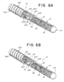
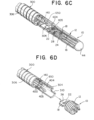
- FIGs. 6A-6D illustrate a sequence of steps for releasing an embolic implant 12 from a detachment system 10, according to aspects of the present disclosure.
- FIG. 6A is an illustration of the implant 12 and delivery tube (e.g., distal hypotube 300) configured for delivery and positioning of the implant 12.
- FIGs. 6B through 6D illustrate releasing the example embolic implant 12 from the distal hypotube 300. A portion of the distal hypotube 300 is cut away for illustration purposes. The more proximal features of the tubular body 90 are not shown in the views.
- FIG. 6A illustrates the detachment system including a pull wire 140 and a loop wire 400 locked into the key 18 of the implant 12 (the key shown in FIGs. 6A-6D is a dual opening key 18a, but the illustrations could equally apply to a single opening key 18b or a triple opening key 18c).
- the distal tube 300 can include a compressible portion 306.
- the loop wire 400 can have an opening 405 at a distal end 404 of the loop wire 400, and the opening 405 can be placed through an opening in the key 18 (e.g., proximal opening 22 in a dual opening key 18a, or the singular opening 26 in a single opening key 18b).
- the twist 650 can be twisted around the pull wire 140 proximal to the terminating end, i.e., the opening 405 through which the pull wire 140 extends.
- the implant 12 is now secure.
- the key can include a bridge 28 positioned distally from the loop wire opening 405 and positioned to support a distal portion of the pull wire 140 that is distal of where the loop wire opening 405 wraps around by the pull wire 140.
- the bridge 28 can support the distal portion of the pull wire 140 such that when the loop wire 400 tensions against the pull wire 140 at the loop opening 405, the bridge 28 can inhibit the distal portion of the pull wire 140 from deforming.
- the proximal tab 38 of the key 18 can be positioned to support a portion of the pull wire 140 that is proximal of where the loop wire opening 405 is supported by the pull wire 140.
- the combination of the bridge 28 and the proximal tab 38 can inhibit the pull wire 140 from deforming due to forces applied by the loop wire 400.
- the distal hypotube 300 can be detachably attached to the implant 12 as illustrated in FIG. 6A during delivery of the implant 12 through the vasculature and while the implant 12 is being positioned at a treatment site.
- the bridge 28 can reduce the likelihood that the implant 12 is prematurely released due to bending of the pull wire 140 due to forces from the loop wire 400.
- FIG. 6B illustrates the pull wire 140 being drawn proximally to begin the release sequence for the implant 12.
- FIG. 6C illustrates the instant the pull wire 140 exits the opening 405 and is pulled free of the loop wire 400.
- the distal end 404 of the loop wire 400 falls away and exits the key 18.
- FIG. 6D illustrates the end of the release sequence.
- the compressible portion 306 has expanded/returned to its original shape and "sprung” forward.
- An elastic force E is imparted by the distal end 304 of the distal hypotube 300 to the implant 12 to "push" it away to ensure a clean separation and delivery of the implant 12.
- the compressible portion 306 can be a spiral cut portion of the distal hypotube 300, for example a laser cut spiraled segment that can be compressed when the detachment system 10 is loaded.
- FIG. 7 is a flow diagram illustrating a method 800 for designing, constructing, or configuring a detachment system 10 and implant 12, according to aspects of the present disclosure.
- Steps 704 through 732 describe steps to create/construct one or more of detachment systems 10 described herein.
- the construction of the detachment system 10 can begin with providing a tubular body 90 comprising a lumen (e.g., lumen 108, 208, 308) extending therethrough and a compressible distal tube (e.g., distal hypotube 300).
- a loop wire 400 can be affixed to the tubular body 90.
- proximal ends of the loop wire can be attached to the tubular body at a first end attachment 406 and a second end attachment 408.
- the compressible distal tube 300 can be compressed into its loaded configuration.
- a loop wire opening 405 in the loop wire 400 can be positioned proximate a distal end 304 of the compressible distal tube such that the loop wire 400 is extended through the lumen (e.g., lumen 108, 208, 308).
- the pull wire 140 can be extended through the lumen (e.g., lumen 108, 208, 308).
- the loop opening 405 can be extended through a key 18 of an implantable medical device 12.
- the loop wire 400 can be twisted around the pull wire 140 at least one time, thereby creating the loop wire twist 650 described herein.
- a distal end 144 of the pull wire 140 can be extended through the twist 650 and loop opening 405 of the twisted loop wire 140.
- steps 736 and 740 provide additional steps to inhibit inadvertent proximal translation of the pull wire 140 and such that the implant can be deployed.
- steps 736 and 740 provide additional steps to inhibit inadvertent proximal translation of the pull wire 140 and such that the implant can be deployed.
- steps 736 and 740 provide additional steps to inhibit inadvertent proximal translation of the pull wire 140 and such that the implant can be deployed.
- proximal translation of the pull wire 140 through the loop wire 400 while the implantable medical device 12 is delivered through vasculature to a treatment site can be inhibited via frictional resistance of the twisted loop wire 400 around the pull wire 140.
- frictional resistance of the junction between the loop wire 400 and pull wire 140 can be overcome such that the pull wire 140 translates proximally and releases the implantable medical device 12 at the treatment site.
- the key 18 can be designed to provide additional friction at the pull wire 140 so as to further inhibit premature proximal translation of the pull wire 140.
- FIGs. 8A and 8B provide examples of such a construct, wherein the pull wire 140 can be weaved around one or more bridges of the key 18.
- FIG. 8A shows a "dual opening" key 18a, as shown and described above with reference to FIG. 2A .
- the key 18a can include a bridge 28 to separate the proximal opening 22 and the distal opening 24, as illustrated.
- the pull wire 140 can be weaved around the bridge 28 to create additional friction at the junction between the pull wire 140 and key 18a. For example and as shown in FIG.
- the pull wire 140 can pass over the proximal tab 38 of the key 18a at a first side of the key 18a, pass over/under the bridge 28 on a second side of the key 18a, weave back to the first side of the key 18a, and rest upon a distal end 40 of the key 18a on the first side of the key 18a.
- the pull wire 140 can have a stronger engagement with the key 18a so as to inhibit inadvertent proximal translation of the pull wire 140.
- the key 18 can include a plurality of bridges to enable more weaving of the pull wire 140 and thus provide additional friction.
- the key 18c e.g., a triple-opening key
- the first bridge 42 creates a first opening 46 between the proximal tab 38 and the first bridge 42.
- the second bridge 44 creates a second opening 48 between the first bridge 42 and the second bridge 44, as well as a third opening 50 between the second bridge 44 and the distal end 40 of the key 18c.
- the pull wire 140 can weave around the first bridge 42 and second bridge 44 through the first opening 46, the second opening 48, and the third opening 50.
- the pull wire 140 can pass over the proximal tab 38 of the key 18c at a first side of the key 18a, pass over/under the first bridge 42 on a second side of the key 18c, pass under/over the second bridge 44 on the first side of the key 18c, weave back to the second side of the key 18c, and rest upon a distal end 40 of the key 18c on the second side of the key 18c.
- the weaved pull wire 140 described with reference to FIGs. 8A and 8B can be used along with the twisting loop wires 400 described herein; it will also be understood that the weaved pull wire 140 described with reference to FIGs. 8A and 8B can be implemented as an alternative to the twisting loop wires 400 as a means to increase friction.
- the disclosure contemplates many variations and modifications of the implant and methods for making and using the same, wherein the methods for using the same do not form part of the present invention, including alternative materials, alternative geometries of component parts, alternative positioning of component parts in relation to each other, etc. These modifications would be apparent to those having ordinary skill in the art to which this disclosure relates. The scope of the invention is defined by the claims which follow.
Landscapes
- Health & Medical Sciences (AREA)
- Surgery (AREA)
- Life Sciences & Earth Sciences (AREA)
- Biomedical Technology (AREA)
- Medical Informatics (AREA)
- Veterinary Medicine (AREA)
- Public Health (AREA)
- Engineering & Computer Science (AREA)
- General Health & Medical Sciences (AREA)
- Heart & Thoracic Surgery (AREA)
- Nuclear Medicine, Radiotherapy & Molecular Imaging (AREA)
- Molecular Biology (AREA)
- Animal Behavior & Ethology (AREA)
- Reproductive Health (AREA)
- Vascular Medicine (AREA)
- Neurosurgery (AREA)
- Surgical Instruments (AREA)
Claims (13)
- Ablösesystem (10) zum Einbringen einer implantierbaren medizinischen Vorrichtung (12) an eine Zielstelle eines Körpergefäßes, das System umfassend:einen röhrenförmigen Körper (90), umfassend ein Lumen (108, 208, 308), das sich dahindurch erstreckt, und eine komprimierte distale Röhre (300);einen Schleifendraht (400), umfassend eine erste Endbefestigung (406) und eine zweite Endbefestigung (408), die an dem röhrenförmigen Körper angebracht sind, und ferner umfassend eine Schleifenöffnung (405), die in der Nähe eines distalen Endes (304) der komprimierten distalen Röhre positioniert ist; undeinen Zugdraht (140), der sich durch das Lumen und durch die Schleifenöffnung erstreckt, dadurch gekennzeichnet, dass der Schleifendraht eine Verdrehung (650) umfasst, derart, dass der Schleifendraht mindestens einmal um den Zugdraht gedreht ist, um eine Reibung zwischen dem Schleifendraht und dem Zugdraht zu erhöhen.
- Ablösesystem nach Anspruch 1, wobei ein distales Ende des Schleifendrahtes in der Nähe des Zugdrahtes eine Reibungsbeschichtung (652) umfasst.
- Ablösesystem nach Anspruch 1, wobei der Schleifendraht und der Zugdraht beweglich sind, um die implantierbare medizinische Vorrichtung von dem Ablösesystem freizugeben.
- Ablösesystem nach Anspruch 1, wobei die Drehung konfiguriert ist, um eine vorzeitige Ablösung der implantierbaren medizinischen Vorrichtung zu verhindern, durch Verhindern einer proximalen Translation des Zugdrahts aufgrund eines Reibungswiderstands, der durch den Schleifendraht über die Verdrehung bereitgestellt wird.
- Ablösesystem nach Anspruch 1, wobei der röhrenförmige Körper ferner eine flexible Spule umfasst, die in einer proximalen Richtung von der komprimierten distalen Röhre angeordnet ist, wobei der Schleifendraht eine Verlängerung der flexiblen Spule verhindert, wenn er über den Zugdraht geschlungen wird.
- Ablösesystem nach Anspruch 1, wobei der Schleifendraht eine Vielzahl von Malen um den Zugdraht verdreht ist.
- Ablösesystem nach Anspruch 6, wobei das Ablösesystem eine komprimierte distale Röhre umfasst, wobei der röhrenförmige Körper eine flexible Spule (200) umfasst, die in einer proximalen Richtung von der komprimierten distalen Röhre angeordnet ist, wobei der Schleifendraht die Verlängerung der flexiblen Spule verhindert, wenn er über den Zugdraht geschlungen wird.
- Ablösesystem nach Anspruch 1, ferner umfassend:einen Schlüssel (18), der konfiguriert ist, um an der implantierbaren medizinischen Vorrichtung in der Nähe eines proximalen Endes (15) der implantierbaren medizinischen Vorrichtung angebracht zu werden; undeine dehnungsfeste Faser (16), die mit dem Schlüssel in Eingriff steht, die konfiguriert ist, um sich durch ein Implantatlumen der implantierbaren medizinischen Vorrichtung zu erstrecken, und konfiguriert ist, um in der Nähe eines distalen Endes der implantierbaren medizinischen Vorrichtung an der implantierbaren medizinischen Vorrichtung angebracht zu werden.
- Ablösesystem nach Anspruch 8, wobei der Schlüssel umfasst:eine distale Öffnung (24) hindurch, wobei die dehnungsbeständige Faser durch die distale Öffnung verläuft;eine proximale Öffnung (22) hindurch; undeine Brücke (28), die die distale Öffnung und die proximale Öffnung trennt.
- Ablösesystem nach Anspruch 9, wobei die Brücke einen Abschnitt des Zugdrahtes in einer distalen Richtung von der Schleifenöffnung stützt.
- Ablösesystem nach Anspruch 10, wobei die Drehung in dem Schleifendraht proximal zu der Brücke positioniert ist.
- Ablösesystem nach Anspruch 9, sofern abhängig von Anspruch 1, wobei der Zugdraht derart über die Brücke gewebt ist, dass der Zugdraht von einer ersten Seite des Schlüssels durch die proximale Öffnung zu einer zweiten Seite des Schlüssels und über die Brücke und durch die distale Öffnung zu der ersten Seite des Schlüssels verläuft.
- Verfahren, umfassend:Bereitstellen eines röhrenförmigen Körpers (90), umfassend ein Lumen (108, 208, 308), das sich dahindurch erstreckt, und eine komprimierte distale Röhre (300);Anbringen eines Schleifendrahts (400) an dem röhrenförmigen Körper;Komprimieren der komprimierbaren distalen Röhre;Positionieren einer Schleifenöffnung (405) in dem Schleifendraht in der Nähe eines distalen Endes (304) der komprimierbaren distalen Röhre, derart, dass sich der Schleifendraht durch das Lumen erstreckt;Strecken eines Zugdrahtes (140) durch das Lumen;Strecken der Schleifenöffnung durch einen Schlüssel (18) einer implantierbaren medizinischen Vorrichtung (12);mindestens einmaliges Verdrehen des Schleifendrahtes um den Zugdraht; undStrecken eines distalen Endes (144) des Zugdrahtes durch die Schleifenöffnung des verdrehten Schleifendrahtes.
Applications Claiming Priority (1)
| Application Number | Priority Date | Filing Date | Title |
|---|---|---|---|
| US17/566,907 US12508032B2 (en) | 2021-12-31 | 2021-12-31 | Medical device delivery systems with twisting loop wires |
Publications (3)
| Publication Number | Publication Date |
|---|---|
| EP4205671A1 EP4205671A1 (de) | 2023-07-05 |
| EP4205671B1 true EP4205671B1 (de) | 2025-03-12 |
| EP4205671C0 EP4205671C0 (de) | 2025-03-12 |
Family
ID=84767133
Family Applications (1)
| Application Number | Title | Priority Date | Filing Date |
|---|---|---|---|
| EP22217254.6A Active EP4205671B1 (de) | 2021-12-31 | 2022-12-30 | Systeme zur einführung einer medizinischen vorrichtung mit twist-loop-drähten |
Country Status (6)
| Country | Link |
|---|---|
| US (1) | US12508032B2 (de) |
| EP (1) | EP4205671B1 (de) |
| JP (1) | JP2023099520A (de) |
| KR (1) | KR20230104008A (de) |
| CN (1) | CN116421248A (de) |
| ES (1) | ES3026574T3 (de) |
Family Cites Families (301)
| Publication number | Priority date | Publication date | Assignee | Title |
|---|---|---|---|---|
| US2220203A (en) | 1939-02-27 | 1940-11-05 | William L Branin | Cable clamp |
| US3429408A (en) | 1967-04-25 | 1969-02-25 | Associated Spring Corp | Actuator sleeves for spring clutch |
| US4858810A (en) | 1987-04-30 | 1989-08-22 | Heart Technology, Inc. | Quick acting pin vise for use with angiographic guidewires |
| US4985022A (en) | 1988-11-23 | 1991-01-15 | Med Institute, Inc. | Catheter having durable and flexible segments |
| US5484409A (en) | 1989-08-25 | 1996-01-16 | Scimed Life Systems, Inc. | Intravascular catheter and method for use thereof |
| US5122136A (en) | 1990-03-13 | 1992-06-16 | The Regents Of The University Of California | Endovascular electrolytically detachable guidewire tip for the electroformation of thrombus in arteries, veins, aneurysms, vascular malformations and arteriovenous fistulas |
| US5108407A (en) | 1990-06-08 | 1992-04-28 | Rush-Presbyterian St. Luke's Medical Center | Method and apparatus for placement of an embolic coil |
| US5234437A (en) | 1991-12-12 | 1993-08-10 | Target Therapeutics, Inc. | Detachable pusher-vasoocclusion coil assembly with threaded coupling |
| USD329698S (en) | 1991-12-13 | 1992-09-22 | Scimed Life Systems, Inc. | Clamp for gripping a guide wire or hollow tube for a catheter |
| US5636639A (en) | 1992-02-18 | 1997-06-10 | Symbiosis Corporation | Endoscopic multiple sample bioptome with enhanced biting action |
| SE9201295D0 (sv) | 1992-04-24 | 1992-04-24 | Siemens Elema Ab | Styrbar elektrodanordning |
| US5263964A (en) | 1992-05-06 | 1993-11-23 | Coil Partners Ltd. | Coaxial traction detachment apparatus and method |
| US5536248A (en) | 1992-05-11 | 1996-07-16 | Arrow Precision Products, Inc. | Method and apparatus for electrosurgically obtaining access to the biliary tree and placing a stent therein |
| US5250071A (en) | 1992-09-22 | 1993-10-05 | Target Therapeutics, Inc. | Detachable embolic coil assembly using interlocking clasps and method of use |
| US5350397A (en) | 1992-11-13 | 1994-09-27 | Target Therapeutics, Inc. | Axially detachable embolic coil assembly |
| US5382259A (en) | 1992-10-26 | 1995-01-17 | Target Therapeutics, Inc. | Vasoocclusion coil with attached tubular woven or braided fibrous covering |
| US5334210A (en) | 1993-04-09 | 1994-08-02 | Cook Incorporated | Vascular occlusion assembly |
| US5925059A (en) | 1993-04-19 | 1999-07-20 | Target Therapeutics, Inc. | Detachable embolic coil assembly |
| US5569221A (en) | 1994-07-07 | 1996-10-29 | Ep Technologies, Inc. | Catheter component bond and method |
| CA2203122A1 (en) | 1994-10-20 | 1996-05-02 | Mordechay Beyar | Cystoscope delivery system |
| US5645558A (en) | 1995-04-20 | 1997-07-08 | Medical University Of South Carolina | Anatomically shaped vasoocclusive device and method of making the same |
| US6273404B1 (en) | 1995-06-05 | 2001-08-14 | Scimed Life Systems, Inc. | Method of making monolithic hub and strain relief |
| US6168622B1 (en) | 1996-01-24 | 2001-01-02 | Microvena Corporation | Method and apparatus for occluding aneurysms |
| US5899935A (en) | 1997-08-04 | 1999-05-04 | Schneider (Usa) Inc. | Balloon expandable braided stent with restraint |
| US6203547B1 (en) | 1997-12-19 | 2001-03-20 | Target Therapeutics, Inc. | Vaso-occlusion apparatus having a manipulable mechanical detachment joint and a method for using the apparatus |
| US6113622A (en) | 1998-03-10 | 2000-09-05 | Cordis Corporation | Embolic coil hydraulic deployment system |
| US6835185B2 (en) | 1998-12-21 | 2004-12-28 | Micrus Corporation | Intravascular device deployment mechanism incorporating mechanical detachment |
| US6391037B1 (en) | 2000-03-02 | 2002-05-21 | Prodesco, Inc. | Bag for use in the intravascular treatment of saccular aneurysms |
| US6723108B1 (en) | 2000-09-18 | 2004-04-20 | Cordis Neurovascular, Inc | Foam matrix embolization device |
| US6623504B2 (en) | 2000-12-08 | 2003-09-23 | Scimed Life Systems, Inc. | Balloon catheter with radiopaque distal tip |
| WO2002054943A2 (en) | 2001-01-10 | 2002-07-18 | Cordis Neurovascular, Inc. | Embolic coil introducer system |
| US6537300B2 (en) | 2001-05-30 | 2003-03-25 | Scimed Life Systems, Inc. | Implantable obstruction device for septal defects |
| US6454780B1 (en) | 2001-06-21 | 2002-09-24 | Scimed Life Systems, Inc. | Aneurysm neck obstruction device |
| JP4257199B2 (ja) | 2001-07-05 | 2009-04-22 | プリシジョン バスキュラー システムズ,インコーポレイテッド | 捻転可能な軟先端医療装置 |
| US8715312B2 (en) | 2001-07-20 | 2014-05-06 | Microvention, Inc. | Aneurysm treatment device and method of use |
| US8252040B2 (en) | 2001-07-20 | 2012-08-28 | Microvention, Inc. | Aneurysm treatment device and method of use |
| US6811561B2 (en) | 2001-11-15 | 2004-11-02 | Cordis Neurovascular, Inc. | Small diameter deployment system with improved headpiece |
| AU2002353016A1 (en) | 2001-12-03 | 2003-06-17 | Ekos Corporation | Small vessel ultrasound catheter |
| JP4328209B2 (ja) | 2002-01-25 | 2009-09-09 | アトリテック, インコーポレイテッド | 心耳血液ろ過システム |
| US20030195553A1 (en) | 2002-04-12 | 2003-10-16 | Scimed Life Systems, Inc. | System and method for retaining vaso-occlusive devices within an aneurysm |
| US7608058B2 (en) | 2002-07-23 | 2009-10-27 | Micrus Corporation | Stretch resistant therapeutic device |
| US8425549B2 (en) | 2002-07-23 | 2013-04-23 | Reverse Medical Corporation | Systems and methods for removing obstructive matter from body lumens and treating vascular defects |
| US7208003B2 (en) | 2002-09-20 | 2007-04-24 | Cordis Neurovascular, Inc. | Reattachable introducer for a medical device deployment system |
| FR2853521B1 (fr) | 2003-04-10 | 2005-12-02 | Claude Mialhe | Dispositif de dilatation d'un vaisseau et introducteur d'implant vasculaire |
| US7371228B2 (en) | 2003-09-19 | 2008-05-13 | Medtronic Vascular, Inc. | Delivery of therapeutics to treat aneurysms |
| US8182544B2 (en) | 2003-10-08 | 2012-05-22 | Codman & Shurtleff, Inc. | Method for placing a medical agent into a vessel of the body |
| US9308382B2 (en) | 2004-06-10 | 2016-04-12 | Medtronic Urinary Solutions, Inc. | Implantable pulse generator systems and methods for providing functional and/or therapeutic stimulation of muscles and/or nerves and/or central nervous system tissue |
| US20060025801A1 (en) | 2004-07-30 | 2006-02-02 | Robert Lulo | Embolic device deployment system with filament release |
| US9655633B2 (en) | 2004-09-10 | 2017-05-23 | Penumbra, Inc. | System and method for treating ischemic stroke |
| CA2581272A1 (en) | 2004-09-22 | 2006-05-18 | Lee R. Guterman | Cranial aneurysm treatment arrangement |
| US20060089637A1 (en) | 2004-10-14 | 2006-04-27 | Werneth Randell L | Ablation catheter |
| DE602004010276D1 (de) | 2004-11-10 | 2008-01-03 | Creganna Technologies Ltd | Einführkatheteranordnung für stents |
| US8562672B2 (en) | 2004-11-19 | 2013-10-22 | Medtronic, Inc. | Apparatus for treatment of cardiac valves and method of its manufacture |
| US20060116714A1 (en) | 2004-11-26 | 2006-06-01 | Ivan Sepetka | Coupling and release devices and methods for their assembly and use |
| US8425550B2 (en) | 2004-12-01 | 2013-04-23 | Boston Scientific Scimed, Inc. | Embolic coils |
| US7608089B2 (en) | 2004-12-22 | 2009-10-27 | Boston Scientific Scimed, Inc. | Vaso-occlusive device having pivotable coupling |
| US20060206139A1 (en) | 2005-01-19 | 2006-09-14 | Tekulve Kurt J | Vascular occlusion device |
| EP3266414B1 (de) | 2005-05-12 | 2024-07-17 | Covidien LP | Implantatfreisetzungssystem mit verzahnter rx-port-ausrichtung |
| US7377932B2 (en) | 2005-06-02 | 2008-05-27 | Cordis Neurovascular, Inc. | Embolic coil delivery system with mechanical release mechanism |
| US20060276833A1 (en) | 2005-06-02 | 2006-12-07 | Keith Balgobin | Stretch resistant embolic coil delivery system with spring assisted release mechanism |
| US7819891B2 (en) | 2005-06-02 | 2010-10-26 | Codman & Shurtleff, Inc. | Stretch resistant embolic coil delivery system with spring release mechanism |
| US20060276827A1 (en) | 2005-06-02 | 2006-12-07 | Vladimir Mitelberg | Stretch resistant embolic coil delivery system with mechanical release mechanism |
| US20060276825A1 (en) | 2005-06-02 | 2006-12-07 | Vladimir Mitelberg | Stretch resistant embolic coil delivery system with mechanical release mechanism |
| US7708755B2 (en) | 2005-06-02 | 2010-05-04 | Codman & Shurtleff Inc. | Stretch resistant embolic coil delivery system with combined mechanical and pressure release mechanism |
| US7371252B2 (en) | 2005-06-02 | 2008-05-13 | Cordis Neurovascular, Inc. | Stretch resistant embolic coil delivery system with mechanical release mechanism |
| US7811305B2 (en) | 2005-06-02 | 2010-10-12 | Codman & Shurtleff, Inc. | Stretch resistant embolic coil delivery system with spring release mechanism |
| US20060276830A1 (en) | 2005-06-02 | 2006-12-07 | Keith Balgobin | Stretch resistant embolic coil delivery system with mechanical release mechanism |
| US7708754B2 (en) | 2005-06-02 | 2010-05-04 | Codman & Shurtleff, Pc | Stretch resistant embolic coil delivery system with mechanical release mechanism |
| US7819892B2 (en) | 2005-06-02 | 2010-10-26 | Codman & Shurtleff, Inc. | Embolic coil delivery system with spring wire release mechanism |
| US7985238B2 (en) | 2005-06-02 | 2011-07-26 | Codman & Shurtleff, Inc. | Embolic coil delivery system with spring wire release mechanism |
| US7799052B2 (en) | 2005-06-02 | 2010-09-21 | Codman & Shurtleff, Inc. | Stretch resistant embolic coil delivery system with mechanical release mechanism |
| US7371251B2 (en) | 2005-06-02 | 2008-05-13 | Cordis Neurovascular, Inc. | Stretch resistant embolic coil delivery system with mechanical release mechanism |
| US7367987B2 (en) | 2005-06-02 | 2008-05-06 | Cordis Neurovascular, Inc. | Stretch resistant embolic coil delivery system with mechanical release mechanism |
| US9636115B2 (en) | 2005-06-14 | 2017-05-02 | Stryker Corporation | Vaso-occlusive delivery device with kink resistant, flexible distal end |
| EP1895927A4 (de) | 2005-06-20 | 2011-03-09 | Medtronic Ablation Frontiers | Ablationskatheter |
| JP4627687B2 (ja) | 2005-06-20 | 2011-02-09 | Junken Medical株式会社 | ステントの挿入装置 |
| US20070083132A1 (en) | 2005-10-11 | 2007-04-12 | Sharrow James S | Medical device coil |
| US8066036B2 (en) | 2005-11-17 | 2011-11-29 | Microvention, Inc. | Three-dimensional complex coil |
| US9307996B2 (en) | 2005-12-13 | 2016-04-12 | DePuy Synthes Products, Inc. | Detachment actuator for use with medical device deployment systems |
| WO2007070793A2 (en) | 2005-12-13 | 2007-06-21 | Cordis Development Corporation | Two-pitch threaded handle detachment system |
| US7344558B2 (en) | 2006-02-28 | 2008-03-18 | Cordis Development Corporation | Embolic device delivery system |
| US9757260B2 (en) | 2006-03-30 | 2017-09-12 | Medtronic Vascular, Inc. | Prosthesis with guide lumen |
| US7766933B2 (en) | 2006-03-31 | 2010-08-03 | Codman & Shurtleff, Inc. | Stretch resistant design for embolic coils with stabilization bead |
| US9615832B2 (en) | 2006-04-07 | 2017-04-11 | Penumbra, Inc. | Aneurysm occlusion system and method |
| CA2649702C (en) | 2006-04-17 | 2014-12-09 | Microtherapeutics, Inc. | System and method for mechanically positioning intravascular implants |
| US8777979B2 (en) | 2006-04-17 | 2014-07-15 | Covidien Lp | System and method for mechanically positioning intravascular implants |
| CA2655026C (en) | 2006-06-15 | 2016-08-02 | Microvention, Inc. | Embolization device constructed from expansible polymer |
| US8366720B2 (en) | 2006-07-31 | 2013-02-05 | Codman & Shurtleff, Inc. | Interventional medical device system having an elongation retarding portion and method of using the same |
| US8062325B2 (en) | 2006-07-31 | 2011-11-22 | Codman & Shurtleff, Inc. | Implantable medical device detachment system and methods of using the same |
| US7901444B2 (en) | 2006-09-29 | 2011-03-08 | Codman & Shurtleff, Inc. | Embolic coil delivery system with mechanical release mechanism |
| US20080306503A1 (en) | 2006-11-20 | 2008-12-11 | Boston Scientific Scimed, Inc. | Mechanically detachable vaso-occlusive device |
| WO2008085606A1 (en) | 2006-11-20 | 2008-07-17 | Boston Scientific Scimed, Inc. | Mechanically detachable vaso-occlusive device |
| WO2008064209A1 (en) * | 2006-11-20 | 2008-05-29 | Boston Scientific Scimed, Inc. | Mechanically detachable vaso-occlusive device |
| WO2008074027A1 (en) | 2006-12-13 | 2008-06-19 | Biomerix Corporation | Aneurysm occlusion devices |
| US8795316B2 (en) | 2007-04-25 | 2014-08-05 | DePuy Syntheses Products, LLC | Implantable medical device delivery system with a frangible portion and methods of making and using the same |
| US8864789B2 (en) | 2007-04-27 | 2014-10-21 | DePuy Synthes Products, LLC | Interventional medical device system having a spiral section and radiopaque marker and method of making the same |
| US8197442B2 (en) | 2007-04-27 | 2012-06-12 | Codman & Shurtleff, Inc. | Interventional medical device system having a slotted section and radiopaque marker and method of making the same |
| AU2008254770A1 (en) | 2007-05-18 | 2008-11-27 | Stryker Corporation | Medical implant detachment systems |
| DE102007038446A1 (de) | 2007-08-14 | 2009-02-19 | pfm Produkte für die Medizin AG | Embolisiereinrichtung |
| US20090099592A1 (en) | 2007-10-15 | 2009-04-16 | Boston Scientific Scimed, Inc. | Detachable Interlock Systems and Methods of Use |
| WO2009086208A2 (en) | 2007-12-21 | 2009-07-09 | Microvention, Inc. | Hydrogel filaments for biomedical uses |
| US8974518B2 (en) | 2008-03-25 | 2015-03-10 | Medtronic Vascular, Inc. | Eversible branch stent-graft and deployment method |
| EP2387959B1 (de) | 2008-04-21 | 2013-11-13 | Covidien LP | Kugelgeflecht-Embolievorrichtung und -Ausgabesysteme |
| WO2009135075A1 (en) | 2008-04-30 | 2009-11-05 | Medtronic, Inc. | Techniques for placing medical leads for electrical stimulation of nerve tissue |
| US20090312748A1 (en) | 2008-06-11 | 2009-12-17 | Johnson Kirk L | Rotational detachment mechanism |
| US8070694B2 (en) | 2008-07-14 | 2011-12-06 | Medtronic Vascular, Inc. | Fiber based medical devices and aspiration catheters |
| US8333796B2 (en) | 2008-07-15 | 2012-12-18 | Penumbra, Inc. | Embolic coil implant system and implantation method |
| US9232992B2 (en) | 2008-07-24 | 2016-01-12 | Aga Medical Corporation | Multi-layered medical device for treating a target site and associated method |
| US8721714B2 (en) | 2008-09-17 | 2014-05-13 | Medtronic Corevalve Llc | Delivery system for deployment of medical devices |
| AU2009303677B2 (en) | 2008-10-13 | 2014-04-24 | Stryker European Holdings I, Llc | Vaso-occlusive coil delivery system |
| US8758847B2 (en) | 2009-02-18 | 2014-06-24 | AUST Development, LLC | Apparatus and methods for making coated liners and tubular devices including such liners |
| JP5608731B2 (ja) * | 2009-04-15 | 2014-10-15 | マイクロベンション インコーポレイテッド | インプラント送達システム |
| US8974488B2 (en) | 2009-04-20 | 2015-03-10 | Achieva Medical Limited | Delivery assembly for occlusion device using mechanical interlocking coupling mechanism |
| US8758423B2 (en) | 2009-06-18 | 2014-06-24 | Graftcraft I Goteborg Ab | Device and method for treating ruptured aneurysms |
| JPWO2011030820A1 (ja) | 2009-09-09 | 2013-02-07 | 株式会社カネカ | 塞栓コイル |
| US9956100B2 (en) | 2009-09-15 | 2018-05-01 | Brightwater Medical, Inc. | Systems and methods for coupling and decoupling a catheter |
| WO2011038017A1 (en) | 2009-09-22 | 2011-03-31 | Penumbra, Inc. | Manual actuation system for deployment of implant |
| KR20110043799A (ko) | 2009-10-16 | 2011-04-28 | 강호창 | 마이크로코일 어셈블리 |
| EP2498691B1 (de) | 2009-11-09 | 2015-01-07 | Covidien LP | Eigenschaften einer kugelgeflecht-embolievorrichtung |
| US20110118772A1 (en) | 2009-11-13 | 2011-05-19 | Boston Scientific Scimed, Inc. | Delivery wire assembly for occlusive device delivery system |
| US20110118776A1 (en) | 2009-11-18 | 2011-05-19 | Boston Scientific Scimed, Inc. | Delivery wire assembly for occlusive device delivery system |
| CN102188300B (zh) | 2010-03-02 | 2014-05-28 | 上海微创医疗器械(集团)有限公司 | 一种动脉瘤手术装置 |
| CA2795740C (en) | 2010-04-14 | 2018-03-13 | Microvention, Inc. | Implant delivery device |
| US8764811B2 (en) | 2010-04-20 | 2014-07-01 | Medtronic Vascular, Inc. | Controlled tip release stent graft delivery system and method |
| US8876878B2 (en) | 2010-07-23 | 2014-11-04 | Medtronic, Inc. | Attachment mechanism for stent release |
| US8616040B2 (en) | 2010-09-17 | 2013-12-31 | Medtronic Vascular, Inc. | Method of forming a drug-eluting medical device |
| US9039749B2 (en) | 2010-10-01 | 2015-05-26 | Covidien Lp | Methods and apparatuses for flow restoration and implanting members in the human body |
| WO2012088162A1 (en) | 2010-12-20 | 2012-06-28 | Microvention, Inc. | Polymer stents and methods of manufacture |
| WO2012092351A2 (en) * | 2010-12-30 | 2012-07-05 | Cook Medical Technologies Llc | Delivery of an embolization coil with an attacher |
| US20120283768A1 (en) | 2011-05-05 | 2012-11-08 | Sequent Medical Inc. | Method and apparatus for the treatment of large and giant vascular defects |
| US9486604B2 (en) | 2011-05-12 | 2016-11-08 | Medtronic, Inc. | Packaging and preparation tray for a delivery system |
| US8795241B2 (en) | 2011-05-13 | 2014-08-05 | Spiration, Inc. | Deployment catheter |
| JP6026513B2 (ja) | 2011-05-13 | 2016-11-16 | スパイレーション インコーポレイテッド ディー ビー エイ オリンパス レスピラトリー アメリカ | 展開カテーテル |
| WO2012158668A1 (en) | 2011-05-17 | 2012-11-22 | Stryker Corporation | Method of fabricating an implantable medical device that includes one or more thin film polymer support layers |
| WO2012166467A1 (en) | 2011-05-27 | 2012-12-06 | Stryker Corporation | Assembly for percutaneously inserting an implantable medical device, steering the device to a target location and deploying the device |
| US9750565B2 (en) | 2011-09-30 | 2017-09-05 | Medtronic Advanced Energy Llc | Electrosurgical balloons |
| KR101315443B1 (ko) | 2011-12-02 | 2013-10-07 | 강호창 | 마이크로코일 어셈블리 |
| CA2867181C (en) | 2012-03-16 | 2020-08-11 | Microvention, Inc. | Stent and stent delivery device |
| US9717421B2 (en) | 2012-03-26 | 2017-08-01 | Medtronic, Inc. | Implantable medical device delivery catheter with tether |
| US9220906B2 (en) | 2012-03-26 | 2015-12-29 | Medtronic, Inc. | Tethered implantable medical device deployment |
| US9833625B2 (en) | 2012-03-26 | 2017-12-05 | Medtronic, Inc. | Implantable medical device delivery with inner and outer sheaths |
| US9155540B2 (en) | 2012-03-30 | 2015-10-13 | DePuy Synthes Products, Inc. | Embolic coil detachment mechanism with heating element and kicker |
| US8920459B2 (en) | 2012-03-30 | 2014-12-30 | DePuy Synthes Products, LLC | Embolic coil detachment mechanism with flexible distal member and resistive electrical heating element |
| US9242290B2 (en) | 2012-04-03 | 2016-01-26 | Medtronic Vascular, Inc. | Method and apparatus for creating formed elements used to make wound stents |
| US9700399B2 (en) | 2012-04-26 | 2017-07-11 | Medtronic Vascular, Inc. | Stopper to prevent graft material slippage in a closed web stent-graft |
| US9549832B2 (en) | 2012-04-26 | 2017-01-24 | Medtronic Vascular, Inc. | Apparatus and methods for filling a drug eluting medical device via capillary action |
| GB2501714B (en) | 2012-05-02 | 2014-05-07 | Cook Medical Technologies Llc | Implant delivery system |
| EP2668915A1 (de) | 2012-06-01 | 2013-12-04 | Acandis GmbH & Co. KG | System zur Bereitstellung einer dehnfesten, gefäßverschließenden Vorrichtung und Herstellungsverfahren dafür |
| US9370448B2 (en) | 2012-06-15 | 2016-06-21 | Preceptis Medical, Inc. | Insertion system for deploying a ventilation device |
| US10124087B2 (en) | 2012-06-19 | 2018-11-13 | Covidien Lp | Detachable coupling for catheter |
| US9149190B2 (en) | 2012-07-17 | 2015-10-06 | Stryker Corporation | Notification system of deviation from predefined conditions |
| US9770251B2 (en) | 2012-08-13 | 2017-09-26 | Microvention, Inc. | Shaped removal device |
| US20140058435A1 (en) | 2012-08-21 | 2014-02-27 | Donald K. Jones | Implant delivery and release system |
| US9504476B2 (en) | 2012-10-01 | 2016-11-29 | Microvention, Inc. | Catheter markers |
| BR112015008245B1 (pt) | 2012-10-15 | 2022-09-27 | Microvention, Inc | Composições poliméricas de tratamento |
| US20140135811A1 (en) | 2012-11-13 | 2014-05-15 | Covidien Lp | Occlusive devices |
| US9539022B2 (en) | 2012-11-28 | 2017-01-10 | Microvention, Inc. | Matter conveyance system |
| WO2014089392A1 (en) | 2012-12-07 | 2014-06-12 | Medtronic, Inc. | Minimally invasive implantable neurostimulation system |
| EP2941296B1 (de) | 2013-01-03 | 2019-05-15 | Donald K. Jones | Lösbares spulenlösesystem und griffanordnung |
| US10342546B2 (en) | 2013-01-14 | 2019-07-09 | Microvention, Inc. | Occlusive device |
| GB2509952B (en) | 2013-01-18 | 2015-01-28 | Cook Medical Technologies Llc | Medical device loading and carrier tool |
| US9949739B2 (en) | 2013-02-27 | 2018-04-24 | Microvention, Inc. | Integral wiping system and method |
| US9539382B2 (en) | 2013-03-12 | 2017-01-10 | Medtronic, Inc. | Stepped catheters with flow restrictors and infusion systems using the same |
| US9149278B2 (en) | 2013-03-13 | 2015-10-06 | DePuy Synthes Products, Inc. | Occlusive device delivery system with mechanical detachment |
| US9539011B2 (en) | 2013-03-14 | 2017-01-10 | Stryker Corporation | Vaso-occlusive device delivery system |
| WO2014158790A2 (en) | 2013-03-14 | 2014-10-02 | Incumedx Inc. | Implants, methods of manufacturing the same, and devices and methods for delivering the implants to a vascular disorder of a patient |
| EP3009084B1 (de) | 2013-03-14 | 2017-09-13 | Stryker Corporation | Freisetzungssystem für vasookklusive vorrichtung |
| EP2967572B1 (de) | 2013-03-14 | 2019-04-24 | Stryker Corporation | Freisetzungssystem für vasookklusive vorrichtung |
| US9833252B2 (en) | 2013-03-15 | 2017-12-05 | Microvention, Inc. | Multi-component obstruction removal system and method |
| WO2014145012A2 (en) | 2013-03-15 | 2014-09-18 | Covidien Lp | Delivery and detachment mechanisms for vascular implants |
| US9398966B2 (en) | 2013-03-15 | 2016-07-26 | Medtronic Vascular, Inc. | Welded stent and stent delivery system |
| JP6636908B2 (ja) | 2013-03-15 | 2020-01-29 | テルモ株式会社 | 塞栓防止装置 |
| CN108433769B (zh) | 2013-03-15 | 2021-06-08 | 柯惠有限合伙公司 | 闭塞装置 |
| WO2014174437A1 (en) | 2013-04-22 | 2014-10-30 | Sandvik Intellectual Property Ab | Method for drug loading hydroxyapatite coated implant surfaces |
| US9445928B2 (en) | 2013-05-30 | 2016-09-20 | Medtronic Vascular, Inc. | Delivery system having a single handed deployment handle for a retractable outer sheath |
| US11291452B2 (en) | 2013-06-26 | 2022-04-05 | W. L. Gore & Associates, Inc. | Medical device deployment system |
| US10953193B2 (en) | 2013-07-16 | 2021-03-23 | Covidien Lp | Microcatheter with modified PTFE liner |
| US9662120B2 (en) | 2013-08-23 | 2017-05-30 | Cook Medical Technologies Llc | Detachable treatment device delivery system utilizing compression at attachment zone |
| US9782186B2 (en) | 2013-08-27 | 2017-10-10 | Covidien Lp | Vascular intervention system |
| US9675782B2 (en) | 2013-10-10 | 2017-06-13 | Medtronic Vascular, Inc. | Catheter pull wire actuation mechanism |
| US9955978B2 (en) | 2013-10-25 | 2018-05-01 | Medtronic Vascular, Inc. | Tissue compression device with multi-chamber bladder |
| WO2015066549A1 (en) | 2013-10-31 | 2015-05-07 | Sentreheart, Inc. | Devices and methods for left atrial appendage closure |
| CA2934555C (en) | 2013-12-20 | 2020-07-07 | Microvention, Inc. | Device delivery system |
| US9833604B2 (en) | 2013-12-20 | 2017-12-05 | Microvention, Inc. | Delivery adapter |
| US9566072B2 (en) | 2013-12-27 | 2017-02-14 | Blockade Medical, LLC | Coil system |
| US9788839B2 (en) | 2014-02-14 | 2017-10-17 | Cook Medical Technologies Llc | Stable screw-type detachment mechanism |
| EP3128962B1 (de) | 2014-04-08 | 2018-05-23 | Stryker Corporation | System zur freisetzung von implantaten |
| US9629635B2 (en) | 2014-04-14 | 2017-04-25 | Sequent Medical, Inc. | Devices for therapeutic vascular procedures |
| WO2015167997A1 (en) | 2014-04-30 | 2015-11-05 | Stryker Corporation | Implant delivery system and method of use |
| US9060777B1 (en) | 2014-05-28 | 2015-06-23 | Tw Medical Technologies, Llc | Vaso-occlusive devices and methods of use |
| US9668898B2 (en) | 2014-07-24 | 2017-06-06 | Medtronic Vascular, Inc. | Stent delivery system having dynamic deployment and methods of manufacturing same |
| CN106659505B (zh) | 2014-07-25 | 2019-07-02 | 因库麦迪斯有限公司 | 具有遮蔽物的栓塞线圈 |
| US9918718B2 (en) | 2014-08-08 | 2018-03-20 | DePuy Synthes Products, Inc. | Embolic coil delivery system with retractable mechanical release mechanism |
| EP3936088A1 (de) | 2014-08-12 | 2022-01-12 | Merit Medical Systems, Inc. | Systeme und verfahren zur kopplung und entkopplung eines katheters |
| US9770577B2 (en) | 2014-09-15 | 2017-09-26 | Medtronic Xomed, Inc. | Pressure relief for a catheter balloon device |
| KR20170056666A (ko) | 2014-09-17 | 2017-05-23 | 메타랙티브 메디컬, 인크. | 팽창 가능한 바디 디바이스 및 이용 방법 |
| US9579484B2 (en) | 2014-09-19 | 2017-02-28 | Medtronic Vascular, Inc. | Sterile molded dispenser |
| GB2533087B (en) | 2014-12-08 | 2018-08-08 | Cook Medical Technologies Llc | Medical implant detachment mechanism and introducer assembly |
| US11484319B2 (en) | 2015-01-20 | 2022-11-01 | Neurogami Medical, Inc. | Delivery system for micrograft for treating intracranial aneurysms |
| US10857012B2 (en) | 2015-01-20 | 2020-12-08 | Neurogami Medical, Inc. | Vascular implant |
| US10925611B2 (en) | 2015-01-20 | 2021-02-23 | Neurogami Medical, Inc. | Packaging for surgical implant |
| JP6763864B2 (ja) | 2015-01-20 | 2020-09-30 | ニューロガミ メディカル インコーポレイテッド | 頭蓋内動脈瘤の治療のためのマイクログラフトおよび使用方法 |
| US9692557B2 (en) | 2015-02-04 | 2017-06-27 | Stryker European Holdings I, Llc | Apparatus and methods for administering treatment within a bodily duct of a patient |
| US10888331B2 (en) | 2015-02-10 | 2021-01-12 | Boston Scientific Scimed, Inc. | Active release of embolic coils |
| WO2016140313A1 (ja) | 2015-03-03 | 2016-09-09 | 株式会社カネカメディックス | 血管塞栓用具、およびその製造方法 |
| US9375333B1 (en) | 2015-03-06 | 2016-06-28 | Covidien Lp | Implantable device detachment systems and associated devices and methods |
| EP3253304B1 (de) | 2015-03-26 | 2020-07-08 | Boston Scientific Scimed, Inc. | System zur einführung einer emboliespirale mit leicht lösbarem knoten |
| EP3291773B1 (de) | 2015-05-07 | 2026-01-07 | The Medical Research, Infrastructure, And Health Services Fund Of The Tel Aviv Medical Center | Temporäre interatriale shunts |
| US9717503B2 (en) | 2015-05-11 | 2017-08-01 | Covidien Lp | Electrolytic detachment for implant delivery systems |
| US10398874B2 (en) | 2015-05-29 | 2019-09-03 | Covidien Lp | Catheter distal tip configuration |
| US10154905B2 (en) | 2015-08-07 | 2018-12-18 | Medtronic Vascular, Inc. | System and method for deflecting a delivery catheter |
| US10307168B2 (en) | 2015-08-07 | 2019-06-04 | Terumo Corporation | Complex coil and manufacturing techniques |
| EP3334354B1 (de) | 2015-08-11 | 2021-03-03 | Terumo Corporation | System zur implantatfreisetzung |
| US20170072165A1 (en) | 2015-09-11 | 2017-03-16 | Cathera, Inc. | Catheter shaft and associated devices, systems, and methods |
| US20200147347A1 (en) | 2015-09-15 | 2020-05-14 | Orbusneich Medical Pte. Ltd. | Vascular re-entry catheter |
| EP3349689B1 (de) | 2015-09-18 | 2023-12-27 | Microvention, Inc. | Implantatretentions-, -ablöse- und -einführungssystem |
| CN108156803B (zh) | 2015-09-18 | 2021-05-04 | 泰尔茂株式会社 | 可推动的植入物传送系统 |
| JP6816127B2 (ja) | 2015-09-18 | 2021-01-20 | テルモ株式会社 | 血管プロテーゼ |
| JP6816126B2 (ja) | 2015-09-18 | 2021-01-20 | マイクロベンション インコーポレイテッドMicrovention, Inc. | 解放可能な送達システム |
| ES2788738T3 (es) | 2015-09-21 | 2020-10-22 | Stryker Corp | Dispositivos de embolectomía |
| CN108024821B (zh) | 2015-09-21 | 2020-10-30 | 斯瑞克公司 | 栓子切除设备 |
| US10172632B2 (en) | 2015-09-22 | 2019-01-08 | Medtronic Vascular, Inc. | Occlusion bypassing apparatus with a re-entry needle and a stabilization tube |
| WO2017062572A1 (en) | 2015-10-06 | 2017-04-13 | Boston Scientific Scimed, Inc. | Pusher arm and ball release mechanism for embolic coils |
| US10327791B2 (en) | 2015-10-07 | 2019-06-25 | Medtronic Vascular, Inc. | Occlusion bypassing apparatus with a re-entry needle and a distal stabilization balloon |
| WO2017062383A1 (en) | 2015-10-07 | 2017-04-13 | Stryker Corporation | Multiple barrel clot removal devices |
| US10786302B2 (en) | 2015-10-09 | 2020-09-29 | Medtronic, Inc. | Method for closure and ablation of atrial appendage |
| US20190021737A1 (en) | 2015-10-14 | 2019-01-24 | Three Rivers Medical Inc. | Mechanical embolization delivery apparatus and methods |
| US10271873B2 (en) | 2015-10-26 | 2019-04-30 | Medtronic Vascular, Inc. | Sheathless guide catheter assembly |
| US11090055B2 (en) | 2015-10-30 | 2021-08-17 | Incumedx Inc. | Devices and methods for delivering an implant to a vascular disorder |
| US20170147765A1 (en) | 2015-11-19 | 2017-05-25 | Penumbra, Inc. | Systems and methods for treatment of stroke |
| US10631946B2 (en) | 2015-11-30 | 2020-04-28 | Penumbra, Inc. | System for endoscopic intracranial procedures |
| WO2017100472A1 (en) | 2015-12-09 | 2017-06-15 | Medtronic Vascular Inc. | Catheter with a lumen shaped as an identification symbol |
| US10159568B2 (en) | 2015-12-14 | 2018-12-25 | Medtronic, Inc. | Delivery system having retractable wires as a coupling mechanism and a deployment mechanism for a self-expanding prosthesis |
| US10500046B2 (en) | 2015-12-14 | 2019-12-10 | Medtronic, Inc. | Delivery system having retractable wires as a coupling mechanism and a deployment mechanism for a self-expanding prosthesis |
| US10743883B2 (en) | 2015-12-30 | 2020-08-18 | Stryker European Holdings I, Llc | Embolic devices and methods of manufacturing same |
| US20170189033A1 (en) | 2016-01-06 | 2017-07-06 | Microvention, Inc. | Occlusive Embolic Coil |
| US10070950B2 (en) | 2016-02-09 | 2018-09-11 | Medtronic Vascular, Inc. | Endoluminal prosthetic assemblies, and associated systems and methods for percutaneous repair of a vascular tissue defect |
| AU2017217879B9 (en) | 2016-02-10 | 2021-08-19 | Microvention, Inc. | Intravascular treatment site access |
| AU2017218115B2 (en) | 2016-02-10 | 2020-03-05 | Microvention, Inc. | Devices for vascular occlusion |
| US10188500B2 (en) | 2016-02-12 | 2019-01-29 | Medtronic Vascular, Inc. | Stent graft with external scaffolding and method |
| US10485579B2 (en) | 2016-02-25 | 2019-11-26 | Indian Wells Medical, Inc. | Steerable endoluminal punch |
| US20170258476A1 (en) | 2016-03-08 | 2017-09-14 | Terumo Kabushiki Kaisha | Blood vessel treatment method |
| US20170281331A1 (en) | 2016-03-31 | 2017-10-05 | Medtronic Vascular, Inc. | Endoluminal prosthetic devices having fluid-absorbable compositions for repair of a vascular tissue defect |
| EP4112111A1 (de) | 2016-03-31 | 2023-01-04 | Medtronic Vascular Inc. | Expandierbare einführhülse |
| US10695542B2 (en) | 2016-04-04 | 2020-06-30 | Medtronic Vascular, Inc. | Drug coated balloon |
| US10252024B2 (en) | 2016-04-05 | 2019-04-09 | Stryker Corporation | Medical devices and methods of manufacturing same |
| US10441407B2 (en) | 2016-04-12 | 2019-10-15 | Medtronic Vascular, Inc. | Gutter filling stent-graft and method |
| US9987122B2 (en) | 2016-04-13 | 2018-06-05 | Medtronic Vascular, Inc. | Iliac branch device and method |
| US10010403B2 (en) | 2016-04-18 | 2018-07-03 | Medtronic Vascular, Inc. | Stent-graft prosthesis and method of manufacture |
| US20170304097A1 (en) | 2016-04-21 | 2017-10-26 | Medtronic Vascular, Inc. | Stent-graft delivery system having an inner shaft component with a loading pad or covering on a distal segment thereof for stent retention |
| ES2859656T3 (es) | 2016-04-25 | 2021-10-04 | Stryker Corp | Aparatos de trombectomía antiatascamiento y macerante |
| US10940294B2 (en) | 2016-04-25 | 2021-03-09 | Medtronic Vascular, Inc. | Balloon catheter including a drug delivery sheath |
| US10517711B2 (en) | 2016-04-25 | 2019-12-31 | Medtronic Vascular, Inc. | Dissection prosthesis system and method |
| JP6934935B2 (ja) | 2016-04-25 | 2021-09-15 | ストライカー コーポレイションStryker Corporation | 反転式機械的血栓除去装置、および血管内の使用方法 |
| JP6924256B2 (ja) | 2016-04-25 | 2021-08-25 | ストライカー コーポレイションStryker Corporation | 予め組み込まれた反転トラクタの血栓除去装置および方法 |
| US11147952B2 (en) | 2016-04-28 | 2021-10-19 | Medtronic Vascular, Inc. | Drug coated inflatable balloon having a thermal dependent release layer |
| US10406011B2 (en) | 2016-04-28 | 2019-09-10 | Medtronic Vascular, Inc. | Implantable medical device delivery system |
| US10191615B2 (en) | 2016-04-28 | 2019-01-29 | Medtronic Navigation, Inc. | Method and apparatus for image-based navigation |
| FR3050635A1 (fr) | 2016-05-02 | 2017-11-03 | Univ Strasbourg | Ballonnet gonflable et detachable, destine a etre implante dans une cavite corporelle, necessaire de traitement et procede de vidange associes |
| US10292844B2 (en) | 2016-05-17 | 2019-05-21 | Medtronic Vascular, Inc. | Method for compressing a stented prosthesis |
| US9968360B2 (en) | 2016-05-31 | 2018-05-15 | Spartan Micro, Inc. | Systems and methods for delivering intravascular implants |
| US10285710B2 (en) | 2016-06-01 | 2019-05-14 | DePuy Synthes Products, Inc. | Endovascular detachment system with flexible distal end and heater activated detachment |
| CN113648518B (zh) | 2016-06-01 | 2023-10-20 | 微仙美国有限公司 | 改进加强的气囊导管 |
| JP6980703B2 (ja) | 2016-06-03 | 2021-12-15 | ストライカー コーポレイションStryker Corporation | 反転する血栓除去装置 |
| CN109310844A (zh) | 2016-06-24 | 2019-02-05 | 波士顿科学国际有限公司 | 抗拉伸线圈 |
| US10420563B2 (en) | 2016-07-08 | 2019-09-24 | Neurogami Medical, Inc. | Delivery system insertable through body lumen |
| JP7237313B2 (ja) | 2016-07-29 | 2023-03-13 | シャンハイ ワラビー メディカル テクノロジーズ カンパニー インコーポレイテッド | インプラント送達システムおよび方法 |
| US10646689B2 (en) | 2016-07-29 | 2020-05-12 | Cephea Valve Technologies, Inc. | Mechanical interlock for catheters |
| WO2018053314A1 (en) | 2016-09-16 | 2018-03-22 | Greg Mirigian | Occlusive implants with fiber-based release structures |
| US10292851B2 (en) | 2016-09-30 | 2019-05-21 | DePuy Synthes Products, Inc. | Self-expanding device delivery apparatus with dual function bump |
| AU2017344084A1 (en) | 2016-10-11 | 2019-05-02 | Acutus Medical, Inc. | Ablation system with force control |
| US10258492B2 (en) | 2017-03-03 | 2019-04-16 | Cook Medical Technologies Llc | Prosthesis delivery system with axially collapsible sheath |
| US11116509B2 (en) | 2017-11-10 | 2021-09-14 | Avantec Vascular Corporation | System and method for delivering an embolic device |
| US10806462B2 (en) | 2017-12-21 | 2020-10-20 | DePuy Synthes Products, Inc. | Implantable medical device detachment system with split tube and cylindrical coupling |
| CN118634408A (zh) | 2018-01-02 | 2024-09-13 | 圣犹达医疗用品心脏病学部门有限公司 | 包括远侧环的电穿孔导管 |
| CN111670021B (zh) | 2018-02-01 | 2023-08-04 | 波士顿科学国际有限公司 | 医疗设备释放系统 |
| US11305095B2 (en) | 2018-02-22 | 2022-04-19 | Scientia Vascular, Llc | Microfabricated catheter having an intermediate preferred bending section |
| EP3761902A1 (de) | 2018-03-07 | 2021-01-13 | Innovative Cardiovascular Solutions, LLC | Embolieschutzvorrichtung |
| US10806461B2 (en) * | 2018-04-27 | 2020-10-20 | DePuy Synthes Products, Inc. | Implantable medical device detachment system with split tube |
| US10631791B2 (en) | 2018-06-25 | 2020-04-28 | Caption Health, Inc. | Video clip selector for medical imaging and diagnosis |
| CN118902525A (zh) | 2018-07-12 | 2024-11-08 | 上海沃比医疗科技有限公司 | 植入物及其医疗组件 |
| US20200078024A1 (en) | 2018-09-12 | 2020-03-12 | Cook Medical Technologies Llc | Embolization coil with end coil integrated within main coil |
| US11564692B2 (en) | 2018-11-01 | 2023-01-31 | Terumo Corporation | Occlusion systems |
| US11147562B2 (en) | 2018-12-12 | 2021-10-19 | DePuy Synthes Products, Inc. | Systems and methods for embolic implant detachment |
| US20210196281A1 (en) | 2018-12-12 | 2021-07-01 | DePuy Synthes Products, Inc. | Systems and methods for embolic implant detachment |
| US10765843B2 (en) | 2018-12-31 | 2020-09-08 | J.D. Franco & Co., Llc | Intravascular devices, systems, and methods to address eye disorders |
| US11812970B2 (en) | 2019-01-17 | 2023-11-14 | Endostream Medical Ltd. | Vascular-malformation implant system |
| US11253265B2 (en) | 2019-06-18 | 2022-02-22 | DePuy Synthes Products, Inc. | Pull wire detachment for intravascular devices |
| US11426596B2 (en) | 2019-06-26 | 2022-08-30 | Medtronic, Inc. | Embedment of medical lead coil electrodes |
| US11207494B2 (en) | 2019-07-03 | 2021-12-28 | DePuy Synthes Products, Inc. | Medical device delivery member with flexible stretch resistant distal portion |
| US20210346002A1 (en) * | 2019-07-03 | 2021-11-11 | DePuy Synthes Products, Inc. | Medical device delivery member with flexible stretch resistant distal portion |
| US11426174B2 (en) * | 2019-10-03 | 2022-08-30 | DePuy Synthes Products, Inc. | Medical device delivery member with flexible stretch resistant mechanical release |
| US11439403B2 (en) | 2019-09-17 | 2022-09-13 | DePuy Synthes Products, Inc. | Embolic coil proximal connecting element and stretch resistant fiber |
| US12376859B2 (en) | 2019-09-17 | 2025-08-05 | DePuy Synthes Products, Inc. | Embolic coil proximal connecting element and stretch resistant fiber |
| WO2021061627A1 (en) | 2019-09-24 | 2021-04-01 | Boston Scientific Scimed, Inc. | Medical device release system |
| US11382634B2 (en) * | 2019-12-18 | 2022-07-12 | Avantec Vascular Corporation | Embolic device suited for ease of delivery and placement |
| EP4034000A1 (de) | 2020-01-17 | 2022-08-03 | Boston Scientific Scimed, Inc. | Freigabesystem für medizinische geräte |
| US11457922B2 (en) | 2020-01-22 | 2022-10-04 | DePuy Synthes Products, Inc. | Medical device delivery member with flexible stretch resistant distal portion |
| US11931041B2 (en) | 2020-05-12 | 2024-03-19 | Covidien Lp | Devices, systems, and methods for the treatment of vascular defects |
| US11951026B2 (en) | 2020-06-30 | 2024-04-09 | DePuy Synthes Products, Inc. | Implantable medical device detachment system with flexible braid section |
| US11998213B2 (en) | 2021-07-14 | 2024-06-04 | DePuy Synthes Products, Inc. | Implant delivery with modified detachment feature and pull wire engagement |
-
2021
- 2021-12-31 US US17/566,907 patent/US12508032B2/en active Active
-
2022
- 2022-12-28 JP JP2022211627A patent/JP2023099520A/ja active Pending
- 2022-12-28 KR KR1020220186833A patent/KR20230104008A/ko active Pending
- 2022-12-30 ES ES22217254T patent/ES3026574T3/es active Active
- 2022-12-30 CN CN202211725563.8A patent/CN116421248A/zh active Pending
- 2022-12-30 EP EP22217254.6A patent/EP4205671B1/de active Active
Also Published As
| Publication number | Publication date |
|---|---|
| CN116421248A (zh) | 2023-07-14 |
| US20230210535A1 (en) | 2023-07-06 |
| EP4205671C0 (de) | 2025-03-12 |
| EP4205671A1 (de) | 2023-07-05 |
| KR20230104008A (ko) | 2023-07-07 |
| ES3026574T3 (en) | 2025-06-11 |
| JP2023099520A (ja) | 2023-07-13 |
| US12508032B2 (en) | 2025-12-30 |
Similar Documents
| Publication | Publication Date | Title |
|---|---|---|
| US12127744B2 (en) | Embolic coil proximal connecting element and stretch resistant fiber | |
| US12376859B2 (en) | Embolic coil proximal connecting element and stretch resistant fiber | |
| US11793656B2 (en) | Implant insertion system | |
| US11998213B2 (en) | Implant delivery with modified detachment feature and pull wire engagement | |
| JP5470399B2 (ja) | 湾曲した管腔内にステント移植片を配備するための導入器及びそのためのステント移植片 | |
| EP1377234B1 (de) | Vorrichtung zur platzierung von zweigeteilten endoprothesen | |
| US8226701B2 (en) | Stent and delivery system for deployment thereof | |
| US5961546A (en) | Method and apparatus for recapture of hooked endoprosthesis | |
| EP0701800A1 (de) | Verfahren und Vorrichtung zum Wiedererlangen von eingehakter Endoprothese | |
| JP2022000243A (ja) | ガイドワイヤを送出システムに結合するためのロックアセンブリ | |
| WO1997014471A1 (en) | Infusion coil apparatus and method for delivering fluid-based agents intravascularly | |
| KR101961530B1 (ko) | 임플란트용 삽입 및 릴리스 시스템 | |
| US20240138843A1 (en) | Implant detachment systems with a modified pull wire | |
| EP4205671A1 (de) | Systeme zur einführung einer medizinischen vorrichtung mit twist-loop-drähten | |
| EP4119064A1 (de) | Proximales emboliespiralverbindungselement und dehnungsbeständige faser | |
| EP4209182B1 (de) | Systeme und verfahren zur hemmung des vorzeitigen embolieimplantateinsatzes |
Legal Events
| Date | Code | Title | Description |
|---|---|---|---|
| PUAI | Public reference made under article 153(3) epc to a published international application that has entered the european phase |
Free format text: ORIGINAL CODE: 0009012 |
|
| STAA | Information on the status of an ep patent application or granted ep patent |
Free format text: STATUS: THE APPLICATION HAS BEEN PUBLISHED |
|
| AK | Designated contracting states |
Kind code of ref document: A1 Designated state(s): AL AT BE BG CH CY CZ DE DK EE ES FI FR GB GR HR HU IE IS IT LI LT LU LV MC ME MK MT NL NO PL PT RO RS SE SI SK SM TR |
|
| STAA | Information on the status of an ep patent application or granted ep patent |
Free format text: STATUS: REQUEST FOR EXAMINATION WAS MADE |
|
| 17P | Request for examination filed |
Effective date: 20231030 |
|
| RBV | Designated contracting states (corrected) |
Designated state(s): AL AT BE BG CH CY CZ DE DK EE ES FI FR GB GR HR HU IE IS IT LI LT LU LV MC ME MK MT NL NO PL PT RO RS SE SI SK SM TR |
|
| GRAP | Despatch of communication of intention to grant a patent |
Free format text: ORIGINAL CODE: EPIDOSNIGR1 |
|
| STAA | Information on the status of an ep patent application or granted ep patent |
Free format text: STATUS: GRANT OF PATENT IS INTENDED |
|
| INTG | Intention to grant announced |
Effective date: 20241029 |
|
| GRAS | Grant fee paid |
Free format text: ORIGINAL CODE: EPIDOSNIGR3 |
|
| GRAA | (expected) grant |
Free format text: ORIGINAL CODE: 0009210 |
|
| STAA | Information on the status of an ep patent application or granted ep patent |
Free format text: STATUS: THE PATENT HAS BEEN GRANTED |
|
| AK | Designated contracting states |
Kind code of ref document: B1 Designated state(s): AL AT BE BG CH CY CZ DE DK EE ES FI FR GB GR HR HU IE IS IT LI LT LU LV MC ME MK MT NL NO PL PT RO RS SE SI SK SM TR |
|
| REG | Reference to a national code |
Ref country code: GB Ref legal event code: FG4D |
|
| REG | Reference to a national code |
Ref country code: CH Ref legal event code: EP |
|
| REG | Reference to a national code |
Ref country code: DE Ref legal event code: R096 Ref document number: 602022011689 Country of ref document: DE |
|
| REG | Reference to a national code |
Ref country code: IE Ref legal event code: FG4D |
|
| U01 | Request for unitary effect filed |
Effective date: 20250404 |
|
| U07 | Unitary effect registered |
Designated state(s): AT BE BG DE DK EE FI FR IT LT LU LV MT NL PT RO SE SI Effective date: 20250411 |
|
| REG | Reference to a national code |
Ref country code: ES Ref legal event code: FG2A Ref document number: 3026574 Country of ref document: ES Kind code of ref document: T3 Effective date: 20250611 |
|
| PG25 | Lapsed in a contracting state [announced via postgrant information from national office to epo] |
Ref country code: RS Free format text: LAPSE BECAUSE OF FAILURE TO SUBMIT A TRANSLATION OF THE DESCRIPTION OR TO PAY THE FEE WITHIN THE PRESCRIBED TIME-LIMIT Effective date: 20250612 |
|
| PG25 | Lapsed in a contracting state [announced via postgrant information from national office to epo] |
Ref country code: NO Free format text: LAPSE BECAUSE OF FAILURE TO SUBMIT A TRANSLATION OF THE DESCRIPTION OR TO PAY THE FEE WITHIN THE PRESCRIBED TIME-LIMIT Effective date: 20250612 |
|
| PG25 | Lapsed in a contracting state [announced via postgrant information from national office to epo] |
Ref country code: HR Free format text: LAPSE BECAUSE OF FAILURE TO SUBMIT A TRANSLATION OF THE DESCRIPTION OR TO PAY THE FEE WITHIN THE PRESCRIBED TIME-LIMIT Effective date: 20250312 |
|
| PG25 | Lapsed in a contracting state [announced via postgrant information from national office to epo] |
Ref country code: GR Free format text: LAPSE BECAUSE OF FAILURE TO SUBMIT A TRANSLATION OF THE DESCRIPTION OR TO PAY THE FEE WITHIN THE PRESCRIBED TIME-LIMIT Effective date: 20250613 |
|
| PG25 | Lapsed in a contracting state [announced via postgrant information from national office to epo] |
Ref country code: SM Free format text: LAPSE BECAUSE OF FAILURE TO SUBMIT A TRANSLATION OF THE DESCRIPTION OR TO PAY THE FEE WITHIN THE PRESCRIBED TIME-LIMIT Effective date: 20250312 |
|
| PG25 | Lapsed in a contracting state [announced via postgrant information from national office to epo] |
Ref country code: PL Free format text: LAPSE BECAUSE OF FAILURE TO SUBMIT A TRANSLATION OF THE DESCRIPTION OR TO PAY THE FEE WITHIN THE PRESCRIBED TIME-LIMIT Effective date: 20250312 |
|
| PG25 | Lapsed in a contracting state [announced via postgrant information from national office to epo] |
Ref country code: CZ Free format text: LAPSE BECAUSE OF FAILURE TO SUBMIT A TRANSLATION OF THE DESCRIPTION OR TO PAY THE FEE WITHIN THE PRESCRIBED TIME-LIMIT Effective date: 20250312 |
|
| PG25 | Lapsed in a contracting state [announced via postgrant information from national office to epo] |
Ref country code: SK Free format text: LAPSE BECAUSE OF FAILURE TO SUBMIT A TRANSLATION OF THE DESCRIPTION OR TO PAY THE FEE WITHIN THE PRESCRIBED TIME-LIMIT Effective date: 20250312 |
|
| PG25 | Lapsed in a contracting state [announced via postgrant information from national office to epo] |
Ref country code: IS Free format text: LAPSE BECAUSE OF FAILURE TO SUBMIT A TRANSLATION OF THE DESCRIPTION OR TO PAY THE FEE WITHIN THE PRESCRIBED TIME-LIMIT Effective date: 20250712 |
|
| U20 | Renewal fee for the european patent with unitary effect paid |
Year of fee payment: 4 Effective date: 20251110 |
|
| PLBE | No opposition filed within time limit |
Free format text: ORIGINAL CODE: 0009261 |
|
| STAA | Information on the status of an ep patent application or granted ep patent |
Free format text: STATUS: NO OPPOSITION FILED WITHIN TIME LIMIT |
|
| PGFP | Annual fee paid to national office [announced via postgrant information from national office to epo] |
Ref country code: IE Payment date: 20251111 Year of fee payment: 4 |
|
| REG | Reference to a national code |
Ref country code: CH Ref legal event code: L10 Free format text: ST27 STATUS EVENT CODE: U-0-0-L10-L00 (AS PROVIDED BY THE NATIONAL OFFICE) Effective date: 20260121 |
|
| 26N | No opposition filed |
Effective date: 20251215 |
|
| PGFP | Annual fee paid to national office [announced via postgrant information from national office to epo] |
Ref country code: ES Payment date: 20260113 Year of fee payment: 4 |