EP4205779A1 - Iv systems - infusionspumpe zur erkennung der farbe einer schlauchklemme mit ir-markern - Google Patents
Iv systems - infusionspumpe zur erkennung der farbe einer schlauchklemme mit ir-markern Download PDFInfo
- Publication number
- EP4205779A1 EP4205779A1 EP22216745.4A EP22216745A EP4205779A1 EP 4205779 A1 EP4205779 A1 EP 4205779A1 EP 22216745 A EP22216745 A EP 22216745A EP 4205779 A1 EP4205779 A1 EP 4205779A1
- Authority
- EP
- European Patent Office
- Prior art keywords
- hose clamp
- light beam
- light source
- light
- clamping module
- Prior art date
- Legal status (The legal status is an assumption and is not a legal conclusion. Google has not performed a legal analysis and makes no representation as to the accuracy of the status listed.)
- Pending
Links
Images

Classifications
-
- A—HUMAN NECESSITIES
- A61—MEDICAL OR VETERINARY SCIENCE; HYGIENE
- A61M—DEVICES FOR INTRODUCING MEDIA INTO, OR ONTO, THE BODY; DEVICES FOR TRANSDUCING BODY MEDIA OR FOR TAKING MEDIA FROM THE BODY; DEVICES FOR PRODUCING OR ENDING SLEEP OR STUPOR
- A61M5/00—Devices for bringing media into the body in a subcutaneous, intra-vascular or intramuscular way; Accessories therefor, e.g. filling or cleaning devices, arm-rests
- A61M5/14—Infusion devices, e.g. infusing by gravity; Blood infusion; Accessories therefor
- A61M5/142—Pressure infusion, e.g. using pumps
-
- A—HUMAN NECESSITIES
- A61—MEDICAL OR VETERINARY SCIENCE; HYGIENE
- A61M—DEVICES FOR INTRODUCING MEDIA INTO, OR ONTO, THE BODY; DEVICES FOR TRANSDUCING BODY MEDIA OR FOR TAKING MEDIA FROM THE BODY; DEVICES FOR PRODUCING OR ENDING SLEEP OR STUPOR
- A61M39/00—Tubes, tube connectors, tube couplings, valves, access sites or the like, specially adapted for medical use
- A61M39/22—Valves or arrangement of valves
- A61M39/28—Clamping means for squeezing flexible tubes, e.g. roller clamps
- A61M39/284—Lever clamps
-
- A—HUMAN NECESSITIES
- A61—MEDICAL OR VETERINARY SCIENCE; HYGIENE
- A61M—DEVICES FOR INTRODUCING MEDIA INTO, OR ONTO, THE BODY; DEVICES FOR TRANSDUCING BODY MEDIA OR FOR TAKING MEDIA FROM THE BODY; DEVICES FOR PRODUCING OR ENDING SLEEP OR STUPOR
- A61M39/00—Tubes, tube connectors, tube couplings, valves, access sites or the like, specially adapted for medical use
- A61M39/22—Valves or arrangement of valves
- A61M39/28—Clamping means for squeezing flexible tubes, e.g. roller clamps
-
- A—HUMAN NECESSITIES
- A61—MEDICAL OR VETERINARY SCIENCE; HYGIENE
- A61M—DEVICES FOR INTRODUCING MEDIA INTO, OR ONTO, THE BODY; DEVICES FOR TRANSDUCING BODY MEDIA OR FOR TAKING MEDIA FROM THE BODY; DEVICES FOR PRODUCING OR ENDING SLEEP OR STUPOR
- A61M39/00—Tubes, tube connectors, tube couplings, valves, access sites or the like, specially adapted for medical use
- A61M39/22—Valves or arrangement of valves
- A61M39/28—Clamping means for squeezing flexible tubes, e.g. roller clamps
- A61M39/286—Wedge clamps, e.g. roller clamps with inclined guides
-
- A—HUMAN NECESSITIES
- A61—MEDICAL OR VETERINARY SCIENCE; HYGIENE
- A61M—DEVICES FOR INTRODUCING MEDIA INTO, OR ONTO, THE BODY; DEVICES FOR TRANSDUCING BODY MEDIA OR FOR TAKING MEDIA FROM THE BODY; DEVICES FOR PRODUCING OR ENDING SLEEP OR STUPOR
- A61M39/00—Tubes, tube connectors, tube couplings, valves, access sites or the like, specially adapted for medical use
- A61M39/22—Valves or arrangement of valves
- A61M39/28—Clamping means for squeezing flexible tubes, e.g. roller clamps
- A61M39/286—Wedge clamps, e.g. roller clamps with inclined guides
- A61M39/287—Wedge formed by a slot having varying width, e.g. slide clamps
-
- A—HUMAN NECESSITIES
- A61—MEDICAL OR VETERINARY SCIENCE; HYGIENE
- A61M—DEVICES FOR INTRODUCING MEDIA INTO, OR ONTO, THE BODY; DEVICES FOR TRANSDUCING BODY MEDIA OR FOR TAKING MEDIA FROM THE BODY; DEVICES FOR PRODUCING OR ENDING SLEEP OR STUPOR
- A61M5/00—Devices for bringing media into the body in a subcutaneous, intra-vascular or intramuscular way; Accessories therefor, e.g. filling or cleaning devices, arm-rests
- A61M5/14—Infusion devices, e.g. infusing by gravity; Blood infusion; Accessories therefor
- A61M5/1413—Modular systems comprising interconnecting elements
-
- A—HUMAN NECESSITIES
- A61—MEDICAL OR VETERINARY SCIENCE; HYGIENE
- A61M—DEVICES FOR INTRODUCING MEDIA INTO, OR ONTO, THE BODY; DEVICES FOR TRANSDUCING BODY MEDIA OR FOR TAKING MEDIA FROM THE BODY; DEVICES FOR PRODUCING OR ENDING SLEEP OR STUPOR
- A61M5/00—Devices for bringing media into the body in a subcutaneous, intra-vascular or intramuscular way; Accessories therefor, e.g. filling or cleaning devices, arm-rests
- A61M5/14—Infusion devices, e.g. infusing by gravity; Blood infusion; Accessories therefor
- A61M5/168—Means for controlling media flow to the body or for metering media to the body, e.g. drip meters, counters ; Monitoring media flow to the body
- A61M5/16804—Flow controllers
- A61M5/16813—Flow controllers by controlling the degree of opening of the flow line
-
- A—HUMAN NECESSITIES
- A61—MEDICAL OR VETERINARY SCIENCE; HYGIENE
- A61M—DEVICES FOR INTRODUCING MEDIA INTO, OR ONTO, THE BODY; DEVICES FOR TRANSDUCING BODY MEDIA OR FOR TAKING MEDIA FROM THE BODY; DEVICES FOR PRODUCING OR ENDING SLEEP OR STUPOR
- A61M5/00—Devices for bringing media into the body in a subcutaneous, intra-vascular or intramuscular way; Accessories therefor, e.g. filling or cleaning devices, arm-rests
- A61M5/14—Infusion devices, e.g. infusing by gravity; Blood infusion; Accessories therefor
- A61M5/168—Means for controlling media flow to the body or for metering media to the body, e.g. drip meters, counters ; Monitoring media flow to the body
- A61M5/16877—Adjusting flow; Devices for setting a flow rate
- A61M5/16881—Regulating valves
-
- A—HUMAN NECESSITIES
- A61—MEDICAL OR VETERINARY SCIENCE; HYGIENE
- A61M—DEVICES FOR INTRODUCING MEDIA INTO, OR ONTO, THE BODY; DEVICES FOR TRANSDUCING BODY MEDIA OR FOR TAKING MEDIA FROM THE BODY; DEVICES FOR PRODUCING OR ENDING SLEEP OR STUPOR
- A61M2205/00—General characteristics of the apparatus
- A61M2205/12—General characteristics of the apparatus with interchangeable cassettes forming partially or totally the fluid circuit
- A61M2205/128—General characteristics of the apparatus with interchangeable cassettes forming partially or totally the fluid circuit with incorporated valves
-
- A—HUMAN NECESSITIES
- A61—MEDICAL OR VETERINARY SCIENCE; HYGIENE
- A61M—DEVICES FOR INTRODUCING MEDIA INTO, OR ONTO, THE BODY; DEVICES FOR TRANSDUCING BODY MEDIA OR FOR TAKING MEDIA FROM THE BODY; DEVICES FOR PRODUCING OR ENDING SLEEP OR STUPOR
- A61M2205/00—General characteristics of the apparatus
- A61M2205/14—Detection of the presence or absence of a tube, a connector or a container in an apparatus
-
- A—HUMAN NECESSITIES
- A61—MEDICAL OR VETERINARY SCIENCE; HYGIENE
- A61M—DEVICES FOR INTRODUCING MEDIA INTO, OR ONTO, THE BODY; DEVICES FOR TRANSDUCING BODY MEDIA OR FOR TAKING MEDIA FROM THE BODY; DEVICES FOR PRODUCING OR ENDING SLEEP OR STUPOR
- A61M2205/00—General characteristics of the apparatus
- A61M2205/50—General characteristics of the apparatus with microprocessors or computers
-
- A—HUMAN NECESSITIES
- A61—MEDICAL OR VETERINARY SCIENCE; HYGIENE
- A61M—DEVICES FOR INTRODUCING MEDIA INTO, OR ONTO, THE BODY; DEVICES FOR TRANSDUCING BODY MEDIA OR FOR TAKING MEDIA FROM THE BODY; DEVICES FOR PRODUCING OR ENDING SLEEP OR STUPOR
- A61M2205/00—General characteristics of the apparatus
- A61M2205/60—General characteristics of the apparatus with identification means
- A61M2205/6018—General characteristics of the apparatus with identification means providing set-up signals for the apparatus configuration
-
- A—HUMAN NECESSITIES
- A61—MEDICAL OR VETERINARY SCIENCE; HYGIENE
- A61M—DEVICES FOR INTRODUCING MEDIA INTO, OR ONTO, THE BODY; DEVICES FOR TRANSDUCING BODY MEDIA OR FOR TAKING MEDIA FROM THE BODY; DEVICES FOR PRODUCING OR ENDING SLEEP OR STUPOR
- A61M2205/00—General characteristics of the apparatus
- A61M2205/60—General characteristics of the apparatus with identification means
- A61M2205/6045—General characteristics of the apparatus with identification means having complementary physical shapes for indexing or registration purposes
-
- A—HUMAN NECESSITIES
- A61—MEDICAL OR VETERINARY SCIENCE; HYGIENE
- A61M—DEVICES FOR INTRODUCING MEDIA INTO, OR ONTO, THE BODY; DEVICES FOR TRANSDUCING BODY MEDIA OR FOR TAKING MEDIA FROM THE BODY; DEVICES FOR PRODUCING OR ENDING SLEEP OR STUPOR
- A61M2205/00—General characteristics of the apparatus
- A61M2205/60—General characteristics of the apparatus with identification means
- A61M2205/6063—Optical identification systems
- A61M2205/6081—Colour codes
Definitions
- the present disclosure relates to a clamping module/clamp module of or for a medical pump, in particular an infusion pump, which has an electro-optical system for detecting a hose clamp of a disposable infusion article that can be inserted into the clamping module, and thus for determining the type of disposable infusion article. Furthermore, the present disclosure relates to a method for detecting a hose clamp based on a color using a measurement algorithm after the hose clamp has been inserted into a medical pump.
- Infusion pumps and infusion sets often include a slide clamp/hose clamp.
- the tubing clamp is part of the infusion set and interacts with the tubing of the infusion set to selectively prevent free flow through the infusion tubing.
- a hose clamp is often actuated by the pump itself during the process of inserting the infusion set into the pump, for example by means of a front flap of the pump during its closing movement.
- the hose clamp can also be actuated manually independently of any closing mechanisms on the pump.
- the hose clamp typically has a tapered slot through which the hose passes.
- the tubing is not capped at one end of the hole and will be compressed as it is pushed to the other end of the hole.
- the designed as a slide clamp is used
- Tubing clamp functional as a key to turn the infusion pump on and off and can help secure the tubing of the infusion set in the pump channel.
- the tubing clamp/slide clamp also serves as a key to open the pump door to load or unload the infusion tubing. The pump door is unlocked by pushing part of the hose clamp/slide clamp into a slot in the pump body.
- the hose clamp provides a level of security by preventing free flow as it squeezes the hose when the pump door is opened.
- Sliding/sliding clamps of this type are often designed to fit a specific pump, ensuring that only compatible infusion sets are used with that pump. Against this background, it is important to be able to ensure that the correct tubing clamp (slide/slide clamp) is being used or to be able to identify what type of infusion tubing set is being used.
- U.S. 2006/0224128 A1 discloses a system and method for automatically administering an infusate to a patient.
- the system includes an infusion set and an infusion set.
- a signaling component located on an infusion set component identifies an administration protocol for the infusion set.
- a sensing device operatively associated with the infusion device senses the signaling component and identifies the administration protocol.
- the infusion device is then configured to operate according to the administration protocol.
- the present disclosure is based on the objective technical task of eliminating or at least reducing the disadvantages of the prior art, in particular of providing a medical pump which enables reliable detection of an inserted hose clamp/sliding clamp.
- the present disclosure therefore relates to a clamping module of or for a medical pump, in particular an infusion pump, which has or forms an electro-optical system for detecting a hose clamp of a disposable infusion article that can be inserted into the clamping module, in particular an infusion hose, the hose clamp having a predetermined color and/or has a visual/visually recognizable marking.
- the clamping module has a first light source for emitting at least a first light beam, a second light source for emitting at least a second light beam, the second light source being designed differently from the first light source, or the frequencies/wavelengths of the at least two light beams being different from one another, a photodetector for receiving a reflected light, and an optical window for focusing the at least first light beam and/or the at least second light beam on the disposable infusion article and the reflected light in the photodetector.
- the present invention relates to a clamping module of a medical pump, in particular an infusion pump, with an electro-optical System for recognizing the colour/color marking of a hose clamp of a disposable infusion article and for controlling the medical pump/infusion pump accordingly.
- the hose clamp inside the medical pump/infusion pump is illuminated with different light sources/different wavelengths and the color of the hose clamp is determined via the reflected light and the type of disposable infusion article is inferred.
- the parameters to be activated can be stored in a disposable item data record.
- the pump allows the user to define and monitor the infusion via the input device and display. In other words, this means an expansion of the spectral space with optically similar color spectra.
- the present disclosure brings with it the advantages or improvements that the color of the hose clamp/slide clamp can be used/identified by both the user/user and the device.
- the present disclosure provides machine readability and user readability at the same time.
- the preferably additional optical marking allows an imaging space to be expanded and the colors to be separated accordingly.
- the first light source is an RGB LED, preferably a combined RGB LED
- the second light source is an IR LED, in particular with a wavelength of 950 nm ⁇ 42 nm
- the first light source having three LEDs which are designed to emit the first light beam as a red light beam, in particular with a wavelength of 630 nm ⁇ 16 nm, a green light beam, in particular with a wavelength of 520 nm ⁇ 33 nm, and/or a blue light beam, in particular with a wavelength of 467 nm ⁇ 25 nm.
- the optical marker is an infrared marker.
- the optical window is made of plastic.
- first light source, the second light source and the photodetector are arranged on a printed circuit board which can be integrated into/attached to the clamping module.
- the three LEDs of the first light source have a linear array on the printed circuit board and are spaced sufficiently close to illuminate through the optical window, preferably 0.23 mm apart.
- the combined RGB LED and IR LED are placed close together to allow their illumination through the optical window.
- an RGB LED is installed, which makes it possible to use all light sources in one Escape, so according to a linear arrangement of the chip layers to arrange.
- the distance between the RGB LEDs is approx. 0.23 mm.
- the layout of the circuit board and the selection of the LEDs have been chosen to have the smallest possible dimensions and to be able to be integrated into the terminal module of the medical pump/infusion pump.
- the optical window is arranged between the hose clamp/sliding clamp and the printed circuit board in such a way that the at least one first light beam and the at least one second light beam strike the hose clamp, in particular the optical marking, through the optical window and the hose clamp , in particular the optical marking, reflects the at least one first light beam and the at least one second light beam and the reflected light strikes the photodetector through the optical window.
- the arrangement is provided in such a way that the optical window and the arrangement of transmission LEDs and photodetector also ensure that there is no direct light coupling between the photodetector and transmission LEDs.
- the arrangement of the light sources, the photodetector and the associated optical window ensures that the reflection area is optimally illuminated and its reflection is recorded in a bundled manner at the photodetector.
- the optical window is therefore used to transmit and receive at least one light beam and the reflected light.
- the present disclosure relates to a medical pump, in particular an infusion pump, with a clamping module according to one of the above aspects.
- a first step (S1) is the measurement of a temperature.
- S2 measured the ambient light and determined the ambient brightness.
- S3 by sequential illumination with red, green, blue and IR light and measurement of the reflection at the hose clamp/slide clamp.
- S4 the color is evaluated and determined by measured reflection and subsequent comparison with an evaluation table stored in the medical pump.
- calibration data are available in a microprocessor, which are used to initialize the measurement algorithm, and the evaluation table has an optical characterization of the hose clamp/slide clamp used with regard to their reflection and fluctuations in the measurement can be compensated for using a value range stored therein.
- the measured remission spectra are included in the calculation of the individual color measurements.
- the measured values are available as so-called “counts” and are ultimately the analog-to-digital measured values of the photodetector.
- the measurements are still dependent on the calibration data (white balance), the ambient temperature and the dark value (influence of ambient light). This results in the following basis for calculation.
- An initial requirement is the availability of the calibration data, preferably including the temperature measurement.
- the calibration data are required to "initialize” the measurement algorithm.
- the calibration data generate a reflection coefficient via a white standard, which is included in the calculation and is dependent on temperature and light intensity in the overall approximation.
- a first measured value is the temperature measurement (Tmeas) and a second measured value is the illumination of the hose clamp according to individual colors (RGB).
- the second measurement relates to analog/digital values per color.
- the dark value is recorded in a further measured value, which describes a measured value that is present at the photodetector without illumination of the LEDs. It is also necessary to compensate for light entering the clamping module from the outside during the measurement (corresponds to the above ambient light). The measurement signal is then corrected with regard to the dark value.
- the measurement signals themselves are the data received at the photodetector at a measurement time for each individual color. This is followed by temperature compensation of the measured values using a polynomial that approximates the temperature curves of the LEDs.
- the lookup table is created and measured with the material qualification of the hose clamp/slide clamp. It includes the optical characterization of the material used with regard to its reflection of the colors red, green, blue and IR.
- the evaluation table includes a range of values (min./max. value) in order to be able to compensate for fluctuations in the color measurement. Further information on the wavelengths has already been described above.
- the introduction of an IR component is necessary in order to be able to distinguish the colors red and yellow from other colors with identical reflection properties (remission spectrum). Without the incorporated IR markers, which are homogeneously incorporated into the hose clamp/slide clamp, the remission spectra would be different in their amplitude, but the actual progression and the relationship of all colors to one another would be identical. This would not result in clear identification.
- the measurement algorithm is based on the idea of illuminating the tube clamp/slide clamp within the infusion pump with different light sources and using the reflected light to determine the color(s) of the clamp. To do this, however, it is necessary to calibrate the optical system at least once in order to compensate for the influences of the installation situation (e.g. tolerance of the installation position) and the tolerances of the electronic components.
- the calibration generates an offset value pair that is used in the measurement algorithm for compensation.
- FIG. 1 1 is an illustration of a clamp module 1 having a printed circuit board 11 according to the present disclosure.
- the clamping module 1 is designed in such a way that it can be used/integrated in a medical pump, in particular an infusion pump.
- a printed circuit board 11 is attached or integrated to the clamping module 1 .
- the printed circuit board 11 faces the clamping module 1 with its upper side.
- the circuit board 11 is provided with at least one fastener 13 according to 1 fixed to the clamping module 1 with two fasteners 13 .
- a first part of an electro-optical system is placed on the printed circuit board 11 and a second part of the electro-optical system is part of the clamping module 1. This is shown in Figs. 2 and 3 described in more detail.
- a ribbon cable 12 is shown, which is plugged into a mainboard/main circuit board of the medical pump. It can also be seen on the printed circuit board 11 where a microprocessor 14 is arranged. Details are to 3 described in more detail.
- FIG. 2 is a representation of a vertical section through the clamping module 1 as in 1 shown in accordance with the present disclosure.
- an axis of intersection A is drawn.
- Based on the cutting axis A is 2 shown in a plan view.
- the printed circuit board 11 is shown on the side of the clamping module 1 facing away from the viewer.
- one fastening means 13 screw, rivet, etc.
- one fastening means 13 can be seen, which is used to fix the printed circuit board 11 to the clamping module 1, preferably by means of screws or soldering.
- a first light source 4, a second light source 6 with appropriate transmission optics and a photodetector 8 with appropriate reception optics are arranged on the printed circuit board 11.
- the optical window 10 is arranged between the first light source 4 , the second light source 6 and the photodetector 8 .
- the optical window 10 is designed in such a way that at least a first light beam 5 and a second light beam 7 are bundled through the optical window 10 onto the hose clamp 2 (not shown here) to be inserted (not shown here, see 6 ) meets.
- the optical window 10 consists of two plastic lenses and is designed so that a light 9 reflected by the hose clamp 2 is in turn received in a bundled manner by the photodetector 8 on the printed circuit board 11 .
- the at least one first light beam 5 and the second light beam 7 is in 2 shown as an arrow in the direction away from the circuit board 11 .
- the reflected light 9 is in 2 shown as an arrow toward the circuit board 11 .
- the optical window 10 forms such an opening in the housing of the clamping module 1 to allow the light rays 5 and 7 and the reflected light 9 to pass through.
- the arrangement of the printed circuit board 11, in particular in relation to the first light source 4 and the second light source 6 and the photodetector 8, to the clamping module 1 and the hose clamp to be inserted into the clamping module 1 is clearly defined.
- 3 12 is a diagram showing the structure of a circuit board 11 according to the present disclosure.
- the printed circuit board 11 is shown on the back.
- the circuit board in 3 shows the arrangement of the first light source 4, the second Light source 6 and the photodetector 8 to each other. It can be seen here that the first light source 4 and the second light source 6 are arranged next to one another in the width direction of the printed circuit board 11 .
- the photodetector 8 is arranged with respect to the first light source 4 and the second light source 6 in the longitudinal direction thereof.
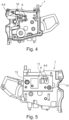
- 4 14 is an illustration of an internal view of the clamp module 1 viewed from a clamp side according to the present disclosure. In other words is in 4 a section through the clamping module 1 is shown. In this case, the printed circuit board is arranged on the side not facing the viewer and the cut is made in such a way that the optical window 10 can be seen.
- the clamping module 1 therefore shows the optical window 10, which consists of two plastic lenses and behind which the photodetector 8 and the first light source 4 and the second light source 6 are arranged.
- figure 5 14 is an illustration of an external view of the clamp module 1 viewed from the printed circuit board 11 side according to the present disclosure.
- the optical window 10 and the "recording" of the printed circuit board 11 for attachment to the clamping module 1 is shown schematically. That means, figure 5 is in contrast to 4 shown from the other side.
- the fastening means 13 are shown.
- the optical windows 10 or recesses can be seen, through which the light beams 5 and 6 of the first light source 4, the second light source 6 and the photodetector 8 are shown.
- the light sources 4 and 6 and the photodetector 8 are not shown directly, but only their position if the printed circuit board 11 is placed in the receptacle.
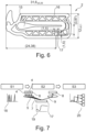
- the hose clamp 2 has a tapered elongated hole 15 through which an infusion hose runs.
- the infusion tube is not closed at one end of the elongated hole 15 and is compressed when it is passed to the other end of the Slot 15 is pushed.
- the hose clamp 2 is in an open state. In this state, the hose clamp 2 is pushed into the clamp module 1.
- the hook shown on tubing clamp 2 snaps into an eyelet on the front cover (at the same time a pump-side clamp is closed to prevent free flow).
- the front flap is opened, the hose clamp 2 pulls over the infusion hose and thus closes the passage.
- Reference number 16 relates here only to a reinforcement of the hose clamp 2 itself.
- the measuring point 17 is provided and designed to reflect the at least one first light beam 5 and the at least one second light beam 7 and to send the reflected light 9 back to the photodetector 8 .
- the total length displayed (31.6mm) corresponds to a total length for detecting that the hose clamp 2 is inserted into the clamping module.
- FIG. 12 is a block diagram representation of a color measurement and its implementation within an infusion pump, in accordance with the present disclosure.
- a first step S1 the sample or the measuring point 17 of the hose clamp 2 is sequentially illuminated.
- the sequential illumination results in illumination spectra as shown with reference numeral 18.
- the at least one first light beam 5 strikes in the colors red, green and blue, starting from of the first light source 4 and the second light beam 7, starting from the second light source 6, onto the measuring point 17.
- the measuring point 17 reflects in a step S2 and the reflected light 9 strikes the photodetector 8, which records the spectral properties of the material according to the reference number 19.
- a third step S3 a remission spectrum generates a photocurrent in the photodetector 8.
- the resulting signal is output in an evaluation spectrum according to reference number 20.
Landscapes
- Health & Medical Sciences (AREA)
- Heart & Thoracic Surgery (AREA)
- Animal Behavior & Ethology (AREA)
- General Health & Medical Sciences (AREA)
- Biomedical Technology (AREA)
- Engineering & Computer Science (AREA)
- Hematology (AREA)
- Life Sciences & Earth Sciences (AREA)
- Veterinary Medicine (AREA)
- Anesthesiology (AREA)
- Public Health (AREA)
- Vascular Medicine (AREA)
- Pulmonology (AREA)
- Physics & Mathematics (AREA)
- Fluid Mechanics (AREA)
- Infusion, Injection, And Reservoir Apparatuses (AREA)
Abstract
Description
- Die vorliegende Offenbarung betrifft ein Klemmmodul/ Klemmenmodul einer oder für eine medizinische Pumpe, insbesondere Infusionspumpe, welches ein elektro-optisches System zum Erkennen einer Schlauchklemme eines in das Klemmmodul einsetzbaren Infusionseinmalartikels aufweist, und so die Art des Infusionseinmalartikels zu bestimmen. Ferner betrifft die vorliegende Offenbarung ein Verfahren zur Erkennung einer Schlauchklemme basierend auf einer Farbe mittels eines Messalgorithmus nach Einschub der Schlauchklemme in eine medizinische Pumpe.
- Infusionspumpen und Infusionssets enthalten oft eine Schiebeklemme/ Schlauchklemme. Die Schlauchklemme ist hierbei Teil des Infusionssets und interagiert mit dem Schlauch des Infusionssets, um selektiv einen freien Fluss durch den Infusionsschlauch zu verhindern. Häufig wird eine solche Schlauchklemme durch die Pumpe selbst im Rahmen eines Einsetzvorgangs des Infusionssets in die Pumpe betätigt, etwa mittels einer Frontklappe der Pumpe bei deren Schließbewegung. Alternativ kann die Schlauchklemme aber auch manuell unabhängig von irgendwelchen Schließmechanismen an der Pumpe betätigbar sein.
- Die Schlauchklemme weist typischerweise ein sich verjüngendes Langloch auf, durch das der Schlauch verläuft. Der Schlauch ist an einem Ende des Lochs nicht verschlossen und wird zusammengedrückt, wenn er zum anderen Ende des Lochs geschoben wird. In einigen Fällen dient die als Gleitklemme ausgebildete Schlauchklemme funktional als Schlüssel zum Ein- und Ausschalten der Infusionspumpe und kann dabei helfen, den Schlauch des Infusionssets im Pumpenkanal zu befestigen. Bei einigen Pumpen dient die Schlauchklemme/ Schiebeklemme auch als Schlüssel zum Öffnen der Pumpentür, um den Infusionsschlauch zu laden oder zu entladen. Die Pumpentür wird entriegelt, indem ein Teil der Schlauchklemme/ Schiebeklemme in einen Schlitz im Pumpenkörper gedrückt wird. Durch Drücken der Schlauchklemme/ Schiebeklemme in den Schlitz wird der Schlauch zum schmalen Ende des konischen Lochs gedrückt, wodurch der Schlauch geschlossen wird. Somit bietet die Schlauchklemme ein Maß an Sicherheit, indem sie einen freien Fluss verhindert, da sie den Schlauch beim Öffnen der Pumpentür zusammendrückt.
- Gleit-/Schiebeklemmen dieser Gattung sind oft passend für eine bestimmte Pumpe und stellen somit sicher, dass nur kompatible Infusionssets mit dieser Pumpe verwendet werden. Vor dem Hintergrund ist es von Bedeutung, sicherstellen zu können, dass die richtige Schlauchklemme (Gleit-/Schiebeklemme) verwendet wird bzw. erkennen zu können, welche Art an Infusionsschlauchset eingesetzt ist.
- Aus dem Stand der Technik ist die
US 9,272,129 B2 - Zudem ist aus der
US 2006/0224128 A1 ein System und ein Verfahren zum automatischen Verabreichen eines Infusats an einen Patienten offenbart. Das System umfasst ein Infusionsset und ein Infusionsgerät. Eine an einer Infusionsset-Komponente angeordnete Signalisierungskomponente identifiziert ein Verabreichungsprotokoll für das Infusionsset. Eine operativ mit der Infusionsvorrichtung verbundene Erfassungsvorrichtung erfasst die Signalisierungskomponente und identifiziert das Verabreichungsprotokoll. Das Infusionsgerät wird dann so konfiguriert, dass es gemäß dem Verabreichungsprotokoll arbeitet. - Der Stand der Technik bringt jedoch den Nachteil mit sich, dass die Farberkennung der Schlauchklemme unzureichend ist, da Farbspektren bei reiner RGB Beleuchtung nicht ausreichend getrennt werden können.
- Vor dem Hintergrund liegt der vorliegenden Offenbarung die objektiv technische Aufgabe zugrunde, die Nachteile aus dem Stand der Technik zu beseitigen oder zumindest zu vermindern, insbesondere eine medizinische Pumpe bereitzustellen, welche ein sicheres Erkennen einer eingelegten Schlauchklemme/ Schiebeklemme ermöglicht.
- Daher betrifft die vorliegende Offenbarung ein Klemmmodul einer oder für eine medizinische Pumpe, insbesondere Infusionspumpe, welches ein elektro-optisches System zum Erkennen einer Schlauchklemme eines in das Klemmmodul einsetzbaren Infusionseinmalartikels, insbesondere eines Infusionsschlauchs hat oder ausbildet, wobei die Schlauchklemme eine vorbestimmte Farbe und/oder eine optische/optisch erkennbare Markierung hat. Das Klemmmodul hat eine erste Lichtquelle zum Senden zumindest eines ersten Lichtstrahls, eine zweite Lichtquelle zum Senden zumindest eines zweiten Lichtstrahls, wobei die zweite Lichtquelle zur ersten Lichtquelle unterschiedlich ausgebildet ist, bzw. die Frequenzen/ Wellenlängen der zumindest zwei Lichtstrahlen unterschiedlich zueinander sind, einen Photodetektor zum Empfangen eines reflektierten Lichts, und ein optisches Fenster zur Bündelung des zumindest ersten Lichtstrahls und/ oder des zumindest zweiten Lichtstrahls auf dem Infusionseinmalartikel sowie des reflektierenden Lichts in dem Photodetektor.
- In anderen Worten betrifft die vorliegende Erfindung ein Klemmmodul einer medizinischen Pumpe, insbesondere einer Infusionspumpe, mit einem elektro-optischen System zur Erkennung der Farbe/Farbmarkierung einer Schlauchklemme eines Infusionseinmalartikels und zur entsprechenden Steuerung der medizinischen Pumpe/ Infusionspumpe. Dabei wird die Schlauchklemme innerhalb der medizinischen Pumpe/ Infusionspumpe mit unterschiedlichen Lichtquellen/unterschiedlichen Wellenlängen beleuchtet und über das reflektierende Licht, die Farbe der Schlauchklemme ermittelt und auf die Art des Infusionseinmalartikels geschlossen.
- Beim Einlegen des Infusionseinmalartikels wird der Infusionseinmalartikel über das Erkennungsmerkmal von einem Sensor und einer Kontrolleinheit in der Infusionspumpe erkannt und zur Aktivierung von Parametern in der Kontrolleinheit der Infusionspumpe genutzt. Diese Parameter sind zum Beispiel
- Parameter zur Steuerung der Druckerkennung,
- Parameter zur Steuerung der Lufterkennung,
- Parameter zur Definition der maximalen Verweildauer des Infusionseinmalartikels und/ oder
- Parameter zu Air-Stop-Filter (ja/nein).
- Die zu aktivierenden Parameter können in einem Einmalartikeldatensatz hinterlegt sein. Die Pumpe ermöglicht dem Anwender, die Infusion über die Eingabevorrichtung und das Display zu definieren und zu überwachen. In anderen Worten bedeutet das eine Erweiterung des spektralen Raums bei optisch ähnlichen Farbspektren.
- Die vorliegende Offenbarung bringt die Vorteile bzw. Verbesserungen mit sich, dass die Farbe der Schlauchklemme/ Schiebeklemme sowohl für den Nutzer/ Anwender als auch das Gerät nutzbar/ erkennbar ist. Somit bietet die vorliegende Offenbarung gleichzeitig eine Maschinenlesbarkeit und eine Nutzerlesbarkeit. Durch die vorzugsweise zusätzliche optische Markierung lässt sich ein Abbildungsraum erweitern und die Farben entsprechend trennen.
- Weitere vorteilhafte Ausführungsformen sind nachfolgend gemäß den Unteransprüchen beschrieben.
- Es ist bevorzugt, wenn die erste Lichtquelle eine RGB-LED, vorzugsweise eine kombinierte RGB-LED, ist und die zweite Lichtquelle eine IR-LED, insbesondere mit einer Wellenlänge von 950nm ± 42nm, ist, wobei die erste Lichtquelle drei LEDs aufweist, welche derart ausgebildet sind, um den ersten Lichtstrahl als einen roten, insbesondere einer Wellenlänge von 630nm ± 16nm, einen grünen, insbesondere einer Wellenlänge von 520nm ± 33nm und/ oder einen blauen, insbesondere einer Wellenlänge von 467nm ± 25nm ersten Lichtstrahl auszugeben.
- In anderen Worten bedeutet das, dass das elektro-optische System innerhalb der medizinischen Pumpe bzw. innerhalb des in die medizinische Pumpe einsetzbare/eingesetzte Klemmmodul die kombinierte RGB-LED, die IR-LED, den Photodetektor und das optische Fenster zur Bündelung des Lichtstrahls auf der Schlauchklemme sowie des reflektierten Lichts in den Photodetektor hat oder ausbildet. Zur differenzierten Farberkennung werden daher RGB-Signale und IR-Signale zur Beleuchtung der Schlauchklemme genutzt.
- Demzufolge werden in der vorliegenden Offenbarung die folgenden Wellenlängen verwendet:
- Rot: Hauptwellenlänge 630 nm ± 16 nm
- Grün: Hauptwellenlänge 520 nm ± 33 nm
- Blau: Hauptwellenlänge 467 nm ± 25 nm
- Infrarot (IR): Hauptwellenlänge 950 nm ± 42 nm
- Bezüglich der eingesetzten Materialien ergibt sich daraus folgende Übersicht (Lookup-Table) zu den Materialeigenschaften. Diese Anteile sind abhängig von dem Material. Daher ist es naheliegend, dass sich die Anteile bei Einsatz anderer Materialien ändern. In anderen Worten werden in Abhängigkeit des eingesetzten Materials und der Farb-/Pigmentbeimischung der Klemme die eingestrahlten Hauptwellenlängen an der Klemme reflektiert. Diese Reflektion wird in Form einer Look-up Tabelle in der Pumpe hinterlegt, um über einen relativen Vergleich der Einzelfarben (RGB, IR) zueinander, die Farbe der Schlauchklemme über die Look-up Tabelle zu ermitteln.
- Dies bedeutet, dass bei Verwendung anderer Materialien in der Pumpe eine neue Lookup-Table eingepflegt werden muss. Es ist jedoch bevorzugt, wenn die sich daraus ergebenden Remissionsspektren in ihren Eigenschaften unverändert bleiben.
Farbe Normierte Remission für blau (Hauptwellenlänge 466 nm) Normierte Remission für grün (Hauptwellenlänge 518 nm) Normierte Remission für rot (Hauptwellenlänge 629 nm) Magenta [13.7 % .. 18.1 %] [8.3 % .. 10.1 %] [52.5 % .. 73.0 %] Grün [64.5 % .. 86.5 %] [79.3 % .. 100.8 %] [15.5 % .. 19.5 %] Grau [108.0 % .. 126.0 %] [113.5 % .. 133.3 %] [104.5 % .. 122.6 %] Rot (mit IR Absorber) [23.3 % .. 28.4 %] [22.1 % .. 26.4 %] [170.7 % .. 208.6 %] Weiß [226.7 % .. 265.8 %] [231.9 % .. 271.7 %] [217.2 % .. 257.7 %] Gelb (mit IR Absorber) [35.1 % .. 52.6 %] [106.8 % .. 130.8 %] [113.0 % .. 132.6 %] Pink [66.0 % .. 84.6 %] [39.9 % .. 49.6 %] [55.3 % .. 67.2 %] Blau Alternative Option Alternative Option Alternative Option Orange Alternative Option Alternative Option Alternative Option - Es ist von Vorteil, wenn die optische Markierung ein Infrarot-Marker ist.
- Es ist bevorzugt, wenn das optische Fenster aus Kunststoff ist.
- Es ist vorteilhaft, wenn die erste Lichtquelle, die zweite Lichtquelle und der Photodetektor auf einer Leiterplatine angeordnet sind, welche in/ an das Klemmmodul integrierbar/ anbringbar ist.
- Es ist bevorzugt, wenn die drei LEDs der ersten Lichtquelle eine lineare Anordnung auf der Leiterplatine haben und in einem so geringen Abstand angeordnet sind, um durch das optische Fenster auszuleuchten, vorzugsweise in einem Abstand von 0,23mm.
- In anderen Worten sind die kombinierte RGB-LED und die IR-LED dicht zusammen platziert, damit ihre Ausleuchtung durch das optische Fenster ermöglicht wird. Zudem ist eine RGB-LED verbaut, die es ermöglicht, alle Leuchtquellen in einer Flucht, also gemäß einer linearen Anordnung der Chiplagen, anzuordnen. Der Abstand der RGB-LEDs zueinander beträgt ca. 0,23 mm. Das Layout der Platine und die Auswahl der LEDs ist so gewählt, um möglichst kleine Abmessungen zu haben und um sich in das Klemmenmodul der medizinischen Pumpe/ Infusionspumpe integrieren zu lassen.
- Es ist von Vorteil, wenn das optische Fenster zwischen der Schlauchklemme/ Schiebeklemme und der Leiterplatine derart angeordnet ist, dass der zumindest eine erste Lichtstrahl und der zumindest eine zweite Lichtstrahl durch das optische Fenster auf die Schlauchklemme, insbesondere die optische Markierung, trifft und die Schlauchklemme, insbesondere die optische Markierung, den zumindest einen ersten Lichtstrahl und den zumindest einen zweiten Lichtstrahl reflektiert und das reflektierte Licht durch das optische Fenster auf den Photodetektor trifft. Ferner ist es bevorzugt, wenn die Anordnung derart vorgesehen ist, dass das optische Fenster und die Anordnung von Sende-LEDs und Photodetektor auch dafür sorgen, dass keine direkte Lichteinkoppelung zwischen Photodetektor und Sende-LEDs vorhanden ist.
- In anderen Worten wird durch die Anordnung der Lichtquellen, des Photodetektors und des zugehörigen optischen Fensters sichergestellt, dass der Reflexionsbereich optimal ausgeleuchtet und dessen Reflexion gebündelt am Photodetektor aufgenommen wird. Das optische Fenster dient daher zum Senden und Empfangen zumindest eines Lichtstrahls und des reflektierten Lichts.
- Ferner betrifft die vorliegende Offenbarung eine medizinische Pumpe, insbesondere Infusionspumpe, mit einem Klemmmodul gemäß einem der vorstehenden Aspekte.
- Des Weiteren betrifft die vorliegende Offenbarung ein Verfahren zur Erkennung einer Schlauchklemme basierend auf zumindest einer Farbe mittels eines Messalgorithmus nach Einschub der Schlauchklemme in eine medizinische Pumpe, insbesondere Infusionspumpe, um die Art des damit verwendeten Infusionseinmalartikels, insbesondere eines Infusionsschlauchs, zu bestimmen. Ein erster Schritt (S1) ist die Messung einer Temperatur. In einem zweiten Schritt (S2) wird das Umgebungslicht gemessen und die Umgebungshelligkeit ermittelt. Anschließend folgt im dritten Schritt (S3) eine sequentielle Beleuchtung mit rotem, grünen, blauem und IR-Licht und Messung der Reflexion an der Schlauchklemme/ Schiebeklemme. In einem letzten Schritt (S4) erfolgt eine Auswertung und Bestimmung der Farbe durch gemessene Reflexion und anschließendem Abgleich mit einer in der medizinischen Pumpe hinterlegten Auswertetabelle.
- In anderen Worten wird nach Einschub der Schlauchklemme folgendes durchgeführt:
- Temperaturmessung;
- Messung des Umgebungslichts (Dunkelkorrektur) und daraus Ermittlung der Umgebungshelligkeit;
- Sequentielle Messung der Reflexion an der Schlauchklemme/ Schiebeklemme, wenn sie nacheinander mit, Rot, Grün, Blau, Infrarotem (IR) Licht beleuchtet wird;
- Die Farbe wird durch Auswertung der gemessenen Informationen (separate Einzelfarbmessung) und anschließendem Abgleich mit einer in der Infusionspumpe abgelegten Auswertetabelle bestimmt. Die Auswertetabelle (Lookup-Table) ermöglicht ausgehend von den Messwerten (Remissionswerten) eine Zuordnung der Farbe.
- Es ist bevorzugt, wenn Kalibrierdaten in einem Mikroprozessor vorliegen, welche zur Initialisierung des Messalgorithmus verwendet werden, und die Auswertetabelle eine optische Charakterisierung der eingesetzten Schlauchklemme/ Schiebeklemme bezüglich derer Reflexion aufweist und mittels eines darin hinterlegten Wertebereichs Schwankungen der Messung ausgleichbar sind.
- In anderen Worten ist es vorgesehen, dass in die Berechnung der Einzelfarbmessungen die gemessenen Remissionsspektren eingehen. Die Messwerte liegen als sog. "Counts" vor und sind letztlich die Analog-zu-Digital-Messwerte des Photodetektors. Die Messungen sind weiterhin abhängig von den Kalibrierdaten (Weißabgleich), der Umgebungstemperatur und dem Dunkelwert (Umgebungslichteinfluss). Daraus resultiert die nachfolgende Berechnungsgrundlage.
- Eine Eingangsvoraussetzung ist das Vorliegen der Kalibrierdaten, vorzugsweise inklusive der Temperaturmessung. Die Kalibrierdaten werden zur "Initialisierung" des Messalgorithmus benötigt. Die Kalibrierdaten erzeugen einen Reflektionskoeffizienten über ein Weißnormal, der in die Berechnung einfließt und in der Gesamtnäherung abhängig von Temperatur und Lichtstärke ist.
- Ferner werden die nachfolgenden Messwerte aufgezeichnet. Ein erster Messwert ist die Temperaturmessung (Tmess) und ein zweiter Messwert ist die Beleuchtung der Schlauchklemme nach Einzelfarben (RGB). Der zweite Messwert betrifft Analog/DigitalWerte pro Farbe. In einem weiteren Messwert wird der Dunkelwert aufgezeichnet, welcher einen Messwert beschreibt, der ohne Ausleuchtung der LEDs am Photodetektor anliegt. Es ist ebenfalls nötig, Licht, das von außen in das Klemmmodul eindringen kann, bei der Messung zu kompensieren (entspricht dem vorstehenden Umgebungslicht). Daraufhin erfolgt eine Korrektur des Messsignals bezüglich des Dunkelwerts. Die Messsignale selbst sind die empfangenen Daten an dem Photodetektor zu einem Messzeitpunkt für jede einzelne Farbe. Anschließend folgt eine Temperaturkompensation der Messwerte über ein Polynom, das die Temperaturverläufe der LEDs annähert. Das heißt, die LEDs und deren Lichtstrom verhalten sich für unterschiedlichen Temperaturen unterschiedlich. Daher wird der Verlauf dieser Termperaturdegardation für jede Farbe über eine polynomisch gefittete Temperaturkurve der LED-Farben (Polynom 3. Grades) angenähert. Basierend darauf wird pro Farbe eine Reflektivitätsberechnung durchgeführt, welche auf die Kalibrierdaten normiert ist. Diese Reflektivitätswerte werden mit den in der Lookup-/ Auswertetabelle hinterlegten Minimum- und Maximum-Werten verglichen. Der Vergleich berücksichtigt zusätzliche, mögliche Verschmutzungen, weshalb bei der Farbzuordnung das relative Verhältnis aus Mess- und Auswertetabelle-Wert betrachtet wird. Hierbei können entweder alle Messwerte der vier Farben in die Farbbestimmung eingehen. Alternativ ist auch denkbar, die Intensität/ Amplitude des Skalierungsfaktors zu wählen, wenn es keine eindeutige Farbzuordnung geben sollte.
- Die Lookup-Table wird mit der Materialqualifizierung der Schlauchklemme/ Schiebeklemme erzeugt und vermessen. Sie beinhaltet die optische Charakterisierung des eingesetzten Materials bezüglich ihrer Reflexion der Farben rot, grün, blau und IR. Die Auswertetabelle umfasst einen Wertebereich (min./max. Wert), um Schwankungen bei der Farbemessung ausgleichen zu können. Weitere Informationen zu den Wellenlängen sind vorstehend bereits beschrieben worden. Das Einbringen eines IR-Anteils ist nötig, um die Farben Rot und Gelb von anderen Farben mit identischen Reflexionseigenschaften (Remissionsspektrum) unterscheiden zu können. Ohne die eingebrachten IR-Marker, welche homogen in die Schlauchklemme/ Schiebeklemme eingebracht sind, wären die Remissionsspektren zwar in ihrer Amplitude unterschiedlich, jedoch der eigentliche Verlauf und das Verhältnis aller Farben zueinander identisch. Eine eindeutige Erkennung wäre dadurch nicht gegeben.
- Zusammenfassend beruht der Messalgorithmus auf der Idee, die Schlauchklemme/ Schiebeklemme innerhalb der Infusionspumpe mit unterschiedlichen Lichtquellen zu beleuchten und über das reflektierende Licht, die Farbe/Farben der Klemme zu ermitteln. Hierzu ist es jedoch mindestens einmalig nötig, eine Kalibrierung des optischen Systems durchzuführen, um die Einflüsse der Einbausituation (hier z.B. Toleranz der Einbaulage) sowie die Toleranzen der elektronischen Bauteile auszugleichen. Durch die Kalibrierung wird ein Offset-Wertepaar generiert, das im Messalgorithmus zur Kompensation verwendet wird.
-
-
Fig. 1 ist eine Darstellung eines Klemmmoduls mit einer Leiterplatine gemäß der vorliegenden Offenbarung; -
Fig. 2 ist eine Darstellung eines Höhenschnitts durch das Klemmmodul wie inFig. 2 gezeigt gemäß der vorliegenden Offenbarung; -
Fig. 3 ist eine Darstellung des Aufbaus einer Leiterplatine gemäß der vorliegenden Offenbarung; -
Fig. 4 ist eine Darstellung einer Innenansicht des Klemmmoduls von einer Klemmseite aus gesehen gemäß der vorliegenden Offenbarung; -
Fig. 5 ist eine Darstellung einer Außenansicht des Klemmmoduls von der Seite der Leiterplatine aus gesehen gemäß der vorliegenden Offenbarung; -
Fig. 6 ist eine schematische Darstellung einer Schlauchklemme; und -
Fig. 7 ist eine Darstellung eines Blockschaltbildes einer Farbmessung und deren Umsetzung innerhalb einer Infusionspumpe gemäß der vorliegenden Offenbarung. - Nachstehend werden Ausführungsbeispiele der vorliegenden Offenbarung auf der Basis der zugehörigen Figuren beschrieben.
-
Fig. 1 ist eine Darstellung eines Klemmmoduls 1 mit einer Leiterplatine 11 gemäß der vorliegenden Offenbarung. Das Klemmmodul 1 ist derart ausgebildet, um in eine medizinische Pumpe, insbesondere Infusionspumpe, einsetzbar/ integrierbar zu sein. An dem Klemmmodul 1 ist eine Leiterplatine 11 angebracht bzw. integriert. Die Leiterplatine 11 ist mit deren Oberseite dem Klemmmodul 1 zugewandt. Die Leiterplatine 11 ist mit zumindest einem Befestigungsmittel 13, gemäßFig. 1 mit zwei Befestigungsmittels 13 an dem Klemmmodul 1 fixiert. Auf der Leiterplatine 11 ist ein erster Teil eines elektro-optisches Systems platziert und ein zweiter Teil des elektro-optischen Systems ist Teil des Klemmmoduls 1. Dies ist inFign. 2 und 3 detaillierter beschrieben. - Darüber hinaus ist in
Fig. 1 ein Flachbandkabel 12 gezeigt, welches auf ein Mainboard/ eine Hauptplatine der medizinischen Pumpe gesteckt wird. Ferner ist auf der Leiterplatine 11 zu erkennen, wo ein Mikroprozessor 14 angeordnet ist. Details hierzu sind zuFig. 3 näher beschrieben. -
Fig. 2 ist eine Darstellung eines Höhenschnitts durch das Klemmmodul 1 wie inFig. 1 gezeigt gemäß der vorliegenden Offenbarung. InFig. 1 ist eine Schnittachse A eingezeichnet. Basierend auf der Schnittachse A istFig. 2 in einer Draufsicht abgebildet. InFig. 2 ist daher die Leiterplatine 11 auf der dem Betrachter abgewandten Seite des Klemmmoduls 1 dargestellt. Im Zusammenhang mit der Leiterplatine 11 ist das eine Befestigungsmittel 13 (Schraube, Niete, etc.) zu erkennen, welches dazu dient, die Leiterplatine 11, vorzugsweise mittels Schrauben oder Löten, an dem Klemmmodul 1 zu fixieren. - In
Fig. 2 ist ferner gezeigt, dass auf der Leiterplatine 11 eine erste Lichtquelle 4, eine zweite Lichtquelle 6 mit entsprechender Sendeoptik und ein Photodetektor 8 mit entsprechender Empfangsoptik angeordnet sind. Zwischen der ersten Lichtquelle 4, der zweiten Lichtquelle 6 und dem Photodetektor 8 ist das optische Fenster 10 angeordnet. Das optische Fenster 10 ist derart ausgebildet, dass zumindest ein erster Lichtstrahl 5 und ein zweiter Lichtstrahl 7 gebündelt durch das optische Fenster 10 auf die einzulegende (hier nicht abgebildete) Schlauchklemme 2 (hier nicht abgebildet, sieheFig. 6 ) trifft. Ferner besteht das optische Fenster 10 aus zwei Kunststofflinsen und ist dazu ausgebildet, dass ein von der Schlauchklemme 2 reflektiertes Licht 9 wiederum gebündelt von dem Photodetektor 8 auf der Leiterplatine 11 empfangen wird. Der zumindest eine erste Lichtstrahl 5 und der zweite Lichtstrahl 7 ist inFig. 2 als ein Pfeil in Richtung weg von der Leiterplatine 11 dargestellt. Das reflektierte Licht 9 ist inFig. 2 als ein Pfeil in Richtung hin zu der Leiterplatine 11 dargestellt. Das optische Fenster 10 bildet eine derartige Öffnung in dem Gehäuse des Klemmmoduls 1, um die Lichtstrahlen 5 und 7 sowie das reflektierte Licht 9 durchzulassen. - Vor dem Hintergrund ist die Anordnung der Leiterplatine 11, insbesondere in Bezug auf die erste Lichtquelle 4 und die zweite Lichtquelle 6 sowie den Photodetektor 8, zu dem Klemmmodul 1 und der in das Klemmmodul 1 einzulegenden Schlauchklemme klar definiert.
-
Fig. 3 ist eine Darstellung des Aufbaus einer Leiterplatine 11 gemäß der vorliegenden Offenbarung. Die Leiterplatine 11 ist rückseitig dargestellt. Die Leiterplatine inFig. 3 zeigt die Anordnung der ersten Lichtquelle 4, der zweiten Lichtquelle 6 und des Photodetektors 8 zueinander. Hierbei wird ersichtlich, dass die erste Lichtquelle 4 und die zweite Lichtquelle 6 nebeneinander in Breitenrichtung der Leiterplatine 11 angeordnet sind. Der Photodetektor 8 ist bezüglich der ersten Lichtquelle 4 und der zweiten Lichtquelle 6 in Längsrichtung hierzu angeordnet. - Ferner zeigt
Fig. 3 die beiden Befestigungsmittel 13, sowie einen Mikroprozessor 14, welcher ebenfalls auf der Leiterplatine 11 angeordnet ist. -
Fig. 4 ist eine Darstellung einer Innenansicht des Klemmmoduls 1 von einer Klemmseite aus gesehen gemäß der vorliegenden Offenbarung. In anderen Worten ist inFig. 4 ein Schnitt durch das Klemmmodul 1 dargestellt. Hierbei ist die Leiterplatine auf nicht dem Betrachter zugewandten Seite angeordnet und der Schnitt ist derart getätigt, dass das optische Fenster 10 zu sehen ist. Das Klemmmodul 1 zeigt daher das optische Fenster 10, welches aus zwei Kunststofflinsen besteht und hinter welchem der Photodetektor 8 und die erste Lichtquelle 4 sowie die zweite Lichtquelle 6 angeordnet sind. -
Fig. 5 ist eine Darstellung einer Außenansicht des Klemmmoduls 1 von der Seite der Leiterplatine 11 aus gesehen gemäß der vorliegenden Offenbarung. InFig. 5 ist das optische Fenster 10 sowie die "Aufnahme" der Leiterplatine 11 zur Befestigung an dem Klemmmodul 1 schematisch dargestellt. Das heißt,Fig. 5 ist im Gegensatz zuFig. 4 von der anderen Seite gezeigt. Zudem sind die Befestigungsmittel 13 gezeigt. Auf der dargestellten Außenseite des Klemmmoduls 1 zur Aufnahme der Leiterplatine 11 sind die optischen Fenster 10 bzw. Aussparungen zu erkennen, durch die der Lichtstrahl 5 und 6 der ersten Lichtquelle 4, der zweiten Lichtquelle 6 und des Photodetektors 8 dargestellt. Die Lichtquelle 4 und 6 sowie der Photodetektor 8 sind nicht direkt gezeigt, sondern lediglich deren Position sofern die Leiterplatine 11 in die Aufnahme eingelegt wird. -
Fig. 6 ist eine schematische Darstellung einer Schlauchklemme 2. Die Schlauchklemme 2 weist ein sich verjüngendes Langloch 15 auf, durch das ein Infusionsschlauch verläuft. Der Infusionsschlauch ist an einem Ende des Langlochs 15 nicht verschlossen und wird zusammengedrückt, wenn er zum anderen Ende des Langlochs 15 geschoben wird. Beim Einlegen des Einmalartikels ist die Schlauchklemme 2 in einem geöffneten Zustand. In diesem Zustand wird die Schlauchklemme 2 in das Klemmenmodul 1 eingeschoben. Wenn eine Frontklappe der medizinischen Pumpe geschlossen wird, rastet der an der Schlauchklemme 2 gezeigte Haken in einer Öse der Frontklappe ein (und gleichzeitig wird eine pumpenseitige Klemme geschlossen, um den freien Fluss zu verhindern). Beim Öffnen der Frontklappe zieht sich die Schlauchklemme 2 über den Infusionsschlauch und verschließt damit den Durchgang. Parallel öffnet die medizinische Pumpe 1 ihre pumpenseitige Klemme. Beides zusammen verhindert weiterhin den freien Fluss.. Das Bezugszeichen 16 betrifft hierbei lediglich eine Verstärkung der Schlauchklemme 2 selbst. In der Nähe hin zum schmalen Ende des Langlochs 15 weist die Schlauchklemme 2 einen Messpunkt 17 auf. Der Messpunkt 17 ist dazu vorgesehen und ausgebildet, um den zumindest einen ersten Lichtstrahl 5 und den zumindest einen zweiten Lichtstrahl 7 zu reflektieren und das reflektierte Licht 9 an den Photodetektor 8 zurückzusenden. - Ferner sind in
Fig. 6 die Größenordnungen des Klemmmoduls 2 angegeben. Die inFig. 6 angezeigte Gesamtlänge (31 ,6mm) entspricht einer totalen Länge für die Erkennung, dass die Schlauchklemme 2 in das Klemmmodul eingesetzt ist. -
Fig. 7 ist eine Darstellung eines Blockschaltbildes einer Farbmessung und deren Umsetzung innerhalb einer Infusionspumpe gemäß der vorliegenden Offenbarung. In einem ersten Schritt S1 erfolgt die sequentielle Beleuchtung der Probe bzw. des Messpunktes 17 der Schlauchklemme 2. Die sequentielle Beleuchtung ergibt Beleuchtungsspektre gemäß der Darstellung zu Bezugszeichen 18. Hierbei trifft der zumindest eine erste Lichtstrahl 5 in den Farben rot, grün und blau ausgehend von der ersten Lichtquelle 4 und der zweite Lichtstrahl 7 ausgehend von zweiten Lichtquelle 6 auf den Messpunkt 17. Der Messpunkt 17 reflektiert in einem Schritt S2 und das reflektierte Licht 9 trifft auf den Photodetektor 8, welcher die spektralen Eigenschaften des Materials gemäß dem Bezugszeichen 19 aufzeichnet. In einem dritten Schritt S3 erzeugt ein Remissionsspektrum einen Fotostrom in dem Photodetektor 8. Das daraus entstehende Signal wird in einem Auswertespektrum gemäß dem Bezugszeichen 20 ausgegeben. - Es ist bevorzugt, wenn thermoplastischer Kunststoff auf Basis von Polyolefin oder Polyoxymethylen mit den folgenden Eigenschaften verwendet werden:
- E-Modul: >1000MPa
- Streckgrenze: >27MPa
- Reibkoeffizienten anhand Stift-Schreibe Reibprüfung in Anlehnung an ASTM G115 und DIN EN ISO 7148-2Größe Wert Aufbau Prüfstift: Schiebeklemme Prüfplatte: Schlauchmaterial Messung 20 Zyklen Zyklus 1. Zustellbewegung (tR =2s) 2. Stillstand (tP = 2s) 3. Rückstellbewegung (tR = 2s) 4. Stillstand (tP = 2s) Reibweg 15mm Gleitgeschwindigkeit 450 mm/min Flächenpressung pN 2,7 +/- 0,1 MPa Schlauchmaterial PVC-P und TPU -
- (1)
- Klemmmodul
- (2)
- Schlauchklemme
- (3)
- Markierung
- (4)
- erste Lichtquelle
- (5)
- erster Lichtstrahl
- (6)
- zweite Lichtquelle
- (7)
- zweiter Lichtstrahl
- (8)
- Photodetektor
- (9)
- reflektiertes Licht
- (10)
- optisches Fenster
- (11)
- Leiterplatine
- (12)
- Displaykabel
- (13)
- Befestigungsmittel
- (14)
- Mikroprozessor
- (15)
- Langloch
- (16)
- Verstärkung
- (17)
- Messpunkt
- (18)
- Beleuchtungssprektren
- (19)
- Spektrale Eigenschaft des Materials
- (20)
- Auswertespektren
Claims (11)
- Klemmmodul (1) einer oder für eine medizinische Pumpe, insbesondere Infusionspumpe, welches ein elektro-optisches System ausbildet oder hat zum Erkennen einer, zumindest eine vorbestimmte Farbe und/oder eine optische Markierung (3) aufweisenden oder tragenden Schlauchklemme (2) eines in das Klemmmodul (1) einsetzbaren Infusionseinmalartikels, mit folgenden System-Komponenten:- eine erste Lichtquelle (4) zum Senden zumindest eines ersten Lichtstrahls (5),- eine zweite Lichtquelle (6) zum Senden zumindest eines zweiten Lichtstrahls (7), wobei die zweite Lichtquelle (6) zur ersten Lichtquelle (4) und/oder die Frequenz des ersten Lichtstrahls zur Frequenz des zweiten Lichtstrahls unterschiedlich ausgebildet ist,- einen Photodetektor (8) zum Empfangen eines am Infusionseinmalartikel (2), insbesondere an der Schlauchklemme (2) reflektierten Lichts (9), und- ein optisches Fenster (10) zur Bündelung des zumindest ersten Lichtstrahls (5) und/ oder des zumindest zweiten Lichtstrahls (7) auf dem Infusionseinmalartikel (2), insbesondere auf der Schlauchklemme (2) sowie des reflektierenden Lichts (9) in dem Photodetektor (8).
- Klemmmodul (1) gemäß Anspruch 1, dadurch gekennzeichnet, dass die erste Lichtquelle (4) eine RGB-LED, vorzugsweise eine kombinierte RGB-LED, ist und die zweite Lichtquelle (6) eine IR-LED, insbesondere mit einer Wellenlänge von 950nm ± 42nm, ist, wobei die erste Lichtquelle (4) drei LEDs aufweist, welche derart ausgebildet sind, um den ersten Lichtstrahl (5) als einen roten, insbesondere einer Wellenlänge von 630nm ± 16nm, einen grünen, insbesondere einer Wellenlänge von 520nm ± 33nm und/ oder einen blauen, insbesondere einer Wellenlänge von 467nm ± 25nm ersten Lichtstrahl (5) auszugeben.
- Klemmmodul (1) gemäß einem der Ansprüche 1 oder 2, dadurch gekennzeichnet, dass die optische Markierung (3) ein Infrarot-Marker ist.
- Klemmmodul (1) gemäß einem der Ansprüche 1 bis 3, dadurch gekennzeichnet, dass das optische Fenster (10) aus Kunststoff ist.
- Klemmmodul (1) gemäß einem der Ansprüche 1 bis 4, dadurch gekennzeichnet, dass die erste Lichtquelle (4), die zweite Lichtquelle (6) und der Photodetektor (8) auf einer Leiterplatine (11) angeordnet sind, welche in/ an das Klemmmodul (1) integrierbar/ anbringbar ist.
- Klemmmodul (1) gemäß Anspruch 5, dadurch gekennzeichnet, dass die drei LEDs der ersten Lichtquelle (4) eine lineare Anordnung auf der Leiterplatine (11) haben und in einem so geringen Abstand angeordnet sind, um durch das optische Fenster (10) auszuleuchten, vorzugsweise in einem Abstand von 0,23mm.
- Klemmmodul (1) gemäß Anspruch 5 oder 6, dadurch gekennzeichnet, dass das optische Fenster (10) zwischen der Schlauchklemme (2) und der Leiterplatine (11) derart angeordnet ist, dass der zumindest eine erste Lichtstrahl (5) und der zumindest eine zweite Lichtstrahl (7) durch das optische Fenster (10) auf die Schlauchklemme (2), insbesondere die optische Markierung (3), trifft und die Schlauchklemme (2), insbesondere die optische Markierung (3), den zumindest einen ersten Lichtstrahl (5) und den zumindest einen zweiten Lichtstrahl (7) reflektiert und das reflektierte Licht (9) durch das optische Fenster (10) auf den Photodetektor (8) trifft.
- Medizinische Pumpe, insbesondere Infusionspumpe, mit einem Klemmmodul (1) gemäß einem der vorstehenden Ansprüche.
- Verfahren zur Erkennung einer Schlauchklemme (2) basierend auf einer Farbe mittels eines Messalgorithmus nach Einschub der Schlauchklemme (2) in eine medizinische Pumpe, insbesondere Infusionspumpe, mit den folgenden Schritten:- Messung einer Temperatur;- Messung des Umgebungslichts und Ermittlung der Umgebungshelligkeit;- sequentielle Beleuchtung mit rotem, grünen, blauem und IR-Licht und Messung der Reflexion an der Schlauchklemme (2); und- Auswertung und Bestimmung der Farbe durch gemessene Reflexion und anschließendem Abgleich mit einer in der medizinischen Pumpe hinterlegten Auswertetabelle.
- Verfahren gemäß Anspruch 9, dadurch gekennzeichnet, dass Kalibrierdaten in einem Mikroprozessor vorliegen, welche zur Initialisierung des Messalgorithmus verwendet werden, und die Auswertetabelle eine optische Charakterisierung der eingesetzten Schlauchklemme (2) bezüglich derer Reflexion aufweist und mittels eines darin hinterlegten Wertebereichs Schwankungen der Messung ausgleichbar sind.
- Schlauchklemme (2) zum Einsetzen in das Klemmmodul (1) gemäß einem der vorhergehenden Ansprüche, dadurch gekennzeichnet, dass die vorbestimmte Farbe der Schlauchklemme (2) derart ausgebildet und vorgesehen ist, um von einem Algorithmus nutzbar zu sein und die optische Markierung vorzugsweise dazu vorgesehen und ausgebildet ist, um zusätzlich zur Trennung ähnlicher Farben und/oder Reflexionsspektren zu dienen.
Applications Claiming Priority (1)
| Application Number | Priority Date | Filing Date | Title |
|---|---|---|---|
| DE102021215067.5A DE102021215067A1 (de) | 2021-12-28 | 2021-12-28 | IV Systems - Infusionspumpe zur Erkennung der Farbe einer Schlauchklemme mit IR-Markern |
Publications (1)
| Publication Number | Publication Date |
|---|---|
| EP4205779A1 true EP4205779A1 (de) | 2023-07-05 |
Family
ID=84604192
Family Applications (1)
| Application Number | Title | Priority Date | Filing Date |
|---|---|---|---|
| EP22216745.4A Pending EP4205779A1 (de) | 2021-12-28 | 2022-12-27 | Iv systems - infusionspumpe zur erkennung der farbe einer schlauchklemme mit ir-markern |
Country Status (4)
| Country | Link |
|---|---|
| US (1) | US20230201557A1 (de) |
| EP (1) | EP4205779A1 (de) |
| CN (1) | CN116350880A (de) |
| DE (1) | DE102021215067A1 (de) |
Cited By (1)
| Publication number | Priority date | Publication date | Assignee | Title |
|---|---|---|---|---|
| EP4599863A1 (de) | 2024-02-12 | 2025-08-13 | B. Braun Melsungen AG | Medizinische vorrichtung |
Families Citing this family (3)
| Publication number | Priority date | Publication date | Assignee | Title |
|---|---|---|---|---|
| DE102024121815A1 (de) * | 2024-07-31 | 2026-02-05 | B. Braun Melsungen Aktiengesellschaft | Medizinisches Überleitungssystem für eine medizinische Schlauchpumpe, medizinische Schlauchpumpe, und Verfahren für eine medizinische Schlauchpumpe |
| EP4710964A1 (de) * | 2024-09-16 | 2026-03-18 | B. Braun Melsungen AG | Medizinisches überleitungssystem für eine medizinische pumpe, klemmenmodul für eine medizinische pumpe, medizinische pumpe und verfahren zur erkennung eines medizinischen überleitungssystems |
| EP4714487A1 (de) | 2024-09-19 | 2026-03-25 | B. Braun Melsungen AG | Infusionspumpensystem mit spektralkodierung |
Citations (4)
| Publication number | Priority date | Publication date | Assignee | Title |
|---|---|---|---|---|
| US5290239A (en) * | 1991-09-26 | 1994-03-01 | Baxter International, Inc. | Intravenous tube safety apparatus |
| US6635033B1 (en) * | 1998-10-12 | 2003-10-21 | B. Braun Medical, Inc. | Medical tubing slide clamp device for determining proper tubing size and functional characteristics |
| US20060224128A1 (en) | 2005-02-01 | 2006-10-05 | Kent Lurvey | Infusion delivery system |
| US9272129B2 (en) | 2007-06-21 | 2016-03-01 | Carefusion Corporation | Method for controlling drug delivery through an infusion set |
Family Cites Families (2)
| Publication number | Priority date | Publication date | Assignee | Title |
|---|---|---|---|---|
| CH690864A5 (de) | 1996-10-04 | 2001-02-15 | Hera Rotterdam Bv | Gerät und Verfahren zur Farbmessung und/oder Farberkennung sowie Vorrichtung in einem solchen Gerät. |
| CN108096665B (zh) | 2017-12-14 | 2019-12-03 | 南通大学 | 基于自适应多冗余判测的输液看护设备 |
-
2021
- 2021-12-28 DE DE102021215067.5A patent/DE102021215067A1/de active Pending
-
2022
- 2022-12-27 EP EP22216745.4A patent/EP4205779A1/de active Pending
- 2022-12-27 US US18/088,922 patent/US20230201557A1/en active Pending
- 2022-12-28 CN CN202211700112.9A patent/CN116350880A/zh active Pending
Patent Citations (4)
| Publication number | Priority date | Publication date | Assignee | Title |
|---|---|---|---|---|
| US5290239A (en) * | 1991-09-26 | 1994-03-01 | Baxter International, Inc. | Intravenous tube safety apparatus |
| US6635033B1 (en) * | 1998-10-12 | 2003-10-21 | B. Braun Medical, Inc. | Medical tubing slide clamp device for determining proper tubing size and functional characteristics |
| US20060224128A1 (en) | 2005-02-01 | 2006-10-05 | Kent Lurvey | Infusion delivery system |
| US9272129B2 (en) | 2007-06-21 | 2016-03-01 | Carefusion Corporation | Method for controlling drug delivery through an infusion set |
Cited By (2)
| Publication number | Priority date | Publication date | Assignee | Title |
|---|---|---|---|---|
| EP4599863A1 (de) | 2024-02-12 | 2025-08-13 | B. Braun Melsungen AG | Medizinische vorrichtung |
| WO2025172164A1 (de) | 2024-02-12 | 2025-08-21 | B. Braun Melsungen Ag | Medizinische vorrichtung |
Also Published As
| Publication number | Publication date |
|---|---|
| CN116350880A (zh) | 2023-06-30 |
| US20230201557A1 (en) | 2023-06-29 |
| DE102021215067A1 (de) | 2023-06-29 |
Similar Documents
| Publication | Publication Date | Title |
|---|---|---|
| EP4205779A1 (de) | Iv systems - infusionspumpe zur erkennung der farbe einer schlauchklemme mit ir-markern | |
| DE69735288T2 (de) | Flüssigkeitsanalysegerät mit Überprüfung der Schlauchanschlussarmatur | |
| WO2011072863A1 (de) | Spektralsensor zur prüfung von wertdokumenten | |
| EP1588209A1 (de) | Vorrichtung und verfahren zum anpassen einer position eines brillenglases relativ zur position einer pupille | |
| EP1547026B1 (de) | Vorrichtung und verfahren zur prüfung der authentizität einer fälschungssicheren markierung | |
| WO2000070547A1 (de) | Vorrichtung zur personenidentifikation | |
| DE102005050807B4 (de) | Vorrichtung zur Messung von Erhöhungen und/oder Vertiefungen einer Oberfläche | |
| EP4001854B1 (de) | Sensor | |
| EP3570256B1 (de) | Prüfverfahren und auslesevorrichtung für eine sicherheitsmarkierung | |
| EP4710964A1 (de) | Medizinisches überleitungssystem für eine medizinische pumpe, klemmenmodul für eine medizinische pumpe, medizinische pumpe und verfahren zur erkennung eines medizinischen überleitungssystems | |
| DE112020001271B4 (de) | Verfahren und Vorrichtung zur Bestimmung der Oberflächenfarbe von zumindest teilweise lichtdurchlässigen Materialien | |
| DE69722230T2 (de) | Verfahren und einrichtung zur feststellung von pfandwertanzeigen | |
| DE102019117858B3 (de) | Prüfgerät und Verfahren zur Prüfung der Retroreflexion und/oder Fluoreszenz eines Objekts | |
| DE3239995A1 (de) | Vorrichtung zum erkennen von dokumenten | |
| DE10118329A1 (de) | Verfahren zur Qualitätsprüfung bzw. zur optischen Charakterisierung von Milch und deren Vorrichtung | |
| DE102021113233A1 (de) | Verfahren und Vorrichtung zum Inspizieren von Oberflächen | |
| DE60320355T2 (de) | Lesekopf für diffuse Reflektion | |
| EP2085154A2 (de) | Verfahren, Beleuchtungseinheit und Vorrichtung zum spektralbasierten Sortieren | |
| EP3446294B1 (de) | Vorrichtung und verfahren zum überwachen von farblichen sicherheitsmerkmalen | |
| EP0756698A1 (de) | Sensoranordnung zur farberkennung von objektoberflächen | |
| EP2825868B1 (de) | Testsystem und verfahren zur kontrolle der ausrichtung eines teststreifens | |
| DE102011016509A1 (de) | Verfahren zur Prüfung von Wertdokumenten | |
| DE102022128033A1 (de) | Vorrichtung und Verfahren zum Messen optischer Eigenschaften, insbesondere Farbmessgerät | |
| DE19724252C2 (de) | Meßkopf zur Verwendung in einer Anordnung zur Bestimmung des Zeitpunktes eines Farbumschlags eines Indikators in einem Proberöhrchen für die Messung der thermischen Stabilität einer in dem Proberöhrchen befindlichen festen und aufheizbaren Probe, insbesondere von PVC | |
| AT4200U1 (de) | Vorrichtung und anlagen zur prüfung winkelabhängiger farben |
Legal Events
| Date | Code | Title | Description |
|---|---|---|---|
| PUAI | Public reference made under article 153(3) epc to a published international application that has entered the european phase |
Free format text: ORIGINAL CODE: 0009012 |
|
| STAA | Information on the status of an ep patent application or granted ep patent |
Free format text: STATUS: THE APPLICATION HAS BEEN PUBLISHED |
|
| AK | Designated contracting states |
Kind code of ref document: A1 Designated state(s): AL AT BE BG CH CY CZ DE DK EE ES FI FR GB GR HR HU IE IS IT LI LT LU LV MC ME MK MT NL NO PL PT RO RS SE SI SK SM TR |
|
| STAA | Information on the status of an ep patent application or granted ep patent |
Free format text: STATUS: REQUEST FOR EXAMINATION WAS MADE |
|
| 17P | Request for examination filed |
Effective date: 20240103 |
|
| RBV | Designated contracting states (corrected) |
Designated state(s): AL AT BE BG CH CY CZ DE DK EE ES FI FR GB GR HR HU IE IS IT LI LT LU LV MC ME MK MT NL NO PL PT RO RS SE SI SK SM TR |
|
| STAA | Information on the status of an ep patent application or granted ep patent |
Free format text: STATUS: EXAMINATION IS IN PROGRESS |
|
| 17Q | First examination report despatched |
Effective date: 20251110 |