EP4205779A1 - Pompe à perfusion de système iv pour détecter la couleur d'un collier de serrage de tuyau souple à l'aide de marqueurs ir - Google Patents
Pompe à perfusion de système iv pour détecter la couleur d'un collier de serrage de tuyau souple à l'aide de marqueurs ir Download PDFInfo
- Publication number
- EP4205779A1 EP4205779A1 EP22216745.4A EP22216745A EP4205779A1 EP 4205779 A1 EP4205779 A1 EP 4205779A1 EP 22216745 A EP22216745 A EP 22216745A EP 4205779 A1 EP4205779 A1 EP 4205779A1
- Authority
- EP
- European Patent Office
- Prior art keywords
- hose clamp
- light beam
- light source
- light
- clamping module
- Prior art date
- Legal status (The legal status is an assumption and is not a legal conclusion. Google has not performed a legal analysis and makes no representation as to the accuracy of the status listed.)
- Pending
Links
Images

Classifications
-
- A—HUMAN NECESSITIES
- A61—MEDICAL OR VETERINARY SCIENCE; HYGIENE
- A61M—DEVICES FOR INTRODUCING MEDIA INTO, OR ONTO, THE BODY; DEVICES FOR TRANSDUCING BODY MEDIA OR FOR TAKING MEDIA FROM THE BODY; DEVICES FOR PRODUCING OR ENDING SLEEP OR STUPOR
- A61M5/00—Devices for bringing media into the body in a subcutaneous, intra-vascular or intramuscular way; Accessories therefor, e.g. filling or cleaning devices, arm-rests
- A61M5/14—Infusion devices, e.g. infusing by gravity; Blood infusion; Accessories therefor
- A61M5/142—Pressure infusion, e.g. using pumps
-
- A—HUMAN NECESSITIES
- A61—MEDICAL OR VETERINARY SCIENCE; HYGIENE
- A61M—DEVICES FOR INTRODUCING MEDIA INTO, OR ONTO, THE BODY; DEVICES FOR TRANSDUCING BODY MEDIA OR FOR TAKING MEDIA FROM THE BODY; DEVICES FOR PRODUCING OR ENDING SLEEP OR STUPOR
- A61M39/00—Tubes, tube connectors, tube couplings, valves, access sites or the like, specially adapted for medical use
- A61M39/22—Valves or arrangement of valves
- A61M39/28—Clamping means for squeezing flexible tubes, e.g. roller clamps
- A61M39/284—Lever clamps
-
- A—HUMAN NECESSITIES
- A61—MEDICAL OR VETERINARY SCIENCE; HYGIENE
- A61M—DEVICES FOR INTRODUCING MEDIA INTO, OR ONTO, THE BODY; DEVICES FOR TRANSDUCING BODY MEDIA OR FOR TAKING MEDIA FROM THE BODY; DEVICES FOR PRODUCING OR ENDING SLEEP OR STUPOR
- A61M39/00—Tubes, tube connectors, tube couplings, valves, access sites or the like, specially adapted for medical use
- A61M39/22—Valves or arrangement of valves
- A61M39/28—Clamping means for squeezing flexible tubes, e.g. roller clamps
-
- A—HUMAN NECESSITIES
- A61—MEDICAL OR VETERINARY SCIENCE; HYGIENE
- A61M—DEVICES FOR INTRODUCING MEDIA INTO, OR ONTO, THE BODY; DEVICES FOR TRANSDUCING BODY MEDIA OR FOR TAKING MEDIA FROM THE BODY; DEVICES FOR PRODUCING OR ENDING SLEEP OR STUPOR
- A61M39/00—Tubes, tube connectors, tube couplings, valves, access sites or the like, specially adapted for medical use
- A61M39/22—Valves or arrangement of valves
- A61M39/28—Clamping means for squeezing flexible tubes, e.g. roller clamps
- A61M39/286—Wedge clamps, e.g. roller clamps with inclined guides
-
- A—HUMAN NECESSITIES
- A61—MEDICAL OR VETERINARY SCIENCE; HYGIENE
- A61M—DEVICES FOR INTRODUCING MEDIA INTO, OR ONTO, THE BODY; DEVICES FOR TRANSDUCING BODY MEDIA OR FOR TAKING MEDIA FROM THE BODY; DEVICES FOR PRODUCING OR ENDING SLEEP OR STUPOR
- A61M39/00—Tubes, tube connectors, tube couplings, valves, access sites or the like, specially adapted for medical use
- A61M39/22—Valves or arrangement of valves
- A61M39/28—Clamping means for squeezing flexible tubes, e.g. roller clamps
- A61M39/286—Wedge clamps, e.g. roller clamps with inclined guides
- A61M39/287—Wedge formed by a slot having varying width, e.g. slide clamps
-
- A—HUMAN NECESSITIES
- A61—MEDICAL OR VETERINARY SCIENCE; HYGIENE
- A61M—DEVICES FOR INTRODUCING MEDIA INTO, OR ONTO, THE BODY; DEVICES FOR TRANSDUCING BODY MEDIA OR FOR TAKING MEDIA FROM THE BODY; DEVICES FOR PRODUCING OR ENDING SLEEP OR STUPOR
- A61M5/00—Devices for bringing media into the body in a subcutaneous, intra-vascular or intramuscular way; Accessories therefor, e.g. filling or cleaning devices, arm-rests
- A61M5/14—Infusion devices, e.g. infusing by gravity; Blood infusion; Accessories therefor
- A61M5/1413—Modular systems comprising interconnecting elements
-
- A—HUMAN NECESSITIES
- A61—MEDICAL OR VETERINARY SCIENCE; HYGIENE
- A61M—DEVICES FOR INTRODUCING MEDIA INTO, OR ONTO, THE BODY; DEVICES FOR TRANSDUCING BODY MEDIA OR FOR TAKING MEDIA FROM THE BODY; DEVICES FOR PRODUCING OR ENDING SLEEP OR STUPOR
- A61M5/00—Devices for bringing media into the body in a subcutaneous, intra-vascular or intramuscular way; Accessories therefor, e.g. filling or cleaning devices, arm-rests
- A61M5/14—Infusion devices, e.g. infusing by gravity; Blood infusion; Accessories therefor
- A61M5/168—Means for controlling media flow to the body or for metering media to the body, e.g. drip meters, counters ; Monitoring media flow to the body
- A61M5/16804—Flow controllers
- A61M5/16813—Flow controllers by controlling the degree of opening of the flow line
-
- A—HUMAN NECESSITIES
- A61—MEDICAL OR VETERINARY SCIENCE; HYGIENE
- A61M—DEVICES FOR INTRODUCING MEDIA INTO, OR ONTO, THE BODY; DEVICES FOR TRANSDUCING BODY MEDIA OR FOR TAKING MEDIA FROM THE BODY; DEVICES FOR PRODUCING OR ENDING SLEEP OR STUPOR
- A61M5/00—Devices for bringing media into the body in a subcutaneous, intra-vascular or intramuscular way; Accessories therefor, e.g. filling or cleaning devices, arm-rests
- A61M5/14—Infusion devices, e.g. infusing by gravity; Blood infusion; Accessories therefor
- A61M5/168—Means for controlling media flow to the body or for metering media to the body, e.g. drip meters, counters ; Monitoring media flow to the body
- A61M5/16877—Adjusting flow; Devices for setting a flow rate
- A61M5/16881—Regulating valves
-
- A—HUMAN NECESSITIES
- A61—MEDICAL OR VETERINARY SCIENCE; HYGIENE
- A61M—DEVICES FOR INTRODUCING MEDIA INTO, OR ONTO, THE BODY; DEVICES FOR TRANSDUCING BODY MEDIA OR FOR TAKING MEDIA FROM THE BODY; DEVICES FOR PRODUCING OR ENDING SLEEP OR STUPOR
- A61M2205/00—General characteristics of the apparatus
- A61M2205/12—General characteristics of the apparatus with interchangeable cassettes forming partially or totally the fluid circuit
- A61M2205/128—General characteristics of the apparatus with interchangeable cassettes forming partially or totally the fluid circuit with incorporated valves
-
- A—HUMAN NECESSITIES
- A61—MEDICAL OR VETERINARY SCIENCE; HYGIENE
- A61M—DEVICES FOR INTRODUCING MEDIA INTO, OR ONTO, THE BODY; DEVICES FOR TRANSDUCING BODY MEDIA OR FOR TAKING MEDIA FROM THE BODY; DEVICES FOR PRODUCING OR ENDING SLEEP OR STUPOR
- A61M2205/00—General characteristics of the apparatus
- A61M2205/14—Detection of the presence or absence of a tube, a connector or a container in an apparatus
-
- A—HUMAN NECESSITIES
- A61—MEDICAL OR VETERINARY SCIENCE; HYGIENE
- A61M—DEVICES FOR INTRODUCING MEDIA INTO, OR ONTO, THE BODY; DEVICES FOR TRANSDUCING BODY MEDIA OR FOR TAKING MEDIA FROM THE BODY; DEVICES FOR PRODUCING OR ENDING SLEEP OR STUPOR
- A61M2205/00—General characteristics of the apparatus
- A61M2205/50—General characteristics of the apparatus with microprocessors or computers
-
- A—HUMAN NECESSITIES
- A61—MEDICAL OR VETERINARY SCIENCE; HYGIENE
- A61M—DEVICES FOR INTRODUCING MEDIA INTO, OR ONTO, THE BODY; DEVICES FOR TRANSDUCING BODY MEDIA OR FOR TAKING MEDIA FROM THE BODY; DEVICES FOR PRODUCING OR ENDING SLEEP OR STUPOR
- A61M2205/00—General characteristics of the apparatus
- A61M2205/60—General characteristics of the apparatus with identification means
- A61M2205/6018—General characteristics of the apparatus with identification means providing set-up signals for the apparatus configuration
-
- A—HUMAN NECESSITIES
- A61—MEDICAL OR VETERINARY SCIENCE; HYGIENE
- A61M—DEVICES FOR INTRODUCING MEDIA INTO, OR ONTO, THE BODY; DEVICES FOR TRANSDUCING BODY MEDIA OR FOR TAKING MEDIA FROM THE BODY; DEVICES FOR PRODUCING OR ENDING SLEEP OR STUPOR
- A61M2205/00—General characteristics of the apparatus
- A61M2205/60—General characteristics of the apparatus with identification means
- A61M2205/6045—General characteristics of the apparatus with identification means having complementary physical shapes for indexing or registration purposes
-
- A—HUMAN NECESSITIES
- A61—MEDICAL OR VETERINARY SCIENCE; HYGIENE
- A61M—DEVICES FOR INTRODUCING MEDIA INTO, OR ONTO, THE BODY; DEVICES FOR TRANSDUCING BODY MEDIA OR FOR TAKING MEDIA FROM THE BODY; DEVICES FOR PRODUCING OR ENDING SLEEP OR STUPOR
- A61M2205/00—General characteristics of the apparatus
- A61M2205/60—General characteristics of the apparatus with identification means
- A61M2205/6063—Optical identification systems
- A61M2205/6081—Colour codes
Definitions
- the present disclosure relates to a clamping module/clamp module of or for a medical pump, in particular an infusion pump, which has an electro-optical system for detecting a hose clamp of a disposable infusion article that can be inserted into the clamping module, and thus for determining the type of disposable infusion article. Furthermore, the present disclosure relates to a method for detecting a hose clamp based on a color using a measurement algorithm after the hose clamp has been inserted into a medical pump.
- Infusion pumps and infusion sets often include a slide clamp/hose clamp.
- the tubing clamp is part of the infusion set and interacts with the tubing of the infusion set to selectively prevent free flow through the infusion tubing.
- a hose clamp is often actuated by the pump itself during the process of inserting the infusion set into the pump, for example by means of a front flap of the pump during its closing movement.
- the hose clamp can also be actuated manually independently of any closing mechanisms on the pump.
- the hose clamp typically has a tapered slot through which the hose passes.
- the tubing is not capped at one end of the hole and will be compressed as it is pushed to the other end of the hole.
- the designed as a slide clamp is used
- Tubing clamp functional as a key to turn the infusion pump on and off and can help secure the tubing of the infusion set in the pump channel.
- the tubing clamp/slide clamp also serves as a key to open the pump door to load or unload the infusion tubing. The pump door is unlocked by pushing part of the hose clamp/slide clamp into a slot in the pump body.
- the hose clamp provides a level of security by preventing free flow as it squeezes the hose when the pump door is opened.
- Sliding/sliding clamps of this type are often designed to fit a specific pump, ensuring that only compatible infusion sets are used with that pump. Against this background, it is important to be able to ensure that the correct tubing clamp (slide/slide clamp) is being used or to be able to identify what type of infusion tubing set is being used.
- U.S. 2006/0224128 A1 discloses a system and method for automatically administering an infusate to a patient.
- the system includes an infusion set and an infusion set.
- a signaling component located on an infusion set component identifies an administration protocol for the infusion set.
- a sensing device operatively associated with the infusion device senses the signaling component and identifies the administration protocol.
- the infusion device is then configured to operate according to the administration protocol.
- the present disclosure is based on the objective technical task of eliminating or at least reducing the disadvantages of the prior art, in particular of providing a medical pump which enables reliable detection of an inserted hose clamp/sliding clamp.
- the present disclosure therefore relates to a clamping module of or for a medical pump, in particular an infusion pump, which has or forms an electro-optical system for detecting a hose clamp of a disposable infusion article that can be inserted into the clamping module, in particular an infusion hose, the hose clamp having a predetermined color and/or has a visual/visually recognizable marking.
- the clamping module has a first light source for emitting at least a first light beam, a second light source for emitting at least a second light beam, the second light source being designed differently from the first light source, or the frequencies/wavelengths of the at least two light beams being different from one another, a photodetector for receiving a reflected light, and an optical window for focusing the at least first light beam and/or the at least second light beam on the disposable infusion article and the reflected light in the photodetector.
- the present invention relates to a clamping module of a medical pump, in particular an infusion pump, with an electro-optical System for recognizing the colour/color marking of a hose clamp of a disposable infusion article and for controlling the medical pump/infusion pump accordingly.
- the hose clamp inside the medical pump/infusion pump is illuminated with different light sources/different wavelengths and the color of the hose clamp is determined via the reflected light and the type of disposable infusion article is inferred.
- the parameters to be activated can be stored in a disposable item data record.
- the pump allows the user to define and monitor the infusion via the input device and display. In other words, this means an expansion of the spectral space with optically similar color spectra.
- the present disclosure brings with it the advantages or improvements that the color of the hose clamp/slide clamp can be used/identified by both the user/user and the device.
- the present disclosure provides machine readability and user readability at the same time.
- the preferably additional optical marking allows an imaging space to be expanded and the colors to be separated accordingly.
- the first light source is an RGB LED, preferably a combined RGB LED
- the second light source is an IR LED, in particular with a wavelength of 950 nm ⁇ 42 nm
- the first light source having three LEDs which are designed to emit the first light beam as a red light beam, in particular with a wavelength of 630 nm ⁇ 16 nm, a green light beam, in particular with a wavelength of 520 nm ⁇ 33 nm, and/or a blue light beam, in particular with a wavelength of 467 nm ⁇ 25 nm.
- the optical marker is an infrared marker.
- the optical window is made of plastic.
- first light source, the second light source and the photodetector are arranged on a printed circuit board which can be integrated into/attached to the clamping module.
- the three LEDs of the first light source have a linear array on the printed circuit board and are spaced sufficiently close to illuminate through the optical window, preferably 0.23 mm apart.
- the combined RGB LED and IR LED are placed close together to allow their illumination through the optical window.
- an RGB LED is installed, which makes it possible to use all light sources in one Escape, so according to a linear arrangement of the chip layers to arrange.
- the distance between the RGB LEDs is approx. 0.23 mm.
- the layout of the circuit board and the selection of the LEDs have been chosen to have the smallest possible dimensions and to be able to be integrated into the terminal module of the medical pump/infusion pump.
- the optical window is arranged between the hose clamp/sliding clamp and the printed circuit board in such a way that the at least one first light beam and the at least one second light beam strike the hose clamp, in particular the optical marking, through the optical window and the hose clamp , in particular the optical marking, reflects the at least one first light beam and the at least one second light beam and the reflected light strikes the photodetector through the optical window.
- the arrangement is provided in such a way that the optical window and the arrangement of transmission LEDs and photodetector also ensure that there is no direct light coupling between the photodetector and transmission LEDs.
- the arrangement of the light sources, the photodetector and the associated optical window ensures that the reflection area is optimally illuminated and its reflection is recorded in a bundled manner at the photodetector.
- the optical window is therefore used to transmit and receive at least one light beam and the reflected light.
- the present disclosure relates to a medical pump, in particular an infusion pump, with a clamping module according to one of the above aspects.
- a first step (S1) is the measurement of a temperature.
- S2 measured the ambient light and determined the ambient brightness.
- S3 by sequential illumination with red, green, blue and IR light and measurement of the reflection at the hose clamp/slide clamp.
- S4 the color is evaluated and determined by measured reflection and subsequent comparison with an evaluation table stored in the medical pump.
- calibration data are available in a microprocessor, which are used to initialize the measurement algorithm, and the evaluation table has an optical characterization of the hose clamp/slide clamp used with regard to their reflection and fluctuations in the measurement can be compensated for using a value range stored therein.
- the measured remission spectra are included in the calculation of the individual color measurements.
- the measured values are available as so-called “counts” and are ultimately the analog-to-digital measured values of the photodetector.
- the measurements are still dependent on the calibration data (white balance), the ambient temperature and the dark value (influence of ambient light). This results in the following basis for calculation.
- An initial requirement is the availability of the calibration data, preferably including the temperature measurement.
- the calibration data are required to "initialize” the measurement algorithm.
- the calibration data generate a reflection coefficient via a white standard, which is included in the calculation and is dependent on temperature and light intensity in the overall approximation.
- a first measured value is the temperature measurement (Tmeas) and a second measured value is the illumination of the hose clamp according to individual colors (RGB).
- the second measurement relates to analog/digital values per color.
- the dark value is recorded in a further measured value, which describes a measured value that is present at the photodetector without illumination of the LEDs. It is also necessary to compensate for light entering the clamping module from the outside during the measurement (corresponds to the above ambient light). The measurement signal is then corrected with regard to the dark value.
- the measurement signals themselves are the data received at the photodetector at a measurement time for each individual color. This is followed by temperature compensation of the measured values using a polynomial that approximates the temperature curves of the LEDs.
- the lookup table is created and measured with the material qualification of the hose clamp/slide clamp. It includes the optical characterization of the material used with regard to its reflection of the colors red, green, blue and IR.
- the evaluation table includes a range of values (min./max. value) in order to be able to compensate for fluctuations in the color measurement. Further information on the wavelengths has already been described above.
- the introduction of an IR component is necessary in order to be able to distinguish the colors red and yellow from other colors with identical reflection properties (remission spectrum). Without the incorporated IR markers, which are homogeneously incorporated into the hose clamp/slide clamp, the remission spectra would be different in their amplitude, but the actual progression and the relationship of all colors to one another would be identical. This would not result in clear identification.
- the measurement algorithm is based on the idea of illuminating the tube clamp/slide clamp within the infusion pump with different light sources and using the reflected light to determine the color(s) of the clamp. To do this, however, it is necessary to calibrate the optical system at least once in order to compensate for the influences of the installation situation (e.g. tolerance of the installation position) and the tolerances of the electronic components.
- the calibration generates an offset value pair that is used in the measurement algorithm for compensation.
- FIG. 1 1 is an illustration of a clamp module 1 having a printed circuit board 11 according to the present disclosure.
- the clamping module 1 is designed in such a way that it can be used/integrated in a medical pump, in particular an infusion pump.
- a printed circuit board 11 is attached or integrated to the clamping module 1 .
- the printed circuit board 11 faces the clamping module 1 with its upper side.
- the circuit board 11 is provided with at least one fastener 13 according to 1 fixed to the clamping module 1 with two fasteners 13 .
- a first part of an electro-optical system is placed on the printed circuit board 11 and a second part of the electro-optical system is part of the clamping module 1. This is shown in Figs. 2 and 3 described in more detail.
- a ribbon cable 12 is shown, which is plugged into a mainboard/main circuit board of the medical pump. It can also be seen on the printed circuit board 11 where a microprocessor 14 is arranged. Details are to 3 described in more detail.
- FIG. 2 is a representation of a vertical section through the clamping module 1 as in 1 shown in accordance with the present disclosure.
- an axis of intersection A is drawn.
- Based on the cutting axis A is 2 shown in a plan view.
- the printed circuit board 11 is shown on the side of the clamping module 1 facing away from the viewer.
- one fastening means 13 screw, rivet, etc.
- one fastening means 13 can be seen, which is used to fix the printed circuit board 11 to the clamping module 1, preferably by means of screws or soldering.
- a first light source 4, a second light source 6 with appropriate transmission optics and a photodetector 8 with appropriate reception optics are arranged on the printed circuit board 11.
- the optical window 10 is arranged between the first light source 4 , the second light source 6 and the photodetector 8 .
- the optical window 10 is designed in such a way that at least a first light beam 5 and a second light beam 7 are bundled through the optical window 10 onto the hose clamp 2 (not shown here) to be inserted (not shown here, see 6 ) meets.
- the optical window 10 consists of two plastic lenses and is designed so that a light 9 reflected by the hose clamp 2 is in turn received in a bundled manner by the photodetector 8 on the printed circuit board 11 .
- the at least one first light beam 5 and the second light beam 7 is in 2 shown as an arrow in the direction away from the circuit board 11 .
- the reflected light 9 is in 2 shown as an arrow toward the circuit board 11 .
- the optical window 10 forms such an opening in the housing of the clamping module 1 to allow the light rays 5 and 7 and the reflected light 9 to pass through.
- the arrangement of the printed circuit board 11, in particular in relation to the first light source 4 and the second light source 6 and the photodetector 8, to the clamping module 1 and the hose clamp to be inserted into the clamping module 1 is clearly defined.
- 3 12 is a diagram showing the structure of a circuit board 11 according to the present disclosure.
- the printed circuit board 11 is shown on the back.
- the circuit board in 3 shows the arrangement of the first light source 4, the second Light source 6 and the photodetector 8 to each other. It can be seen here that the first light source 4 and the second light source 6 are arranged next to one another in the width direction of the printed circuit board 11 .
- the photodetector 8 is arranged with respect to the first light source 4 and the second light source 6 in the longitudinal direction thereof.
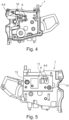
- 4 14 is an illustration of an internal view of the clamp module 1 viewed from a clamp side according to the present disclosure. In other words is in 4 a section through the clamping module 1 is shown. In this case, the printed circuit board is arranged on the side not facing the viewer and the cut is made in such a way that the optical window 10 can be seen.
- the clamping module 1 therefore shows the optical window 10, which consists of two plastic lenses and behind which the photodetector 8 and the first light source 4 and the second light source 6 are arranged.
- figure 5 14 is an illustration of an external view of the clamp module 1 viewed from the printed circuit board 11 side according to the present disclosure.
- the optical window 10 and the "recording" of the printed circuit board 11 for attachment to the clamping module 1 is shown schematically. That means, figure 5 is in contrast to 4 shown from the other side.
- the fastening means 13 are shown.
- the optical windows 10 or recesses can be seen, through which the light beams 5 and 6 of the first light source 4, the second light source 6 and the photodetector 8 are shown.
- the light sources 4 and 6 and the photodetector 8 are not shown directly, but only their position if the printed circuit board 11 is placed in the receptacle.
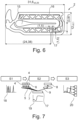
- the hose clamp 2 has a tapered elongated hole 15 through which an infusion hose runs.
- the infusion tube is not closed at one end of the elongated hole 15 and is compressed when it is passed to the other end of the Slot 15 is pushed.
- the hose clamp 2 is in an open state. In this state, the hose clamp 2 is pushed into the clamp module 1.
- the hook shown on tubing clamp 2 snaps into an eyelet on the front cover (at the same time a pump-side clamp is closed to prevent free flow).
- the front flap is opened, the hose clamp 2 pulls over the infusion hose and thus closes the passage.
- Reference number 16 relates here only to a reinforcement of the hose clamp 2 itself.
- the measuring point 17 is provided and designed to reflect the at least one first light beam 5 and the at least one second light beam 7 and to send the reflected light 9 back to the photodetector 8 .
- the total length displayed (31.6mm) corresponds to a total length for detecting that the hose clamp 2 is inserted into the clamping module.
- FIG. 12 is a block diagram representation of a color measurement and its implementation within an infusion pump, in accordance with the present disclosure.
- a first step S1 the sample or the measuring point 17 of the hose clamp 2 is sequentially illuminated.
- the sequential illumination results in illumination spectra as shown with reference numeral 18.
- the at least one first light beam 5 strikes in the colors red, green and blue, starting from of the first light source 4 and the second light beam 7, starting from the second light source 6, onto the measuring point 17.
- the measuring point 17 reflects in a step S2 and the reflected light 9 strikes the photodetector 8, which records the spectral properties of the material according to the reference number 19.
- a third step S3 a remission spectrum generates a photocurrent in the photodetector 8.
- the resulting signal is output in an evaluation spectrum according to reference number 20.
Landscapes
- Health & Medical Sciences (AREA)
- Heart & Thoracic Surgery (AREA)
- Animal Behavior & Ethology (AREA)
- General Health & Medical Sciences (AREA)
- Biomedical Technology (AREA)
- Engineering & Computer Science (AREA)
- Hematology (AREA)
- Life Sciences & Earth Sciences (AREA)
- Veterinary Medicine (AREA)
- Anesthesiology (AREA)
- Public Health (AREA)
- Vascular Medicine (AREA)
- Pulmonology (AREA)
- Physics & Mathematics (AREA)
- Fluid Mechanics (AREA)
- Infusion, Injection, And Reservoir Apparatuses (AREA)
Applications Claiming Priority (1)
| Application Number | Priority Date | Filing Date | Title |
|---|---|---|---|
| DE102021215067.5A DE102021215067A1 (de) | 2021-12-28 | 2021-12-28 | IV Systems - Infusionspumpe zur Erkennung der Farbe einer Schlauchklemme mit IR-Markern |
Publications (1)
| Publication Number | Publication Date |
|---|---|
| EP4205779A1 true EP4205779A1 (fr) | 2023-07-05 |
Family
ID=84604192
Family Applications (1)
| Application Number | Title | Priority Date | Filing Date |
|---|---|---|---|
| EP22216745.4A Pending EP4205779A1 (fr) | 2021-12-28 | 2022-12-27 | Pompe à perfusion de système iv pour détecter la couleur d'un collier de serrage de tuyau souple à l'aide de marqueurs ir |
Country Status (4)
| Country | Link |
|---|---|
| US (1) | US20230201557A1 (fr) |
| EP (1) | EP4205779A1 (fr) |
| CN (1) | CN116350880A (fr) |
| DE (1) | DE102021215067A1 (fr) |
Cited By (1)
| Publication number | Priority date | Publication date | Assignee | Title |
|---|---|---|---|---|
| EP4599863A1 (fr) | 2024-02-12 | 2025-08-13 | B. Braun Melsungen AG | Dispositif médical |
Families Citing this family (3)
| Publication number | Priority date | Publication date | Assignee | Title |
|---|---|---|---|---|
| DE102024121815A1 (de) * | 2024-07-31 | 2026-02-05 | B. Braun Melsungen Aktiengesellschaft | Medizinisches Überleitungssystem für eine medizinische Schlauchpumpe, medizinische Schlauchpumpe, und Verfahren für eine medizinische Schlauchpumpe |
| EP4710964A1 (fr) * | 2024-09-16 | 2026-03-18 | B. Braun Melsungen AG | Système de dérivation médicale pour pompe médicale, module de pince pour pompe médicale, pompe médicale et procédé de détection de système de dérivation médicale |
| EP4714487A1 (fr) | 2024-09-19 | 2026-03-25 | B. Braun Melsungen AG | Système de pompe à perfusion avec codage spectral |
Citations (4)
| Publication number | Priority date | Publication date | Assignee | Title |
|---|---|---|---|---|
| US5290239A (en) * | 1991-09-26 | 1994-03-01 | Baxter International, Inc. | Intravenous tube safety apparatus |
| US6635033B1 (en) * | 1998-10-12 | 2003-10-21 | B. Braun Medical, Inc. | Medical tubing slide clamp device for determining proper tubing size and functional characteristics |
| US20060224128A1 (en) | 2005-02-01 | 2006-10-05 | Kent Lurvey | Infusion delivery system |
| US9272129B2 (en) | 2007-06-21 | 2016-03-01 | Carefusion Corporation | Method for controlling drug delivery through an infusion set |
Family Cites Families (2)
| Publication number | Priority date | Publication date | Assignee | Title |
|---|---|---|---|---|
| CH690864A5 (de) | 1996-10-04 | 2001-02-15 | Hera Rotterdam Bv | Gerät und Verfahren zur Farbmessung und/oder Farberkennung sowie Vorrichtung in einem solchen Gerät. |
| CN108096665B (zh) | 2017-12-14 | 2019-12-03 | 南通大学 | 基于自适应多冗余判测的输液看护设备 |
-
2021
- 2021-12-28 DE DE102021215067.5A patent/DE102021215067A1/de active Pending
-
2022
- 2022-12-27 EP EP22216745.4A patent/EP4205779A1/fr active Pending
- 2022-12-27 US US18/088,922 patent/US20230201557A1/en active Pending
- 2022-12-28 CN CN202211700112.9A patent/CN116350880A/zh active Pending
Patent Citations (4)
| Publication number | Priority date | Publication date | Assignee | Title |
|---|---|---|---|---|
| US5290239A (en) * | 1991-09-26 | 1994-03-01 | Baxter International, Inc. | Intravenous tube safety apparatus |
| US6635033B1 (en) * | 1998-10-12 | 2003-10-21 | B. Braun Medical, Inc. | Medical tubing slide clamp device for determining proper tubing size and functional characteristics |
| US20060224128A1 (en) | 2005-02-01 | 2006-10-05 | Kent Lurvey | Infusion delivery system |
| US9272129B2 (en) | 2007-06-21 | 2016-03-01 | Carefusion Corporation | Method for controlling drug delivery through an infusion set |
Cited By (2)
| Publication number | Priority date | Publication date | Assignee | Title |
|---|---|---|---|---|
| EP4599863A1 (fr) | 2024-02-12 | 2025-08-13 | B. Braun Melsungen AG | Dispositif médical |
| WO2025172164A1 (fr) | 2024-02-12 | 2025-08-21 | B. Braun Melsungen Ag | Dispositif médical |
Also Published As
| Publication number | Publication date |
|---|---|
| CN116350880A (zh) | 2023-06-30 |
| US20230201557A1 (en) | 2023-06-29 |
| DE102021215067A1 (de) | 2023-06-29 |
Similar Documents
| Publication | Publication Date | Title |
|---|---|---|
| EP4205779A1 (fr) | Pompe à perfusion de système iv pour détecter la couleur d'un collier de serrage de tuyau souple à l'aide de marqueurs ir | |
| DE69735288T2 (de) | Flüssigkeitsanalysegerät mit Überprüfung der Schlauchanschlussarmatur | |
| WO2011072863A1 (fr) | Spectrodétecteur pour la vérification de documents de valeur | |
| EP1588209A1 (fr) | Dispositif et procede pour adapter la position d'un verre de lunettes a la position de la pupille | |
| EP1547026B1 (fr) | Dispositif et procede permettant de verifier l'authenticite d'une marque infalsifiable | |
| WO2000070547A1 (fr) | Dispositif d'identification de personnes | |
| DE102005050807B4 (de) | Vorrichtung zur Messung von Erhöhungen und/oder Vertiefungen einer Oberfläche | |
| EP4001854B1 (fr) | Capteur | |
| EP3570256B1 (fr) | Procédé de vérification et dispositif de lecture pour un marquage de sécurité | |
| EP4710964A1 (fr) | Système de dérivation médicale pour pompe médicale, module de pince pour pompe médicale, pompe médicale et procédé de détection de système de dérivation médicale | |
| DE112020001271B4 (de) | Verfahren und Vorrichtung zur Bestimmung der Oberflächenfarbe von zumindest teilweise lichtdurchlässigen Materialien | |
| DE69722230T2 (de) | Verfahren und einrichtung zur feststellung von pfandwertanzeigen | |
| DE102019117858B3 (de) | Prüfgerät und Verfahren zur Prüfung der Retroreflexion und/oder Fluoreszenz eines Objekts | |
| DE3239995A1 (de) | Vorrichtung zum erkennen von dokumenten | |
| DE10118329A1 (de) | Verfahren zur Qualitätsprüfung bzw. zur optischen Charakterisierung von Milch und deren Vorrichtung | |
| DE102021113233A1 (de) | Verfahren und Vorrichtung zum Inspizieren von Oberflächen | |
| DE60320355T2 (de) | Lesekopf für diffuse Reflektion | |
| EP2085154A2 (fr) | Procédé, dispositif d'éclairage et système de tri à base spectrale | |
| EP3446294B1 (fr) | Dispositif et procédé de surveillance de caractéristiques de sécurité en couleur | |
| EP0756698A1 (fr) | Systeme d'identification des couleurs a la surface d'objets | |
| EP2825868B1 (fr) | Système de test et procédé de contrôle de l'orientation d'une bandelette de test | |
| DE102011016509A1 (de) | Verfahren zur Prüfung von Wertdokumenten | |
| DE102022128033A1 (de) | Vorrichtung und Verfahren zum Messen optischer Eigenschaften, insbesondere Farbmessgerät | |
| DE19724252C2 (de) | Meßkopf zur Verwendung in einer Anordnung zur Bestimmung des Zeitpunktes eines Farbumschlags eines Indikators in einem Proberöhrchen für die Messung der thermischen Stabilität einer in dem Proberöhrchen befindlichen festen und aufheizbaren Probe, insbesondere von PVC | |
| AT4200U1 (de) | Vorrichtung und anlagen zur prüfung winkelabhängiger farben |
Legal Events
| Date | Code | Title | Description |
|---|---|---|---|
| PUAI | Public reference made under article 153(3) epc to a published international application that has entered the european phase |
Free format text: ORIGINAL CODE: 0009012 |
|
| STAA | Information on the status of an ep patent application or granted ep patent |
Free format text: STATUS: THE APPLICATION HAS BEEN PUBLISHED |
|
| AK | Designated contracting states |
Kind code of ref document: A1 Designated state(s): AL AT BE BG CH CY CZ DE DK EE ES FI FR GB GR HR HU IE IS IT LI LT LU LV MC ME MK MT NL NO PL PT RO RS SE SI SK SM TR |
|
| STAA | Information on the status of an ep patent application or granted ep patent |
Free format text: STATUS: REQUEST FOR EXAMINATION WAS MADE |
|
| 17P | Request for examination filed |
Effective date: 20240103 |
|
| RBV | Designated contracting states (corrected) |
Designated state(s): AL AT BE BG CH CY CZ DE DK EE ES FI FR GB GR HR HU IE IS IT LI LT LU LV MC ME MK MT NL NO PL PT RO RS SE SI SK SM TR |
|
| STAA | Information on the status of an ep patent application or granted ep patent |
Free format text: STATUS: EXAMINATION IS IN PROGRESS |
|
| 17Q | First examination report despatched |
Effective date: 20251110 |