EP4206402A1 - Système de branchement de transport ferroviaire - Google Patents
Système de branchement de transport ferroviaire Download PDFInfo
- Publication number
- EP4206402A1 EP4206402A1 EP21860177.1A EP21860177A EP4206402A1 EP 4206402 A1 EP4206402 A1 EP 4206402A1 EP 21860177 A EP21860177 A EP 21860177A EP 4206402 A1 EP4206402 A1 EP 4206402A1
- Authority
- EP
- European Patent Office
- Prior art keywords
- turnout
- compensation
- rail
- side frame
- traveling
- Prior art date
- Legal status (The legal status is an assumption and is not a legal conclusion. Google has not performed a legal analysis and makes no representation as to the accuracy of the status listed.)
- Granted
Links
Images


Classifications
-
- E—FIXED CONSTRUCTIONS
- E01—CONSTRUCTION OF ROADS, RAILWAYS, OR BRIDGES
- E01B—PERMANENT WAY; PERMANENT-WAY TOOLS; MACHINES FOR MAKING RAILWAYS OF ALL KINDS
- E01B25/00—Tracks for special kinds of railways
- E01B25/08—Tracks for mono-rails with centre of gravity of vehicle above the load-bearing rail
- E01B25/10—Mono-rails; Auxiliary balancing rails; Supports or connections for rails
-
- E—FIXED CONSTRUCTIONS
- E01—CONSTRUCTION OF ROADS, RAILWAYS, OR BRIDGES
- E01B—PERMANENT WAY; PERMANENT-WAY TOOLS; MACHINES FOR MAKING RAILWAYS OF ALL KINDS
- E01B25/00—Tracks for special kinds of railways
- E01B25/08—Tracks for mono-rails with centre of gravity of vehicle above the load-bearing rail
- E01B25/12—Switches; Crossings
-
- E—FIXED CONSTRUCTIONS
- E01—CONSTRUCTION OF ROADS, RAILWAYS, OR BRIDGES
- E01B—PERMANENT WAY; PERMANENT-WAY TOOLS; MACHINES FOR MAKING RAILWAYS OF ALL KINDS
- E01B25/00—Tracks for special kinds of railways
- E01B25/22—Tracks for railways with the vehicle suspended from rigid supporting rails
-
- E—FIXED CONSTRUCTIONS
- E01—CONSTRUCTION OF ROADS, RAILWAYS, OR BRIDGES
- E01B—PERMANENT WAY; PERMANENT-WAY TOOLS; MACHINES FOR MAKING RAILWAYS OF ALL KINDS
- E01B25/00—Tracks for special kinds of railways
- E01B25/22—Tracks for railways with the vehicle suspended from rigid supporting rails
- E01B25/26—Switches; Crossings
Definitions
- the present disclosure relates to the technical field of rail transit systems, and in particular, to a rail transit turnout system.
- the suspended monorail system is a kind of in-air rail transportation system. It has the advantages of good compatibility, high safety, high integration, low cost, flexible lines, environment friendly and low noise, etc. It meets the needs of modern urban rail transportation and is widely used in new type urban rail construction of China.
- the translational beam replacement type turnout completes line conversion between a straight traveling state and a curve traveling state by parallel movement of a branch rail beam and a curved rail beam.
- the segmental type turnout consists of a fixed beam, a driving beam and a driven beam, which makes the vehicle travel on a gently folding line approximate to an arc curve by mechanically driving the driving beam and the driven beam to be switched integrally using an electric motor mounted on the driving beam.
- the translational beam replacement type multi-way turnout has cumbersome structure, requires high strength of pier column and related mechanisms, and has disadvantages such as requiring high switching power, long switching time, poor in economy.
- the turnout beam is a multi-section broken-line beam, and there are many pier column foundations; at the same time, there are high requirement for the precision of the electric motor, and the reliability is poor.
- the present disclosure provides a rail transit turnout system to solve the problem that the translational beam replacement type multi-way turnout in the suspended rail transit system has cumbersome structure, requires high strength of pier column and related mechanisms, and has disadvantages such as requiring high switching power, long switching time, poor in economy and the problem that the turnout beam is a multi-section broken-line beam when the segmental type turnout is switched, and there are many pier column foundations; at the same time, there are high requirement for the precision of the electric motor, and the reliability is poor.
- the rail transit turnout system is charactered by comprising: a base rail beam fixedly supported by a plurality of base pier columns arranged at intervals; a turnout beam having a first end and a second end opposite to each other, wherein the first end of the turnout beam is provided on a first transition pier column and is rotatably connected to the first transition pier column through a center pin, the center pin is arranged vertically, and the second end of the turnout beam is provided on a second transition pier column and is capable of traveling on the second transition pier column; and branch rail beams, wherein there are at least two branch rail beams, the branch rail beams are fixedly supported by a plurality of branch pier columns arranged at intervals, each of the branch rail beams has a first end and a second end opposite to each other, the turnout beam is arranged between the base rail beam and the branch rail beams, the first end of the turnout beam docks with an end of the base rail beam facing the turnout beam, the second end
- the first transition pier column is provided with two compensation assemblies, the two compensation assemblies are oppositely disposed on two sides of the turnout beam, and each compensation assembly includes at least one compensation device, the compensation device has an output part, and the output part of the compensation device is operatively inserted into a gap between the first end of the turnout beam and the end of the base rail beam facing the turnout beam.
- the compensation device includes a compensation beam, wherein the compensation beam is the output part of the compensation device, and the compensation beam is operatively movable in a direction perpendicular to the base rail beam.
- the first transition pier column includes two opposite support columns, and an inner side of the support column is provided with a support seat corresponding to the compensation device;
- the compensation device includes a fixed seat and a driving unit, the fixed seat is fixedly disposed on the corresponding support seat, and a fixed end of the driving unit is fixedly disposed on the fixed seat, an output end of the driving unit is capable of telescopically moving back and forth along a horizontal direction, and the output end of the driving unit is fixedly connected with the compensation beam.
- the support seat is provided with a guide rail; and the bottom of the compensation beam is provided with a roller wheel, and the roller wheel is rollablely disposed on the guide rail.
- an inner side of the support column is provided with a guiding plate corresponding to the compensation device, and the bottom of the guiding plate is provided with a slide channel, and the top of the compensation beam is slidably disposed in the slide channel of the corresponding guiding plate.
- the system further includes a locking device, each compensation device is correspondingly configured with one locking device, and the locking device includes: a positioning seat fixedly disposed on the corresponding compensation beam and provided with a locking hole; a telescopic mechanism fixedly disposed on the first transition pier column; and a positioning pin, wherein the positioning pin has a first end and a second end opposite to each other, the first end of the positioning pin is fixedly connected to an output end of the telescopic mechanism, and the second end of the positioning pin is operatively inserted into the locking hole on the positioning seat.
- the second end of the turnout beam travels on the second transition pier column using a traveling mechanism
- the traveling mechanism includes: a traveling track, wherein the traveling track is arc-shaped, and a center of the arc-shaped traveling track is located on a central line of the center pin; and a traveling unit, wherein the second end of the turnout beam is connected to the traveling unit, and the traveling unit operatively travels on the traveling track.
- the traveling unit includes a first side frame and a second side frame arranged opposite to each other, an end of the first side frame and a corresponding end of the second side frame are connected by connecting beams, bottoms of the first side frame and the second side frame are respectively provided with installation grooves, and the second end of the turnout beam is sequentially fixedly connected in the installation grooves at the bottoms of the first side frame and the second side frame.
- the traveling unit further includes: a plurality of wheel shafts arranged at intervals and configured to connect tops of the first side frame and the second side frame, wherein one of the plurality of the wheel shafts is provided with a drive wheel, and the drive wheel is rollablely disposed on the traveling track; and a drive motor fixedly disposed on an outer side of the second side frame, wherein an output shaft of the drive motor is fixedly connected with the one of the plurality of wheel shafts.
- the first end of the turnout beam docks with the end of the base rail beam facing the turnout beam, the first end of the turnout beam is rotatably disposed on the first transition pier column, and the second end of the turnout beam operatively selects to dock with the first end of a certain branch rail beam, the purpose of switching can be achieved by operating the rotation of the first end of the turnout beam on the first transition pier column.
- the present disclosure adopts a piece of turnout beam as the main body of the turnout, which has a short length and can greatly reduce the mass of the multi-way turnout beam in the prior art, and at the same time the volume and mass of the pier column are reduced and the cost is reduced.
- the present disclosure Compared with the segment type multi-way turnout, the present disclosure has only one broken-line segment, and needs only two transition pier column beams, which has higher reliability and lower cost.
- the rail transit turnout system disclosed in the present disclosure is simple and reliable in operation, can effectively shorten the switching time, improves the transportation efficiency, and has good practical value.
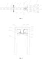
- FIG. 1 is a schematic structural diagram of a rail transit turnout system according to an embodiment of the present disclosure.
- the system includes a base rail beam 1, a turnout beam 5 and branch rail beams, wherein the base rail beam 1 is fixedly supported by a plurality of base pier column 2 arranged at intervals, and the turnout beam 5 has a first end and a second end opposite to each other.
- the first end of the turnout beam 5 is disposed on a first transition pier column 3, and the first end of the turnout beam 5 is rotatably connected to the first transition pier column 3 through a center pin 4 which is arranged vertically.
- the second end of the turnout beam 5 is disposed on a second transition pier column 6, and the second end of the turnout beam 5 can travel on the second transition pier column 6.
- the branch rail beams are fixedly supported by a plurality of branch pier columns 7 arranged at intervals, and each branch rail beam has a first end and a second end opposite to each other.
- the turnout beam 5 is arranged between the base rail beam 1 and the branch rail beams, the first end of the turnout beam 5 docks with an end of the base rail beam 1 facing the turnout beam 5, and the second end of the turnout beam 5 operatively selects to dock with the first end of a certain one of the branch rail beams.
- the second ends of the branch rail beams extend in a direction away from the turnout beam 5.
- the purpose of switching can be achieved by operating the rotation of the first end of the turnout beam 5 on the first transition pier column 3.
- the present disclosure adopts a piece of turnout beam as the main body of the turnout, which has a short length and can greatly reduce the mass of the multi-way turnout beam in the prior art, and at the same time the volume and mass of the pier column are reduced and the cost is reduced.
- the present disclosure has only one broken-line segment, and needs only two transition pier column beams, which has higher reliability and lower cost.
- the first branch rail beam 8 and the third branch rail beam 10 are respectively arranged on two sides of the second branch rail beam 9.
- the second branch rail beam 9 and the base rail beam 1 are positioned in a same line.
- the first branch rail beam 8, the second branch rail beam 9 and the third branch rail beam 10 are arranged in a fan shape.
- first ends of the plurality of branch rail beams can be fixedly supported by one branch pier column 7.
- the present disclosure provides a compensation assembly.
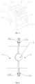
- FIG. 2 is a schematic structural diagram of the compensation assembly in FIG. 1 .
- the two compensation assemblies are oppositely arranged on two sides of the turnout beam 5.
- Each compensation assembly includes at least one compensation device 12.
- the compensation device 12 has an output part, and the output part of the compensation device 12 is operatively inserted into the gap between the first end of the turnout beam 5 and the end of the base rail beam 1 facing the turnout beam 5, so that the gap between the base rail beam 1 and the turnout beam 5 can be filled to ensure the reliability of the running of a rail vehicle across the base rail beam 1 and the turnout beam 5.
- the compensation device 12 includes a compensation beam 122, which is the output part of the compensation device, and the compensation beam 122 operatively moves in a direction perpendicular to the base rail beam 1.
- the first transition pier column 3 may include two opposite support columns 301.
- An inner side of the support column 301 is provided with a support seat 302 corresponding to the compensation device 12, and the compensation device 12 further includes a fixed seat 302 and a driving unit 125.
- the fixed seat 302 is secured on a corresponding support seat 302.
- a fixed end of the driving unit 125 is secured on the fixed seat 302, the output end of the driving unit 125 can be telescopically moved back and forth along a horizontal direction, and the output end of the driving unit 125 is fixedly connected to the compensation beam 122.
- the compensation beam 122 needs to compensate the gap between the base rail beam 1 and the turnout beam 5
- the output end of the driving unit 125 can drive the compensation beam 122 to move to implement the compensation.
- the driving unit 125 there can be two driving units 125 disposed opposite to each other in the horizontal direction, and the two driving units 125 move synchronously to make the compensation beam 122 move in a predetermined direction.
- the driving unit 125 may be a linear reciprocating motion mechanism such as an electric push rod, a hydraulic cylinder, etc., which is not limited in the present disclosure.
- the support seat 302 may be provided with a guide rail, and the bottom of the compensation beam 122 is provided with a roller wheel 128.
- the roller wheel 128 is rollable and disposed on the guide rail to reduce friction and improve the swiftness of the operation of the compensation beam 122.
- the bottom of the support seat 302 may be provided with a reinforcing plate 303, and the reinforcing plate 303 is connected with the support column 301 on the same side to improve the bearing capacity of the support seat 302.
- the inner side of the support column 301 is provided with a guiding plate 304 corresponding to the compensation device 12.
- the bottom of the guiding plate 304 is provided with a slide channel, and the top of the compensation beam 122 is slidably arranged in the slide channel of the corresponding guiding plate 304 to guide the movement of the compensation beam 122.
- the first transition pier column 3 also include a top beam 305 connecting the two opposite support columns 301 together, and a connection plate 306 is provided between the top of the guiding plate 304 and the top beam 305 to improve the reliability of installation of the guiding plate 304.
- each compensation device 12 is provided with one corresponding locking device.
- the locking device includes a positioning seat 126, a telescopic mechanism and a positioning pin 127.
- the positioning seat 126 is fixedly arranged on the corresponding compensation beam 122.
- the positioning seat 126 is provided with a locking hole.
- the telescopic mechanism is fixedly arranged on the first transition pier column 3.
- the positioning pin 127 has a first end and a second end opposite to each other.
- the first end of the positioning pin 127 is fixedly connected to the output end of the telescopic mechanism, and the second end of the positioning pin 127 is operatively inserted into the locking hole on the positioning seat 126.
- the telescopic mechanism is operated to move so that the second end of the positioning pin 127 is inserted into the locking hole on the positioning seat 126, and thus the compensation beam 122 can be locked.
- the positioning seat 126 is preferably arranged at the outer bottom of the compensation beam 122, and preferably there are two locking holes on the positioning seat 126, and the two positioning holes are respectively located on two sides of the compensation beam 122, so that the compensation beam 122 can be locked from two directions to improve the reliability of locking.
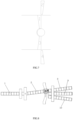
- FIG. 3 is a schematic diagram of the arrangement of the locking device in FIG. 2 .
- two telescopic mechanisms 1210 are provided inside the support seat 302, and the output ends of the two telescopic mechanisms 1210 are both vertically telescopic.
- the axial direction of the locking hole on the positioning seat 126 is vertical.
- the positioning pin 127 connected to the output end of the telescopic mechanism 1210 can be inserted into the locking hole on the positioning seat 126.
- the two telescopic mechanisms 1210 can also be arranged on the top of the support seat 302.
- the telescopic end of the telescopic mechanism 1210 moves in the horizontal direction, and the axial direction of the locking hole on the positioning seat 126 is in the horizontal direction.
- the positioning pin 127 connected to the output end of the telescopic mechanism 1210 can be inserted into the locking hole on the positioning seat 126.
- the output end of the telescopic mechanism is in a retracted state, so that the operation of the compensation beam 122 is not affected.
- a support plate 129 is provided on the inner side of the beam 122.
- the support plate 129 is used to support the traveling wheels of the rail vehicle to pass, and the inner side of the compensation beam 122 above the support plate 129 is used to support a guiding wheel of the rail vehicle to adapt to the smooth passage of the rail vehicle with the guiding wheel.
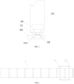
- FIG. 4 is a schematic assembly diagram of the turnout beam and the traveling mechanism
- FIG. 5 is a schematic structural diagram of the traveling mechanism.
- the traveling mechanism 11 includes a traveling track 117 and a traveling unit.
- the traveling track 117 is arc-shaped, and a center of the arc-shaped traveling track 117 is located on the center line of the center pin 4.
- the second end of the turnout beam 5 is connected to the traveling unit.
- the traveling unit can operatively travel on the traveling track 117, so that the first end of the turnout beam 5 is rotated by a certain angle around the center pin. That makes the turnout beam 5 connect with the branch rail beam of a branch to be guided, and then the key action of switching the turnout beam is completed.
- the traveling unit includes a first side frame 111 and a second side frame 115 arranged oppositely. An end of the first side frame 111 and a corresponding end of the second side frame 115 are connected by connecting beams 116. There are mounting grooves 118 provided on both sides of the bottom of the first side frame 111 and the second side frame 115, and the second end of the turnout beam 5 are fixedly connected in the mounting grooves 118 at the bottom of the first side frame 111 and the second side frame 115 in turn to realize the assembly of the second end of the turnout beam 5 and the traveling unit.
- the first side frame 111, the second side frame 115 and the connecting beam 11 constituting the traveling unit are preferably integrally formed, so that the traveling unit has sufficient bearing strength.
- the traveling unit further includes a drive motor 114 and a plurality of wheel shafts 113.
- the tops of the first side frame 111 and the top of the second side frame 115 are connected by the plurality of wheel shafts 113 arranged at intervals.
- One wheel shaft 113 among the plurality of wheel shafts 113 is provided with a drive wheel 119, and the remaining wheel shafts 113 of the plurality of wheel shafts 113 are provided with driven wheels 112. Both the drive wheel 119 and the driven wheels 112 are rollablely arranged on the traveling track 117.
- the drive motor 114 is fixedly disposed on the outside of the second side frame 115.
- the output shaft of the drive motor 114 is connected with the wheel shaft 113 on which the drive wheel 119 is mounted, so that the drive motor 114 can drive the wheel shaft 113 on which the drive wheel 119 is mounted to rotate, thereby driving the drive wheel 119 on the wheel shaft 113 to rotate on the traveling track 117 to realize the movement of the traveling unit on the traveling track 117, and the movement of the traveling unit can drive the plurality of driven wheels 112 to roll on the traveling track 117 to balance the movement of the traveling unit.
- the drive wheel 119 is located on a middle wheel shaft 113 among the plurality of wheel shafts 113, and the way of one drive wheel 119 cooperating with the plurality of driven wheels 112 can simplify the structure and optimize the space.
- each wheel shaft may also be provided with multiple wheels, so as to further improve the balance performance of the movement of the traveling unit, and the drive motor can rotate in forward and reverse directions to ensure that the turnout beam swings from side to side around the center rotating device upon switching.
- the drive motor is not the only way to drive.
- an electric push rod can be used to drive, or a slide rail can be mounted on the side of the turnout beam to cooperate with a rotating arm to drive, which is not limited in the present disclosure.
- the working principle of the rail transit turnout system is as follows: Switching process: Taking the three-way turnout as an example, it is assumed that an initial position of the turnout beam is a straight position as shown in the state in FIG. 1 , and an initial position of the compensation beam is all pulled out of the turnout beam, i.e., in a standby position.
- the compensation beam enters the gap between the turnout beam 5 and the base rail beam 1 to completely compensate it. At this time, the position of the compensation beam is a compensation position.
- the arrangement of the compensation beam is as shown in FIG 6 . Referring to FIG. 6 , there are four compensation beams, respectively, No. 1 compensation beam 121, No. 2 compensation beam 122, No. 3 compensation beam 123 and No.
- No. 1 compensation beam 121 and No. 2 compensation beam 122 are a group of compensation beams, and No. 3 compensation beam 123 and No. 4 compensation beam 124 are another group of compensation beams.
- the two groups of compensation beams are respectively located on two sides of the gap between the turnout beam 5 and the base rail beam 1.
- the compensation device, locking device, and traveling mechanism have their own control logic and can act independently, thus having the characteristics of automatic operation.
- the rail transit turnout system shown in the present disclosure is simple and reliable in operation, can effectively shorten the switching time, improve the transportation efficiency, and has good practical value.
Landscapes
- Engineering & Computer Science (AREA)
- Mechanical Engineering (AREA)
- Architecture (AREA)
- Civil Engineering (AREA)
- Structural Engineering (AREA)
- Railway Tracks (AREA)
- Train Traffic Observation, Control, And Security (AREA)
Applications Claiming Priority (2)
| Application Number | Priority Date | Filing Date | Title |
|---|---|---|---|
| CN202010893368.0A CN112127217B (zh) | 2020-08-31 | 2020-08-31 | 轨道交通道岔系统 |
| PCT/CN2021/112552 WO2022042338A1 (fr) | 2020-08-31 | 2021-08-13 | Système de branchement de transport ferroviaire |
Publications (3)
| Publication Number | Publication Date |
|---|---|
| EP4206402A1 true EP4206402A1 (fr) | 2023-07-05 |
| EP4206402A4 EP4206402A4 (fr) | 2024-10-09 |
| EP4206402B1 EP4206402B1 (fr) | 2025-07-30 |
Family
ID=73848717
Family Applications (1)
| Application Number | Title | Priority Date | Filing Date |
|---|---|---|---|
| EP21860177.1A Active EP4206402B1 (fr) | 2020-08-31 | 2021-08-13 | Système de branchement de transport ferroviaire |
Country Status (5)
| Country | Link |
|---|---|
| EP (1) | EP4206402B1 (fr) |
| JP (1) | JP7698666B2 (fr) |
| CN (1) | CN112127217B (fr) |
| AU (1) | AU2021334603B2 (fr) |
| WO (1) | WO2022042338A1 (fr) |
Families Citing this family (11)
| Publication number | Priority date | Publication date | Assignee | Title |
|---|---|---|---|---|
| CN110468636B (zh) * | 2019-08-30 | 2024-04-02 | 北京起重运输机械设计研究院有限公司 | 线路切换装置 |
| CN112127217B (zh) * | 2020-08-31 | 2022-03-01 | 中车长江车辆有限公司 | 轨道交通道岔系统 |
| CN112853822A (zh) * | 2021-03-16 | 2021-05-28 | 中国铁建重工集团股份有限公司 | 道岔组件和道岔组件的控制方法 |
| CN113062152B (zh) * | 2021-03-16 | 2022-02-11 | 中国铁建重工集团股份有限公司 | 道岔组件 |
| CN113353794B (zh) * | 2021-06-04 | 2022-06-24 | 中交二航局第二工程有限公司 | 一种可水平弯折的无缝连接轨道 |
| CN114013472B (zh) * | 2021-11-18 | 2025-02-28 | 中铁宝桥集团有限公司 | 一种悬挂式轨道单开车辆换线系统 |
| CN117188220A (zh) * | 2022-05-31 | 2023-12-08 | 比亚迪股份有限公司 | 道岔、渡线道岔和轨道交通系统 |
| CN117188221A (zh) * | 2022-05-31 | 2023-12-08 | 比亚迪股份有限公司 | 道岔和轨道交通系统 |
| CN115467195B (zh) * | 2022-10-26 | 2025-12-16 | 中车株洲车辆有限公司 | 一种补偿装置及道岔 |
| CN116552599A (zh) * | 2023-03-31 | 2023-08-08 | 中国铁建重工集团股份有限公司 | 磁浮道岔回转装置 |
| CN117107559B (zh) * | 2023-08-31 | 2025-10-28 | 羿鹏轨道交通开发(上海)有限公司 | 一种悬挂式单轨交通用道岔 |
Family Cites Families (16)
| Publication number | Priority date | Publication date | Assignee | Title |
|---|---|---|---|---|
| JPS549408U (fr) * | 1977-06-21 | 1979-01-22 | ||
| JPH04111801A (ja) * | 1990-08-31 | 1992-04-13 | H S S T:Kk | 桁式軌道用転てつ装置 |
| EP0829578A3 (fr) * | 1996-09-16 | 1998-05-13 | Wergles, Marx | Aiguillage pour installation monorail de manutention |
| DE102012002912A1 (de) * | 2012-02-14 | 2013-08-14 | Volkswagen Aktiengesellschaft | Fördervorrichtung |
| CN105040533B (zh) * | 2015-08-07 | 2017-04-19 | 中铁工程设计咨询集团有限公司 | 枢轴型道岔结构及道岔转辙的方法 |
| CN105839482B (zh) * | 2016-05-31 | 2017-06-30 | 西南石油大学 | 一种梁内悬挂式空列轨道道岔 |
| CN105951542B (zh) * | 2016-06-13 | 2017-11-03 | 陈刚 | 轨道变轨系统 |
| CN208530595U (zh) * | 2018-06-26 | 2019-02-22 | 比亚迪股份有限公司 | 内导向式道岔和具有其的轨道交通系统 |
| CN209307792U (zh) * | 2018-10-25 | 2019-08-27 | 中铁工程机械研究设计院有限公司 | 悬挂式单轨道岔摆动式补偿轨装置 |
| CN110714376A (zh) * | 2019-09-29 | 2020-01-21 | 深圳空铁科技股份有限公司 | 一种用于悬挂式轨道交通运输系统的道岔机构 |
| CN111172821A (zh) * | 2020-01-07 | 2020-05-19 | 中铁工程设计咨询集团有限公司 | 一种悬挂式单轨单轴单梁平转式道岔 |
| CN111139692B (zh) * | 2020-01-21 | 2024-07-12 | 曾鉴 | 一种轨道交通的轨道梁道岔机构 |
| CN111549588A (zh) * | 2020-05-09 | 2020-08-18 | 中国铁建重工集团股份有限公司 | 轨道系统 |
| CN111549587B (zh) * | 2020-05-09 | 2021-11-19 | 中国铁建重工集团股份有限公司 | 轨道系统 |
| CN112127217B (zh) * | 2020-08-31 | 2022-03-01 | 中车长江车辆有限公司 | 轨道交通道岔系统 |
| CN112127218B (zh) * | 2020-08-31 | 2022-03-25 | 中车长江车辆有限公司 | 补偿装置 |
-
2020
- 2020-08-31 CN CN202010893368.0A patent/CN112127217B/zh active Active
-
2021
- 2021-08-13 WO PCT/CN2021/112552 patent/WO2022042338A1/fr not_active Ceased
- 2021-08-13 EP EP21860177.1A patent/EP4206402B1/fr active Active
- 2021-08-13 AU AU2021334603A patent/AU2021334603B2/en active Active
- 2021-08-13 JP JP2022564535A patent/JP7698666B2/ja active Active
Also Published As
| Publication number | Publication date |
|---|---|
| CN112127217B (zh) | 2022-03-01 |
| WO2022042338A1 (fr) | 2022-03-03 |
| CN112127217A (zh) | 2020-12-25 |
| JP2023538168A (ja) | 2023-09-07 |
| EP4206402A4 (fr) | 2024-10-09 |
| JP7698666B2 (ja) | 2025-06-25 |
| AU2021334603A1 (en) | 2022-12-01 |
| AU2021334603B2 (en) | 2024-05-30 |
| EP4206402B1 (fr) | 2025-07-30 |
Similar Documents
| Publication | Publication Date | Title |
|---|---|---|
| EP4206402A1 (fr) | Système de branchement de transport ferroviaire | |
| CN112127218B (zh) | 补偿装置 | |
| CN108454651B (zh) | 跨座式单轨替换梁单渡线道岔设备 | |
| CN109895811B (zh) | 永磁式磁悬浮轨道系统及其道岔转向控制方法 | |
| JP2023538168A5 (fr) | ||
| CN110886160B (zh) | 基于双道岔结构的双线轨道梁和悬挂式空铁系统 | |
| CN208183445U (zh) | 单轨内导向式道岔和具有其的轨道交通系统 | |
| CN207469000U (zh) | 一种跨座式单轨升降型道岔 | |
| CN111535085A (zh) | 悬挂式单轨道岔 | |
| CN108589438B (zh) | 一种磁浮道岔 | |
| CN109898372B (zh) | 永磁式磁悬浮轨道交通的道岔系统及其控制方法 | |
| CN208183450U (zh) | 单轨内导向式道岔和具有其的轨道交通系统 | |
| CN207391948U (zh) | 一种液压驱动的升降型跨座式单轨道岔梁 | |
| CN209176672U (zh) | 一种单轨会车超车调度装置 | |
| CN111535084A (zh) | 非对称悬挂式单轨道岔 | |
| US3659529A (en) | Improved transportation system | |
| CN115506183A (zh) | 一种升降装置及道岔 | |
| US3902428A (en) | Tracked vehicle systems | |
| CN112429036B (zh) | 一种跨座式单轨同步换梁型道岔 | |
| WO2022105284A1 (fr) | Branchement à déplacement transversal à fond en creux | |
| CN110641517A (zh) | 内导向式道岔和具有其的轨道交通系统 | |
| CN217351959U (zh) | 空中列车自主导向装置及导向系统 | |
| CN112918503B (zh) | 一种轨道车辆及其轨道车辆滑台 | |
| CN219099696U (zh) | 单开道岔结构及单渡线道岔结构 | |
| CN212375640U (zh) | 道岔装置 |
Legal Events
| Date | Code | Title | Description |
|---|---|---|---|
| STAA | Information on the status of an ep patent application or granted ep patent |
Free format text: STATUS: THE INTERNATIONAL PUBLICATION HAS BEEN MADE |
|
| PUAI | Public reference made under article 153(3) epc to a published international application that has entered the european phase |
Free format text: ORIGINAL CODE: 0009012 |
|
| STAA | Information on the status of an ep patent application or granted ep patent |
Free format text: STATUS: REQUEST FOR EXAMINATION WAS MADE |
|
| 17P | Request for examination filed |
Effective date: 20230321 |
|
| AK | Designated contracting states |
Kind code of ref document: A1 Designated state(s): AL AT BE BG CH CY CZ DE DK EE ES FI FR GB GR HR HU IE IS IT LI LT LU LV MC MK MT NL NO PL PT RO RS SE SI SK SM TR |
|
| DAV | Request for validation of the european patent (deleted) | ||
| DAX | Request for extension of the european patent (deleted) | ||
| REG | Reference to a national code |
Ref country code: DE Ref legal event code: R079 Free format text: PREVIOUS MAIN CLASS: E01B0025100000 Ipc: E01B0025120000 Ref country code: DE Ref legal event code: R079 Ref document number: 602021035320 Country of ref document: DE Free format text: PREVIOUS MAIN CLASS: E01B0025100000 Ipc: E01B0025120000 |
|
| A4 | Supplementary search report drawn up and despatched |
Effective date: 20240905 |
|
| RIC1 | Information provided on ipc code assigned before grant |
Ipc: E01B 25/26 20060101ALI20240830BHEP Ipc: E01B 25/12 20060101AFI20240830BHEP |
|
| GRAP | Despatch of communication of intention to grant a patent |
Free format text: ORIGINAL CODE: EPIDOSNIGR1 |
|
| STAA | Information on the status of an ep patent application or granted ep patent |
Free format text: STATUS: GRANT OF PATENT IS INTENDED |
|
| INTG | Intention to grant announced |
Effective date: 20250317 |
|
| GRAS | Grant fee paid |
Free format text: ORIGINAL CODE: EPIDOSNIGR3 |
|
| GRAA | (expected) grant |
Free format text: ORIGINAL CODE: 0009210 |
|
| STAA | Information on the status of an ep patent application or granted ep patent |
Free format text: STATUS: THE PATENT HAS BEEN GRANTED |
|
| AK | Designated contracting states |
Kind code of ref document: B1 Designated state(s): AL AT BE BG CH CY CZ DE DK EE ES FI FR GB GR HR HU IE IS IT LI LT LU LV MC MK MT NL NO PL PT RO RS SE SI SK SM TR |
|
| REG | Reference to a national code |
Ref country code: GB Ref legal event code: FG4D |
|
| REG | Reference to a national code |
Ref country code: CH Ref legal event code: EP |
|
| REG | Reference to a national code |
Ref country code: DE Ref legal event code: R096 Ref document number: 602021035320 Country of ref document: DE |
|
| REG | Reference to a national code |
Ref country code: IE Ref legal event code: FG4D |
|
| REG | Reference to a national code |
Ref country code: NL Ref legal event code: FP |
|
| PGFP | Annual fee paid to national office [announced via postgrant information from national office to epo] |
Ref country code: NL Payment date: 20250730 Year of fee payment: 5 |
|
| PGFP | Annual fee paid to national office [announced via postgrant information from national office to epo] |
Ref country code: DE Payment date: 20250730 Year of fee payment: 5 |
|
| PGFP | Annual fee paid to national office [announced via postgrant information from national office to epo] |
Ref country code: GB Payment date: 20250730 Year of fee payment: 5 |
|
| PGFP | Annual fee paid to national office [announced via postgrant information from national office to epo] |
Ref country code: FR Payment date: 20250730 Year of fee payment: 5 Ref country code: AT Payment date: 20251020 Year of fee payment: 5 |
|
| PGFP | Annual fee paid to national office [announced via postgrant information from national office to epo] |
Ref country code: CH Payment date: 20250901 Year of fee payment: 5 |
|
| REG | Reference to a national code |
Ref country code: AT Ref legal event code: MK05 Ref document number: 1819041 Country of ref document: AT Kind code of ref document: T Effective date: 20250730 |
|
| PG25 | Lapsed in a contracting state [announced via postgrant information from national office to epo] |
Ref country code: PT Free format text: LAPSE BECAUSE OF FAILURE TO SUBMIT A TRANSLATION OF THE DESCRIPTION OR TO PAY THE FEE WITHIN THE PRESCRIBED TIME-LIMIT Effective date: 20251202 |
|
| PG25 | Lapsed in a contracting state [announced via postgrant information from national office to epo] |
Ref country code: IS Free format text: LAPSE BECAUSE OF FAILURE TO SUBMIT A TRANSLATION OF THE DESCRIPTION OR TO PAY THE FEE WITHIN THE PRESCRIBED TIME-LIMIT Effective date: 20251130 |
|
| PG25 | Lapsed in a contracting state [announced via postgrant information from national office to epo] |
Ref country code: NO Free format text: LAPSE BECAUSE OF FAILURE TO SUBMIT A TRANSLATION OF THE DESCRIPTION OR TO PAY THE FEE WITHIN THE PRESCRIBED TIME-LIMIT Effective date: 20251030 |
|
| REG | Reference to a national code |
Ref country code: LT Ref legal event code: MG9D |
|
| PG25 | Lapsed in a contracting state [announced via postgrant information from national office to epo] |
Ref country code: AT Free format text: LAPSE BECAUSE OF FAILURE TO SUBMIT A TRANSLATION OF THE DESCRIPTION OR TO PAY THE FEE WITHIN THE PRESCRIBED TIME-LIMIT Effective date: 20250730 |
|
| PG25 | Lapsed in a contracting state [announced via postgrant information from national office to epo] |
Ref country code: FI Free format text: LAPSE BECAUSE OF FAILURE TO SUBMIT A TRANSLATION OF THE DESCRIPTION OR TO PAY THE FEE WITHIN THE PRESCRIBED TIME-LIMIT Effective date: 20250730 |
|
| PG25 | Lapsed in a contracting state [announced via postgrant information from national office to epo] |
Ref country code: HR Free format text: LAPSE BECAUSE OF FAILURE TO SUBMIT A TRANSLATION OF THE DESCRIPTION OR TO PAY THE FEE WITHIN THE PRESCRIBED TIME-LIMIT Effective date: 20250730 |
|
| PG25 | Lapsed in a contracting state [announced via postgrant information from national office to epo] |
Ref country code: GR Free format text: LAPSE BECAUSE OF FAILURE TO SUBMIT A TRANSLATION OF THE DESCRIPTION OR TO PAY THE FEE WITHIN THE PRESCRIBED TIME-LIMIT Effective date: 20251031 |
|
| PG25 | Lapsed in a contracting state [announced via postgrant information from national office to epo] |
Ref country code: SE Free format text: LAPSE BECAUSE OF FAILURE TO SUBMIT A TRANSLATION OF THE DESCRIPTION OR TO PAY THE FEE WITHIN THE PRESCRIBED TIME-LIMIT Effective date: 20250730 |
|
| PG25 | Lapsed in a contracting state [announced via postgrant information from national office to epo] |
Ref country code: LV Free format text: LAPSE BECAUSE OF FAILURE TO SUBMIT A TRANSLATION OF THE DESCRIPTION OR TO PAY THE FEE WITHIN THE PRESCRIBED TIME-LIMIT Effective date: 20250730 |
|
| PG25 | Lapsed in a contracting state [announced via postgrant information from national office to epo] |
Ref country code: PL Free format text: LAPSE BECAUSE OF FAILURE TO SUBMIT A TRANSLATION OF THE DESCRIPTION OR TO PAY THE FEE WITHIN THE PRESCRIBED TIME-LIMIT Effective date: 20250730 Ref country code: BG Free format text: LAPSE BECAUSE OF FAILURE TO SUBMIT A TRANSLATION OF THE DESCRIPTION OR TO PAY THE FEE WITHIN THE PRESCRIBED TIME-LIMIT Effective date: 20250730 |
|
| PG25 | Lapsed in a contracting state [announced via postgrant information from national office to epo] |
Ref country code: RS Free format text: LAPSE BECAUSE OF FAILURE TO SUBMIT A TRANSLATION OF THE DESCRIPTION OR TO PAY THE FEE WITHIN THE PRESCRIBED TIME-LIMIT Effective date: 20251030 |
|
| PG25 | Lapsed in a contracting state [announced via postgrant information from national office to epo] |
Ref country code: ES Free format text: LAPSE BECAUSE OF FAILURE TO SUBMIT A TRANSLATION OF THE DESCRIPTION OR TO PAY THE FEE WITHIN THE PRESCRIBED TIME-LIMIT Effective date: 20250730 |
|
| PG25 | Lapsed in a contracting state [announced via postgrant information from national office to epo] |
Ref country code: RO Free format text: LAPSE BECAUSE OF FAILURE TO SUBMIT A TRANSLATION OF THE DESCRIPTION OR TO PAY THE FEE WITHIN THE PRESCRIBED TIME-LIMIT Effective date: 20250730 |
|
| PG25 | Lapsed in a contracting state [announced via postgrant information from national office to epo] |
Ref country code: SM Free format text: LAPSE BECAUSE OF FAILURE TO SUBMIT A TRANSLATION OF THE DESCRIPTION OR TO PAY THE FEE WITHIN THE PRESCRIBED TIME-LIMIT Effective date: 20250730 |
|
| PG25 | Lapsed in a contracting state [announced via postgrant information from national office to epo] |
Ref country code: DK Free format text: LAPSE BECAUSE OF FAILURE TO SUBMIT A TRANSLATION OF THE DESCRIPTION OR TO PAY THE FEE WITHIN THE PRESCRIBED TIME-LIMIT Effective date: 20250730 |
|
| PG25 | Lapsed in a contracting state [announced via postgrant information from national office to epo] |
Ref country code: LU Free format text: LAPSE BECAUSE OF NON-PAYMENT OF DUE FEES Effective date: 20250813 Ref country code: IT Free format text: LAPSE BECAUSE OF FAILURE TO SUBMIT A TRANSLATION OF THE DESCRIPTION OR TO PAY THE FEE WITHIN THE PRESCRIBED TIME-LIMIT Effective date: 20250730 |
|
| PG25 | Lapsed in a contracting state [announced via postgrant information from national office to epo] |
Ref country code: CZ Free format text: LAPSE BECAUSE OF FAILURE TO SUBMIT A TRANSLATION OF THE DESCRIPTION OR TO PAY THE FEE WITHIN THE PRESCRIBED TIME-LIMIT Effective date: 20250730 |
|
| PG25 | Lapsed in a contracting state [announced via postgrant information from national office to epo] |
Ref country code: SK Free format text: LAPSE BECAUSE OF FAILURE TO SUBMIT A TRANSLATION OF THE DESCRIPTION OR TO PAY THE FEE WITHIN THE PRESCRIBED TIME-LIMIT Effective date: 20250730 Ref country code: EE Free format text: LAPSE BECAUSE OF FAILURE TO SUBMIT A TRANSLATION OF THE DESCRIPTION OR TO PAY THE FEE WITHIN THE PRESCRIBED TIME-LIMIT Effective date: 20250730 |