EP4206814A1 - Dispositif d'inspection des tuyaux et de canalisation - Google Patents
Dispositif d'inspection des tuyaux et de canalisation Download PDFInfo
- Publication number
- EP4206814A1 EP4206814A1 EP21218234.9A EP21218234A EP4206814A1 EP 4206814 A1 EP4206814 A1 EP 4206814A1 EP 21218234 A EP21218234 A EP 21218234A EP 4206814 A1 EP4206814 A1 EP 4206814A1
- Authority
- EP
- European Patent Office
- Prior art keywords
- pipe
- probe
- camera
- duct
- tof sensor
- Prior art date
- Legal status (The legal status is an assumption and is not a legal conclusion. Google has not performed a legal analysis and makes no representation as to the accuracy of the status listed.)
- Granted
Links
Images


Classifications
-
- G—PHYSICS
- G03—PHOTOGRAPHY; CINEMATOGRAPHY; ANALOGOUS TECHNIQUES USING WAVES OTHER THAN OPTICAL WAVES; ELECTROGRAPHY; HOLOGRAPHY
- G03B—APPARATUS OR ARRANGEMENTS FOR TAKING PHOTOGRAPHS OR FOR PROJECTING OR VIEWING THEM; APPARATUS OR ARRANGEMENTS EMPLOYING ANALOGOUS TECHNIQUES USING WAVES OTHER THAN OPTICAL WAVES; ACCESSORIES THEREFOR
- G03B3/00—Focusing arrangements of general interest for cameras, projectors or printers
- G03B3/10—Power-operated focusing
- G03B3/12—Power-operated focusing adapted for remote control
-
- B—PERFORMING OPERATIONS; TRANSPORTING
- B08—CLEANING
- B08B—CLEANING IN GENERAL; PREVENTION OF FOULING IN GENERAL
- B08B9/00—Cleaning hollow articles by methods or apparatus specially adapted thereto
- B08B9/02—Cleaning pipes or tubes or systems of pipes or tubes
- B08B9/027—Cleaning the internal surfaces; Removal of blockages
- B08B9/04—Cleaning the internal surfaces; Removal of blockages using cleaning devices introduced into and moved along the pipes
- B08B9/049—Cleaning the internal surfaces; Removal of blockages using cleaning devices introduced into and moved along the pipes having self-contained propelling means for moving the cleaning devices along the pipes, i.e. self-propelled
-
- B—PERFORMING OPERATIONS; TRANSPORTING
- B08—CLEANING
- B08B—CLEANING IN GENERAL; PREVENTION OF FOULING IN GENERAL
- B08B9/00—Cleaning hollow articles by methods or apparatus specially adapted thereto
- B08B9/02—Cleaning pipes or tubes or systems of pipes or tubes
- B08B9/027—Cleaning the internal surfaces; Removal of blockages
- B08B9/04—Cleaning the internal surfaces; Removal of blockages using cleaning devices introduced into and moved along the pipes
- B08B9/049—Cleaning the internal surfaces; Removal of blockages using cleaning devices introduced into and moved along the pipes having self-contained propelling means for moving the cleaning devices along the pipes, i.e. self-propelled
- B08B9/0495—Nozzles propelled by fluid jets
-
- E—FIXED CONSTRUCTIONS
- E03—WATER SUPPLY; SEWERAGE
- E03F—SEWERS; CESSPOOLS
- E03F7/00—Other installations or implements for operating sewer systems, e.g. for preventing or indicating stoppage; Emptying cesspools
- E03F7/12—Installations enabling inspection personnel to drive along sewer canals
-
- E—FIXED CONSTRUCTIONS
- E03—WATER SUPPLY; SEWERAGE
- E03F—SEWERS; CESSPOOLS
- E03F9/00—Arrangements or fixed installations methods or devices for cleaning or clearing sewer pipes, e.g. by flushing
-
- F—MECHANICAL ENGINEERING; LIGHTING; HEATING; WEAPONS; BLASTING
- F16—ENGINEERING ELEMENTS AND UNITS; GENERAL MEASURES FOR PRODUCING AND MAINTAINING EFFECTIVE FUNCTIONING OF MACHINES OR INSTALLATIONS; THERMAL INSULATION IN GENERAL
- F16L—PIPES; JOINTS OR FITTINGS FOR PIPES; SUPPORTS FOR PIPES, CABLES OR PROTECTIVE TUBING; MEANS FOR THERMAL INSULATION IN GENERAL
- F16L55/00—Devices or appurtenances for use in, or in connection with, pipes or pipe systems
- F16L55/26—Pigs or moles, i.e. devices movable in a pipe or conduit with or without self-contained propulsion means
- F16L55/28—Constructional aspects
-
- G—PHYSICS
- G01—MEASURING; TESTING
- G01B—MEASURING LENGTH, THICKNESS OR SIMILAR LINEAR DIMENSIONS; MEASURING ANGLES; MEASURING AREAS; MEASURING IRREGULARITIES OF SURFACES OR CONTOURS
- G01B11/00—Measuring arrangements characterised by the use of optical techniques
- G01B11/08—Measuring arrangements characterised by the use of optical techniques for measuring diameters
- G01B11/12—Measuring arrangements characterised by the use of optical techniques for measuring diameters internal diameters
-
- G—PHYSICS
- G01—MEASURING; TESTING
- G01B—MEASURING LENGTH, THICKNESS OR SIMILAR LINEAR DIMENSIONS; MEASURING ANGLES; MEASURING AREAS; MEASURING IRREGULARITIES OF SURFACES OR CONTOURS
- G01B11/00—Measuring arrangements characterised by the use of optical techniques
- G01B11/24—Measuring arrangements characterised by the use of optical techniques for measuring contours or curvatures
-
- F—MECHANICAL ENGINEERING; LIGHTING; HEATING; WEAPONS; BLASTING
- F16—ENGINEERING ELEMENTS AND UNITS; GENERAL MEASURES FOR PRODUCING AND MAINTAINING EFFECTIVE FUNCTIONING OF MACHINES OR INSTALLATIONS; THERMAL INSULATION IN GENERAL
- F16L—PIPES; JOINTS OR FITTINGS FOR PIPES; SUPPORTS FOR PIPES, CABLES OR PROTECTIVE TUBING; MEANS FOR THERMAL INSULATION IN GENERAL
- F16L2101/00—Uses or applications of pigs or moles
- F16L2101/10—Treating the inside of pipes
- F16L2101/12—Cleaning
-
- F—MECHANICAL ENGINEERING; LIGHTING; HEATING; WEAPONS; BLASTING
- F16—ENGINEERING ELEMENTS AND UNITS; GENERAL MEASURES FOR PRODUCING AND MAINTAINING EFFECTIVE FUNCTIONING OF MACHINES OR INSTALLATIONS; THERMAL INSULATION IN GENERAL
- F16L—PIPES; JOINTS OR FITTINGS FOR PIPES; SUPPORTS FOR PIPES, CABLES OR PROTECTIVE TUBING; MEANS FOR THERMAL INSULATION IN GENERAL
- F16L2101/00—Uses or applications of pigs or moles
- F16L2101/30—Inspecting, measuring or testing
Definitions
- the invention relates to a device and a method for inspecting and/or cleaning pipes and/or ducts.
- Sewage pipes and sewers can have a round, egg-shaped, jaw-shaped, channel-shaped or even a rectangular or square cross-section.
- the cross-section can have very different, additional dimensions and can also change from one section to another in a pipe or sewer system to be inspected .
- a common light source is LED lamps.
- devices for the inspection and/or cleaning of pipes and/or ducts, devices are used which have powered probes that provide a video signal to their users via a cable and optionally have a carriage. Users can also send wired control signals to the device and coordinate the inspection.
- Cameras for example, are imaging means for providing the video signal.
- Most approaches use a drivable lens, such as a motorized focuser or a liquid lens.
- the controllable lenses are used in combination with a control unit, which specifies and sets the focus.
- EP 2 975 455 A1 For example, an optical distance measuring device is known which is aligned parallel to a camera which has a liquid lens. The optical distance measuring device enables focusing on objects that are in front of the camera in a straight line direction.
- EP 2 975 455 A1 not resolved is focusing on long tubes and ducts. In the case of long pipes or ducts, it is often no longer possible to measure the reflection, so that the focussing fails.
- the object of the invention is to provide a device and a method for inspecting and/or cleaning pipes and/or ducts, which has advantageous focusing behavior, robust behavior and can be used with different pipe and duct diameters. Furthermore, advantageous illumination behavior, in particular uniform illumination of the pipe or duct section to be inspected, is important in order not to overlay the camera and to enable sufficient contrast and sharpness of the video signal.
- a device for inspecting and/or cleaning pipes and/or ducts comprising a probe and at least one measuring device for measuring a pipe or duct geometry and for measuring a distance of the probe from an object located in the pipe or duct
- the probe is equipped with at least one camera and the measuring device is coupled to a control device.
- the measuring device is equipped with at least one TOF sensor, and the control device is set up to adjust a focusing unit of the camera coupled to the control device and/or an illumination unit based on measurement data from the TOF sensor.
- the invention provides for the use of a TOF (time-of-flight) sensor, using the measurement data from which the pipe or duct geometry can be determined and, for example, a pipe diameter can be derived.
- the TOF sensor measures distances to any objects in the pipe or duct.
- the arrangement and detection range of the TOF sensor are chosen so that both the pipe or duct wall and any objects located in the pipe or duct can be detected.
- the TOF sensor can be embodied as a TOF camera with a 3D camera system, which can measure distances using a time-of-flight (TOF) method.
- the distance to the imaged object is determined for each pixel in the TOF sensor's detection range.
- the TOF sensor includes a light emitting unit, for example LEDs or laser diodes, and a receiving unit with optics, which collects the light reflected from the environment and images the environment on an image sensor.
- suitable control electronics which are known per se, not only the intensity of the light but also the propagation time of the light is determined for each pixel, as a result of which distance data are available for each pixel of the image sensor.
- the TOF sensor is thus able to simultaneously measure both the pipe geometry and the distance from the probe to an object located in the pipe.
- the measuring speeds of the TOF sensor which reach up to 500 or 1000 frames per second and thus provide information in real time, are particularly advantageous.
- a desired focus distance can be determined either by a lookup table or a formula in the control device, to which the camera can be set or is set if no object is identified in the pipe. If, for example, a new pipe section is detected where the pipe geometry changes, the control device can ideally detect this in real time and output a new, desired focal distance. Thus, the device is able to traverse and inspect pipe systems with different and varying pipe diameters.
- Optics in particular lenses, can expediently be installed both in front of the transmitting part and in front of the receiving part of the TOF sensor in order to optimally coordinate the detection range of the TOF sensor for detecting the pipe geometry and for detecting objects located in the pipe.
- the optics are preferably controllable so that the viewing angle of the TOF sensor can be adjusted accordingly.
- the viewing angle of the TOF sensor is preferably between 50° and 90°, in particular in the range from 65° to 75°.
- the video signal is preferably transmitted via copper cables and corresponding signal converter elements, which are known from the prior art.
- the system is therefore more robust than fiber optic based systems, as the bending resistance of copper cables is generally higher than that of fiber optic cables.
- the TOF sensor can be located either in the chassis or preferably in the camera head.
- the measurement range of the TOF sensor is preferably in the camera's field of view, which makes it easier for the user to establish a connection between the measurement data of the TOF sensor and the video image.
- the TOF sensor can be aligned in particular at an angle inclined to an optical axis of a lens arranged in front of the camera.
- the camera can be mounted non-rotatably on the probe.
- the camera is mounted on the probe such that it can be rotated or pivoted about a first axis of rotation that is perpendicular to a main axis of the probe.
- the control device can rotate the camera head about the first axis of rotation depending on the determined pipe geometry.
- the ability of the camera to rotate or pivot about the first axis of rotation can be used to angle the camera in the direction of a pipe wall, so that the viewing angle of the camera captures an area of a pipe wall more closely.
- the camera can be mounted on the probe such that it can be rotated or pivoted about a second axis of rotation running in the main axis of the probe.
- the control device can rotate the camera head about the second axis of rotation. The ability to rotate or swivel the camera around the second axis of rotation is advantageous in order to align the camera image horizontally, regardless of the position and orientation of the probe in the pipe, so that a user is able to correctly identify the top, bottom, left and right of the image .
- the present invention manages to minimize the installation space, the complexity and the susceptibility to errors of the pipe inspection system, in particular by means of a camera head that can be rotated or pivoted about the horizontal axis. Tilting the camera makes it possible to provide usable images from adequate perspectives with different pipe diameters.
- the tilting angle can be controlled by the control device depending on the tube geometry.
- a device is particularly advantageous whose camera is mounted on the probe such that it can be rotated or pivoted both about the first axis of rotation and about the second axis of rotation.
- the position of the first axis of rotation in space can be fixed by means of rotation about the second axis of rotation.
- the first axis of rotation can be aligned vertically, for example. This makes it possible for the camera to be aligned, for example, in lateral branches of the pipe in order to enable an inspection.
- the first axis of rotation can be oriented horizontally to angle the camera up or down. In the typical case when the probe is not in the middle of the pipe, but below it due to a large pipe diameter, the camera can be angled upwards so that both the lower pipe wall and the upper pipe wall can be evenly illuminated and inspected.
- the device does not necessarily require additional sensors in order to determine a distance between the probe and the pipe wall.
- the TOF sensor enables the simultaneous detection of the pipe wall and objects located in the pipe.
- the device nevertheless comprises at least one further distance measuring device, which comprises a further TOF sensor and/or a capacitive or optical sensor, preferably a large number of TOF sensors arranged in a ring around a main axis of the probe, the control device being set up in order to adjust the focusing unit and/or the lighting unit also on the basis of measurement data determined by the further distance measuring device.
- the device can therefore include one or more TOF sensors, and additionally one or more other, in particular capacitive or optical, distance measuring sensors.
- the further distance measuring device can also include one or more "simple" TOF sensors which do not provide a 3D image but merely record and output a distance of the sensor from an object in the direction of the light pulse emitted by the TOF in the form of a numerical value.
- the first distance measuring device is arranged on a non-rotatably mounted part of the device and the second distance measuring device is arranged on a rotatably mounted part of the device, or vice versa.
- the Further measurement data can advantageously be used to check the plausibility of measurement results from the first TOF sensor, in the case of multiple TOF sensors in particular to create a so-called image stack of the environment and/or to obtain a true-to-the-original 3D image of the pipe to be inspected.
- the focusing unit includes at least one mechanically and/or magnetically adjustable lens or a liquid lens for adjusting the focus.
- an illumination unit is preferably used in the TOF sensor, which emits light in a part of the electromagnetic spectrum that is different from an illumination unit of the camera.
- the lighting unit of the camera uses light in the visible range with a wavelength of 400 nm to 700 nm and the lighting unit of the TOF sensor uses light in the infrared range with a wavelength of more than 700 nm, in particular from 780 to 3000 nm.
- the lighting unit comprises one or more light sources and the control device is set up to selectively adjust the brightness of the light source or light sources individually or in groups based on the measurement data of the TOF sensor and/or the light source or light sources individually or on and off in groups based on the measurement data of the TOF sensor.
- the device comprises a plurality of light sources, which can be arranged on the probe, for example but not restrictively, in a ring around the camera.
- Individual light sources or groups of light sources can be dimmed or brightened to control the brightness of the pipe segments facing them in the camera image. This serves the purpose of adaptively illuminating the area around the pipe.
- a balanced illumination of the surroundings captured by the camera allows an improvement in the contrast and sharpness of the video image.
- the pipe is often well illuminated due to symmetry. If all light sources were to shine with the same intensity, this would have the result, for example if the camera was not centered in the pipe, that one half of the pipe that was further away would be illuminated too weakly, while a half of the pipe that was close would be illuminated too strongly and the camera would fade, so that the camera shutter reacts and the entire picture becomes too dark.
- the control device can be set up to switch ring segments with a plurality of light sources on and off or to brighten or dim them.
- a first group of light sources can be provided for illuminating a close range and a second group of light sources for illuminating a far range.
- the groups can differ in terms of upstream beam-shaping optics, with scattering optics, e.g. using concave lenses, being upstream in the close-up range in order to generate diffuse light, and no or focusing optics, e.g. using convex lenses, being upstream in the long-distance range. If the focus is on the near range, the second group of light sources for illuminating the far range can be switched off. If the focus is on the long range, then the first group of light sources for illuminating the close range can be switched off.
- the control device can be set up to adaptively adjust the beam shaping optics of the light from the light sources.
- LEDs Common light sources for close range are LEDs. In the far range, LEDs, but also laser light, e.g. from laser diodes, can be used, especially in combination with LEDs.
- the plurality of light sources for example LEDs or laser devices such as laser diodes, which can be driven individually or in groups, are preferably arranged on the probe.
- the light source or light sources are particularly preferably mounted on the probe such that they can be rotated and/or pivoted.
- the control device is set up to spatially align the light cone of the light source or light sources. The control device can thus control the light sources for balanced illumination depending on the tube geometry and the viewing angle of the camera head.
- Controlling the angle of the camera head and controlling the LEDs can also be done through lookup tables or through formulas.
- a control circuit can advantageously be used to control the LEDs, since the brightness of the image depends, for example, on the optical properties of the tube walls and the impurities in the tube.
- the probe is mounted on an inspection vehicle to move the probe through the pipe.
- the TOF sensor is arranged, for example, on a chassis of the inspection vehicle or on the probe.
- a lifting arm, known per se, on which the probe is arranged, can optionally be provided in the inspection vehicle.
- the lift arm is preferably height adjustable by the controller to navigate the sonde at or near the center of the pipe.
- the probe is mounted on a flexible eel insertable into the pipe for pushing the probe through the pipe.
- the TOF sensor is arranged on the probe.
- provision can be made for distributing the sensors on a part of the probe that is not rotatably mounted and/or on a part of the probe that is only rotatably mounted once and/or on a part of the probe that is rotatably mounted twice.
- the probe is arranged on a high-pressure hose that can be inserted into the pipe or duct and is designed as a line for a pressure medium, with the high-pressure hose and/or the probe being equipped with nozzles on its circumference, which are controlled by valves are controlled in fluid communication with a fluid line to advance the probe through the pipe.
- the probe is equipped with further nozzles for navigation in the pipe or channel.
- a fluid such as water or compressed air is preferably used as the pressure medium.
- a sliding eel can additionally be provided in order to push the probe through the pipe. While the sliding eel is designed to be rigid with a fiberglass core, for example, the high-pressure hose can be designed to be more flexible.
- the nozzles are preferably arranged behind the camera in the feed direction.
- the probe is located off-center of the pipe, so that the invention provides the user with particular advantages as described above.
- the probe equipped with the camera is inserted into a pipe and the focusing unit of the camera is controlled using the measurement data from the TOF sensor, so that when the TOF sensor detects an object in the pipe, the focus of the camera is set to the object or is adjustable to the object and the focus of the camera is adjusted to an area on a pipe wall or is adjustable when the TOF sensor does not detect an object located in the pipe.
- the lighting unit is controlled using the measurement data from the TOF sensor.
- the device can be equipped with a kind of autofocus system in which the focus is always set on the object located in the pipe, if present, and always set on a region of the pipe wall if no object is present in the pipe.
- the user is offered an interface to focus the camera on an object located in the pipe or alternatively to focus on the area on the pipe wall. Provision can be made for the user to be able to manually readjust a proposed focus.
- image processing software can be used which graphically highlights focusable detected objects located in the pipe and/or a focusable area of the pipe wall on the video image for the user.
- a distance between the probe and the pipe wall is preferably determined from the measurement data from the TOF sensor, specifically using extrapolation of the measurement data from the TOF sensor, for example assuming a uniform pipe diameter.
- a pipe diameter and/or a category of the pipe cross section as circular cross section, egg cross section, mouth cross section or channel cross section can also be determined from the measurement data of the TOF sensor.
- the distance from the pipe wall and possibly determined pipe diameter and/or pipe cross-section can be made available to a user as data.
- the distance between the probe and the pipe wall is increased by a factor greater than 1 and less than 20, preferably greater than 1 and less than 10, more preferably greater than 1 and less than 7, even more preferably greater than 2 and less than 5 and the focus of the camera is set or adjustable to the value calculated in this way.
- a factor greater than 1 and less than 20 preferably greater than 1 and less than 10 cm and with a pipe diameter of 60 cm, a focus is set at 1.20 m.
- a currently used or set zoom factor can, for example, also be multiplied by the factor determined in this way.
- the control device includes a first image recognition software module which is set up to use the measurement data from the TOF sensor to recognize deformations, irregularities, elbows, bends and/or branches of the pipe and/or pipe narrowings or pipe widenings.
- Deformations, irregularities, elbows, bends and/or branches of the pipe as well as pipe constrictions or pipe expansions can be understood as objects located in the pipe within the scope of the present disclosure.
- the focus of the camera is set or can be adjusted to a distance from a detected deformation, irregularity, elbow, bend, junction, narrowing or widening of a pipe. These can be specially inspected by the user.
- the illumination of a detected deformation, irregularity, bend, bend, junction, narrowing or flare can be increased or decreased or can be increased or decreased.
- the camera image is output to the user.
- the data from the TOF sensor can also be saved or further used to create a computer-aided 3D model of the inspected pipe.
- the video and TOF data can also be superimposed using suitable software. Due to the automated or user-controlled focusing and illumination of the camera image, the 3D model has a particularly high level of detail at crucial points, especially with objects discovered in the pipe, deformations, irregularities, elbows, bends, branches, pipe narrowings and pipe widenings , so that the user is optimally placed in a position to identify and eliminate damage or necessary repairs to the pipe. All data can be supplemented with data describing the tube geometry, in particular data relating to the tube diameter and tube cross-section.
- the TOF sensor or other TOF sensors detect a pipe bottom, the signals of the TOF sensor or the other TOF sensors also being transmitted to the control device.
- the control device can be equipped with a fall warning unit, which emits a signal if a branch or an irregularity is detected in the bottom of the pipe.
- the control device can include a second image recognition software module which is set up to determine the fill level of liquid in the pipe and to output corresponding data.
- the control device can include a third image recognition software module, which is set up to enable tracking of the probe guide.
- Real-time measurement and intelligent focusing control allow the pipe inspection system to be used in unfamiliar environments without risk, largely avoiding probe crashes and misinterpretations when locating irregularities and branches in the pipe.
- the device can be used advantageously in pipe systems with variable pipe diameters, for example when inspecting ground pipes and connecting channels of property drainage systems. Thanks to the adaptive light control and the ability to swivel the camera head around a horizontal axis perpendicular to the main axis of the pipe or probe, a small probe that is not in the middle of a large pipe can be used to inspect connection areas with a narrower pipe diameter. It is no longer necessary to replace the probe to inspect, for example, connecting pipes with a smaller diameter.
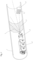
- FIG. 1 shows a section of a pipe 1 in a sectional view.
- the pipe 1 there is a device for inspecting and/or cleaning pipes according to a first embodiment of the invention in the form of an inspection vehicle 2 with a probe 3 arranged on it.
- a camera is arranged on the front side of the probe 3 and looks forward in a longitudinal direction of the pipe 1 . Details of the probe 3 are given with reference to FIG Figures 3 to 6 explained in more detail in the description of the other exemplary embodiments. The details of the probe 3, camera, sensors and light sources are transferable to the present first embodiment.
- the longitudinal direction of the pipe 1 typically coincides with a main axis of the probe 3 during the pipe inspection.
- the inspection vehicle 2 is equipped here with three axles and six wheels purely by way of example, although this does not restrict the invention.
- the probe 3 can be attached to a mechanical lifting arm of the inspection vehicle 2 or rigidly connected to a chassis of the inspection vehicle 2 .
- the image of the probe 3 camera off figure 1 is in 2 displayed on a monitor 8.
- reference number 4 is in 1 and 2
- a first focusing area is shown on a pipe wall, with the first focusing area 4 corresponding to an outer area of the monitor image in the camera image on the monitor 8 .
- the focusing area 4 lies within a detection area 7 of a TOF sensor.
- the object 6 in the pipe 1 is also in the detection range 7 of the TOF sensor.
- the object 6 defines a second focusing range 5 which corresponds to the distance of the TOF sensor from the object 6 .
- the object 6 can be seen near the center of the image.
- the TOF sensor is part of or forms a measuring device for measuring a pipe geometry and for measuring a distance of the probe 3 from the object 6 located in the pipe 1.
- the measuring device is coupled to a control device which is set up to include a focusing unit and/or a lighting unit of the camera based on the measurement data of the TOF sensor setting.
- the focusing unit is typically coupled directly to the camera and preferably includes at least one mechanically and/or magnetically adjustable lens or a liquid lens for setting the focus.
- the image of the monitor 8 can be focused both on the first focusing area 4 and on the second focusing area 5 . This can be done either through user action or automatically.
- the device preferably always focuses on the object 6 located in the tube 1.
- the device only focuses on the first focus area 4 on the tube wall if no object 6 is detected.
- the areas that can be focused are displayed to the user, for example by optically highlighting or marking the area, so that the user selects the desired area to be focused manually, in particular for example by operating a touchscreen, using a mouse, keyboard or the like.
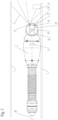
- FIG. 3 shows a device for inspecting and/or cleaning pipes according to a second embodiment of the invention in the form of a probe 3 which is pushed through a pipe 1 on a sliding eel 22 .
- the pusher eel 22 is typically a flexible cable that has sufficient strength and bending stiffness to push the probe 3 through the pipe 1.
- the sliding eel 22 usually also contains the electronics for transmitting the video signal from a camera 13.
- the probe 3 includes the camera 13 and a control device 12 which is connected to the camera 13 .
- the video signal from the camera 13 can be forwarded to the user via the control device 12 .
- the control device 12 is coupled to a focusing unit 16 in order to set it using measurement data from the TOF sensor 11 .
- the detection range 7 of the TOF sensor 11 is such that it can detect both a pipe geometry and a distance from the TOF sensor 11 or the probe 3 to an object 6 located in the pipe 1 .
- the camera 13 is rotatably mounted on the probe 3 about a first axis of rotation 10 perpendicular to a main axis of the probe 3 .
- the camera 13 is itself arranged on the first axis of rotation 10, so that within the scope of the present disclosure a rotation and not a pivoting is spoken of.
- the camera 13 can be angled up or down by rotating it about the first axis of rotation 10, so that, for example, both the upper pipe wall section and the lower pipe wall section are displayed at the same distance from the camera 13 on the image on the monitor 8. In this way, in particular, a uniform illumination of the camera image can be achieved, as will be described in more detail below.
- the camera 13 is rotatably mounted on the probe about a second axis of rotation 9 . Since the camera 13 is arranged on the second axis of rotation 9, this is again referred to as rotation and not panning.
- the camera 13 By rotating the camera 13 about the second axis of rotation 9, for example in conjunction with a gravity sensor (not shown) arranged in the probe 3, it can be ensured that the camera 13 can always output an image regardless of the actual position of the probe 3 in the pipe 1, which allows the user to assign the directions up, down, left and right.
- the position of the first axis of rotation 10 can also be defined by rotating the probe 3 about the second axis of rotation 9 .
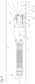
- the rotary encoder can be installed in probe 3. while in 3 a horizontal position of the first axis of rotation 10 is shown, shows 4 a vertical position of the first axis of rotation 10. By rotating about the first axis of rotation 10 in the 4 The vertical position shown, the camera 13 can be turned to the side in the pipe 1, for example for the inspection of branches, as with reference to FIG figure 5 is described in more detail.
- the probe 3 also includes an illumination device 14 in the front area.
- the illumination device 14 is equipped with optional optics 15 .
- the optics 15 can be used by the control device 12 to influence the outgoing light cone, in particular to focus or widen it.
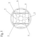
- figure 5 shows a front view of the head of the probe 3.
- the focusing unit 16 of the camera 13 is shown.
- Four light sources 17 are arranged around the camera 13 here, by way of example but without limitation, which can be controlled by the control device 12 preferably individually or in groups with regard to their brightness, particularly preferably also with regard to the alignment of their light cones.
- the light sources 17 can, for example be LED lamps or laser devices.
- the control device 12 can, for example, set the brightness of the individual light sources 17 individually or in groups using the measurement data from the TOF sensor 11, for example by dimming or brightening. As an alternative or in addition to this, the control device 12 can switch the light sources 17 on and off individually or in groups using the measurement data from the TOF sensor 11 .
- the light sources 17 are arranged in a ring around the camera 13 on the probe 3, purely by way of example but not by way of limitation.
- the TOF sensor 11 is located next to the camera 13 and, as in 3 visible, slightly inclined relative to the camera 13, so that the detection areas overlap as extensively as possible.
- the inclination of the TOF sensor 11 is neither mandatory for the invention nor true to scale 3 shown.
- a high-pressure hose 23 serves as a line for a high-pressure agent and includes a nozzle head with a plurality of nozzles 18, by means of which the probe 3 through the pipe 1 can be advanced through the pipe 1, with a pressure medium such as water or compressed air emerging from the nozzles in order to advance the probe 3 through the pipe 1.
- the probe 3 is attached to a connection 26 in a detachable and replaceable manner on the high-pressure hose 23 with the nozzle head.
- a metal spring 25, for example, is provided between the connection 26 and the nozzle head.
- a video signal cable 24 is also connected to the probe 3 via the connector 26 in order to transmit the video signal from the camera 13 .
- the probe 3 includes, in particular, the camera 13 , which is mounted so that it can rotate twice, and the TOF sensor 11 .
- the detection range 7 of the TOF sensor 11 essentially coincides with the detection range 20 of the camera 13 .
- the probe 3 can be provided with a Bowden cable in order to provide a turning function into the pipe branch 21 .
- the probe 3 can be equipped with additional nozzles (not shown), which can be activated by the user, so that the pressure medium emerges in order to navigate the probe 3 into the pipe branch 21, i.e. enabling a turning function.
- additional nozzles not shown
- the depth of focus can be set in such a way that the area of the pipe branch 21 is completely or essentially completely in focus.
Landscapes
- Engineering & Computer Science (AREA)
- Mechanical Engineering (AREA)
- General Physics & Mathematics (AREA)
- Physics & Mathematics (AREA)
- Hydrology & Water Resources (AREA)
- Water Supply & Treatment (AREA)
- General Engineering & Computer Science (AREA)
- Public Health (AREA)
- Health & Medical Sciences (AREA)
- Life Sciences & Earth Sciences (AREA)
- Chemical & Material Sciences (AREA)
- Combustion & Propulsion (AREA)
- Investigating Materials By The Use Of Optical Means Adapted For Particular Applications (AREA)
Priority Applications (1)
| Application Number | Priority Date | Filing Date | Title |
|---|---|---|---|
| EP21218234.9A EP4206814B1 (fr) | 2021-12-29 | 2021-12-29 | Dispositif d'inspection des tuyaux et de canalisation |
Applications Claiming Priority (1)
| Application Number | Priority Date | Filing Date | Title |
|---|---|---|---|
| EP21218234.9A EP4206814B1 (fr) | 2021-12-29 | 2021-12-29 | Dispositif d'inspection des tuyaux et de canalisation |
Publications (3)
| Publication Number | Publication Date |
|---|---|
| EP4206814A1 true EP4206814A1 (fr) | 2023-07-05 |
| EP4206814B1 EP4206814B1 (fr) | 2025-08-20 |
| EP4206814C0 EP4206814C0 (fr) | 2025-08-20 |
Family
ID=79185907
Family Applications (1)
| Application Number | Title | Priority Date | Filing Date |
|---|---|---|---|
| EP21218234.9A Active EP4206814B1 (fr) | 2021-12-29 | 2021-12-29 | Dispositif d'inspection des tuyaux et de canalisation |
Country Status (1)
| Country | Link |
|---|---|
| EP (1) | EP4206814B1 (fr) |
Cited By (2)
| Publication number | Priority date | Publication date | Assignee | Title |
|---|---|---|---|---|
| CN118168465A (zh) * | 2024-05-14 | 2024-06-11 | 莱州龙生汽车零部件有限公司 | 风扇驱动支架内孔测量仪器 |
| CN119959359A (zh) * | 2025-04-08 | 2025-05-09 | 东北大学 | 一种用于大型三维地质模型的全自动超声扫描成像装置 |
Citations (7)
| Publication number | Priority date | Publication date | Assignee | Title |
|---|---|---|---|---|
| US6249007B1 (en) * | 1997-09-12 | 2001-06-19 | Thames Water Utilities Limited | Non-contact distance measuring apparatus |
| US20040177681A1 (en) * | 2002-04-05 | 2004-09-16 | Harthorn Larry K. | Internal riser inspection device and methods of using same |
| EP2975455A1 (fr) | 2014-07-17 | 2016-01-20 | Ipek International GmbH | Systeme de focalisation et unite de camera dotee d'un systeme de focalisation |
| KR101664365B1 (ko) * | 2015-08-10 | 2016-10-19 | (주)씨소 | 파이프에 대한 3차원 스캔 영상 생성 방법 |
| GB2573757A (en) * | 2018-05-14 | 2019-11-20 | Mini Cam Ltd | A pipe inspection apparatus, system and method |
| DE102009057284B4 (de) | 2009-12-07 | 2020-07-30 | Ritec Rohrinspektionstechnik Gmbh | Vorrichtung zur Inspektion und/oder Reinigung von Leitungen für industrielles, häusliches und gewerbliches Abwasser, insbesondere von Kanalrohren für Abwässer |
| GB2593497A (en) * | 2020-03-25 | 2021-09-29 | Q Bot Ltd | A spray unit for a remotely operable spray apparatus and apparatus for spraying thermally insulative material |
-
2021
- 2021-12-29 EP EP21218234.9A patent/EP4206814B1/fr active Active
Patent Citations (7)
| Publication number | Priority date | Publication date | Assignee | Title |
|---|---|---|---|---|
| US6249007B1 (en) * | 1997-09-12 | 2001-06-19 | Thames Water Utilities Limited | Non-contact distance measuring apparatus |
| US20040177681A1 (en) * | 2002-04-05 | 2004-09-16 | Harthorn Larry K. | Internal riser inspection device and methods of using same |
| DE102009057284B4 (de) | 2009-12-07 | 2020-07-30 | Ritec Rohrinspektionstechnik Gmbh | Vorrichtung zur Inspektion und/oder Reinigung von Leitungen für industrielles, häusliches und gewerbliches Abwasser, insbesondere von Kanalrohren für Abwässer |
| EP2975455A1 (fr) | 2014-07-17 | 2016-01-20 | Ipek International GmbH | Systeme de focalisation et unite de camera dotee d'un systeme de focalisation |
| KR101664365B1 (ko) * | 2015-08-10 | 2016-10-19 | (주)씨소 | 파이프에 대한 3차원 스캔 영상 생성 방법 |
| GB2573757A (en) * | 2018-05-14 | 2019-11-20 | Mini Cam Ltd | A pipe inspection apparatus, system and method |
| GB2593497A (en) * | 2020-03-25 | 2021-09-29 | Q Bot Ltd | A spray unit for a remotely operable spray apparatus and apparatus for spraying thermally insulative material |
Cited By (2)
| Publication number | Priority date | Publication date | Assignee | Title |
|---|---|---|---|---|
| CN118168465A (zh) * | 2024-05-14 | 2024-06-11 | 莱州龙生汽车零部件有限公司 | 风扇驱动支架内孔测量仪器 |
| CN119959359A (zh) * | 2025-04-08 | 2025-05-09 | 东北大学 | 一种用于大型三维地质模型的全自动超声扫描成像装置 |
Also Published As
| Publication number | Publication date |
|---|---|
| EP4206814B1 (fr) | 2025-08-20 |
| EP4206814C0 (fr) | 2025-08-20 |
Similar Documents
| Publication | Publication Date | Title |
|---|---|---|
| EP2975455B1 (fr) | Systeme de focalisation et unite de camera dotee d'un systeme de focalisation | |
| DE202021003909U1 (de) | Rohr- und Kanalinspektionsvorrichtung | |
| DE102007017747B4 (de) | Verfahren und Vorrichtung zur optischen Vermessung von Außengewinden | |
| EP1761759B1 (fr) | Procede pour commander une installation de controle de tubes et pour evaluer les donnees de controle | |
| EP2511648B1 (fr) | Agencement de mesure et procédé de détermination d'au moins une hauteur de sertissage d'un sertissage de conducteur | |
| EP4206814B1 (fr) | Dispositif d'inspection des tuyaux et de canalisation | |
| EP3599510B1 (fr) | Système d'inspection de cavités | |
| EP3346230B1 (fr) | Dispositif et procede de mesure de la courbure d'un fil | |
| DE102013019951B4 (de) | Lichtmikroskop und Mikroskopieverfahren zum Untersuchen mehrerer mikroskopischer Objekte | |
| EP3950159A1 (fr) | Système de nettoyage, programme informatique et signal de support de données | |
| DE102004052508B4 (de) | System und Verfahren zum Vermessen und zum Überwachen der Oberfläche eines Körpers | |
| DE202013100437U1 (de) | Vorrichtung zur Abstandsmessung in Rohrleitungen | |
| EP2215396A1 (fr) | Dispositif de durcissement de films plastiques employés pour la réfection de canalisations | |
| DE102017108053A1 (de) | Vorrichtung für Inspektions- und/oder Wartungsarbeiten in begehbaren oder unbegehbaren Kanalisationsanlagen mit einer digitalen Kamera | |
| DE19803679A1 (de) | Vorrichtung zur optischen Abtastung eines Objekts | |
| DE102012204498B4 (de) | Kanalrohrinspektionsvorrichtung und Verfahren zum Inspizieren von Kanalrohren | |
| DE102012215624B3 (de) | Optische Anordnung | |
| DE102019101415A1 (de) | Fahrunterstützungsverfahren | |
| AT408385B (de) | Verfahren und vorrichtung zur erfassung eines abbildes einer im wesentlichen zylindrischen oberfläche | |
| DE202011100462U1 (de) | Kanalrohrroboter | |
| DE29604865U1 (de) | Vorrichtung zur Innenuntersuchung von Rohren, mit einer Sonde | |
| EP3352011B1 (fr) | Système d'inspection pour corps creux | |
| EP3515283A1 (fr) | Système endoscopique et source lumineuse d'un système endoscopique | |
| DE202012012576U1 (de) | Messvorrichtung für eine Kanalinspektionsvorrichtung | |
| DE202016000435U1 (de) | Inspektionsvorrichtung für Rohre |
Legal Events
| Date | Code | Title | Description |
|---|---|---|---|
| PUAI | Public reference made under article 153(3) epc to a published international application that has entered the european phase |
Free format text: ORIGINAL CODE: 0009012 |
|
| STAA | Information on the status of an ep patent application or granted ep patent |
Free format text: STATUS: REQUEST FOR EXAMINATION WAS MADE |
|
| 17P | Request for examination filed |
Effective date: 20211229 |
|
| AK | Designated contracting states |
Kind code of ref document: A1 Designated state(s): AL AT BE BG CH CY CZ DE DK EE ES FI FR GB GR HR HU IE IS IT LI LT LU LV MC MK MT NL NO PL PT RO RS SE SI SK SM TR |
|
| GRAP | Despatch of communication of intention to grant a patent |
Free format text: ORIGINAL CODE: EPIDOSNIGR1 |
|
| STAA | Information on the status of an ep patent application or granted ep patent |
Free format text: STATUS: GRANT OF PATENT IS INTENDED |
|
| INTG | Intention to grant announced |
Effective date: 20250313 |
|
| GRAS | Grant fee paid |
Free format text: ORIGINAL CODE: EPIDOSNIGR3 |
|
| GRAA | (expected) grant |
Free format text: ORIGINAL CODE: 0009210 |
|
| STAA | Information on the status of an ep patent application or granted ep patent |
Free format text: STATUS: THE PATENT HAS BEEN GRANTED |
|
| AK | Designated contracting states |
Kind code of ref document: B1 Designated state(s): AL AT BE BG CH CY CZ DE DK EE ES FI FR GB GR HR HU IE IS IT LI LT LU LV MC MK MT NL NO PL PT RO RS SE SI SK SM TR |
|
| REG | Reference to a national code |
Ref country code: GB Ref legal event code: FG4D Free format text: NOT ENGLISH |
|
| REG | Reference to a national code |
Ref country code: CH Ref legal event code: EP |
|
| REG | Reference to a national code |
Ref country code: IE Ref legal event code: FG4D Free format text: LANGUAGE OF EP DOCUMENT: GERMAN |
|
| REG | Reference to a national code |
Ref country code: DE Ref legal event code: R096 Ref document number: 502021008396 Country of ref document: DE |
|
| U01 | Request for unitary effect filed |
Effective date: 20250828 |
|
| U07 | Unitary effect registered |
Designated state(s): AT BE BG DE DK EE FI FR IT LT LU LV MT NL PT RO SE SI Effective date: 20250904 |
|
| PG25 | Lapsed in a contracting state [announced via postgrant information from national office to epo] |
Ref country code: IS Free format text: LAPSE BECAUSE OF FAILURE TO SUBMIT A TRANSLATION OF THE DESCRIPTION OR TO PAY THE FEE WITHIN THE PRESCRIBED TIME-LIMIT Effective date: 20251220 |
|
| PG25 | Lapsed in a contracting state [announced via postgrant information from national office to epo] |
Ref country code: NO Free format text: LAPSE BECAUSE OF FAILURE TO SUBMIT A TRANSLATION OF THE DESCRIPTION OR TO PAY THE FEE WITHIN THE PRESCRIBED TIME-LIMIT Effective date: 20251120 |
|
| PG25 | Lapsed in a contracting state [announced via postgrant information from national office to epo] |
Ref country code: HR Free format text: LAPSE BECAUSE OF FAILURE TO SUBMIT A TRANSLATION OF THE DESCRIPTION OR TO PAY THE FEE WITHIN THE PRESCRIBED TIME-LIMIT Effective date: 20250820 |
|
| PG25 | Lapsed in a contracting state [announced via postgrant information from national office to epo] |
Ref country code: GR Free format text: LAPSE BECAUSE OF FAILURE TO SUBMIT A TRANSLATION OF THE DESCRIPTION OR TO PAY THE FEE WITHIN THE PRESCRIBED TIME-LIMIT Effective date: 20251121 |
|
| PG25 | Lapsed in a contracting state [announced via postgrant information from national office to epo] |
Ref country code: PL Free format text: LAPSE BECAUSE OF FAILURE TO SUBMIT A TRANSLATION OF THE DESCRIPTION OR TO PAY THE FEE WITHIN THE PRESCRIBED TIME-LIMIT Effective date: 20250820 |
|
| PG25 | Lapsed in a contracting state [announced via postgrant information from national office to epo] |
Ref country code: RS Free format text: LAPSE BECAUSE OF FAILURE TO SUBMIT A TRANSLATION OF THE DESCRIPTION OR TO PAY THE FEE WITHIN THE PRESCRIBED TIME-LIMIT Effective date: 20251120 |
|
| PG25 | Lapsed in a contracting state [announced via postgrant information from national office to epo] |
Ref country code: ES Free format text: LAPSE BECAUSE OF FAILURE TO SUBMIT A TRANSLATION OF THE DESCRIPTION OR TO PAY THE FEE WITHIN THE PRESCRIBED TIME-LIMIT Effective date: 20250820 |
|
| U20 | Renewal fee for the european patent with unitary effect paid |
Year of fee payment: 5 Effective date: 20251230 |
|
| PG25 | Lapsed in a contracting state [announced via postgrant information from national office to epo] |
Ref country code: SM Free format text: LAPSE BECAUSE OF FAILURE TO SUBMIT A TRANSLATION OF THE DESCRIPTION OR TO PAY THE FEE WITHIN THE PRESCRIBED TIME-LIMIT Effective date: 20250820 |
|
| PG25 | Lapsed in a contracting state [announced via postgrant information from national office to epo] |
Ref country code: CZ Free format text: LAPSE BECAUSE OF FAILURE TO SUBMIT A TRANSLATION OF THE DESCRIPTION OR TO PAY THE FEE WITHIN THE PRESCRIBED TIME-LIMIT Effective date: 20250820 |
|
| PG25 | Lapsed in a contracting state [announced via postgrant information from national office to epo] |
Ref country code: SK Free format text: LAPSE BECAUSE OF FAILURE TO SUBMIT A TRANSLATION OF THE DESCRIPTION OR TO PAY THE FEE WITHIN THE PRESCRIBED TIME-LIMIT Effective date: 20250820 |