EP4207548A1 - Batterieverwaltungsvorrichtung und betriebsverfahren dafür - Google Patents
Batterieverwaltungsvorrichtung und betriebsverfahren dafür Download PDFInfo
- Publication number
- EP4207548A1 EP4207548A1 EP22825123.7A EP22825123A EP4207548A1 EP 4207548 A1 EP4207548 A1 EP 4207548A1 EP 22825123 A EP22825123 A EP 22825123A EP 4207548 A1 EP4207548 A1 EP 4207548A1
- Authority
- EP
- European Patent Office
- Prior art keywords
- battery packs
- battery
- precharge
- voltage
- result value
- Prior art date
- Legal status (The legal status is an assumption and is not a legal conclusion. Google has not performed a legal analysis and makes no representation as to the accuracy of the status listed.)
- Granted
Links
Images





Classifications
-
- G—PHYSICS
- G01—MEASURING; TESTING
- G01R—MEASURING ELECTRIC VARIABLES; MEASURING MAGNETIC VARIABLES
- G01R31/00—Arrangements for testing electric properties; Arrangements for locating electric faults; Arrangements for electrical testing characterised by what is being tested not provided for elsewhere
- G01R31/36—Arrangements for testing, measuring or monitoring the electrical condition of accumulators or electric batteries, e.g. capacity or state of charge [SoC]
- G01R31/396—Acquisition or processing of data for testing or for monitoring individual cells or groups of cells within a battery
-
- H—ELECTRICITY
- H01—ELECTRIC ELEMENTS
- H01M—PROCESSES OR MEANS, e.g. BATTERIES, FOR THE DIRECT CONVERSION OF CHEMICAL ENERGY INTO ELECTRICAL ENERGY
- H01M10/00—Secondary cells; Manufacture thereof
- H01M10/42—Methods or arrangements for servicing or maintenance of secondary cells or secondary half-cells
-
- H—ELECTRICITY
- H02—GENERATION; CONVERSION OR DISTRIBUTION OF ELECTRIC POWER
- H02J—ELECTRIC POWER NETWORKS; CIRCUIT ARRANGEMENTS OR SYSTEMS FOR SUPPLYING OR DISTRIBUTING ELECTRIC POWER; SYSTEMS FOR STORING ELECTRIC ENERGY
- H02J7/00—Circuit arrangements for charging or discharging batteries or for supplying loads from batteries
- H02J7/60—Circuit arrangements for charging or discharging batteries or for supplying loads from batteries including safety or protection arrangements
- H02J7/663—Circuit arrangements for charging or discharging batteries or for supplying loads from batteries including safety or protection arrangements using battery or load disconnect circuits
-
- G—PHYSICS
- G01—MEASURING; TESTING
- G01R—MEASURING ELECTRIC VARIABLES; MEASURING MAGNETIC VARIABLES
- G01R31/00—Arrangements for testing electric properties; Arrangements for locating electric faults; Arrangements for electrical testing characterised by what is being tested not provided for elsewhere
- G01R31/36—Arrangements for testing, measuring or monitoring the electrical condition of accumulators or electric batteries, e.g. capacity or state of charge [SoC]
- G01R31/382—Arrangements for monitoring battery or accumulator variables, e.g. SoC
- G01R31/3835—Arrangements for monitoring battery or accumulator variables, e.g. SoC involving only voltage measurements
-
- H—ELECTRICITY
- H01—ELECTRIC ELEMENTS
- H01M—PROCESSES OR MEANS, e.g. BATTERIES, FOR THE DIRECT CONVERSION OF CHEMICAL ENERGY INTO ELECTRICAL ENERGY
- H01M10/00—Secondary cells; Manufacture thereof
- H01M10/42—Methods or arrangements for servicing or maintenance of secondary cells or secondary half-cells
- H01M10/4207—Methods or arrangements for servicing or maintenance of secondary cells or secondary half-cells for several batteries or cells simultaneously or sequentially
-
- H—ELECTRICITY
- H01—ELECTRIC ELEMENTS
- H01M—PROCESSES OR MEANS, e.g. BATTERIES, FOR THE DIRECT CONVERSION OF CHEMICAL ENERGY INTO ELECTRICAL ENERGY
- H01M10/00—Secondary cells; Manufacture thereof
- H01M10/42—Methods or arrangements for servicing or maintenance of secondary cells or secondary half-cells
- H01M10/425—Structural combination with electronic components, e.g. electronic circuits integrated to the outside of the casing
-
- H—ELECTRICITY
- H01—ELECTRIC ELEMENTS
- H01M—PROCESSES OR MEANS, e.g. BATTERIES, FOR THE DIRECT CONVERSION OF CHEMICAL ENERGY INTO ELECTRICAL ENERGY
- H01M10/00—Secondary cells; Manufacture thereof
- H01M10/42—Methods or arrangements for servicing or maintenance of secondary cells or secondary half-cells
- H01M10/44—Methods for charging or discharging
-
- H—ELECTRICITY
- H01—ELECTRIC ELEMENTS
- H01M—PROCESSES OR MEANS, e.g. BATTERIES, FOR THE DIRECT CONVERSION OF CHEMICAL ENERGY INTO ELECTRICAL ENERGY
- H01M10/00—Secondary cells; Manufacture thereof
- H01M10/42—Methods or arrangements for servicing or maintenance of secondary cells or secondary half-cells
- H01M10/48—Accumulators combined with arrangements for measuring, testing or indicating the condition of cells, e.g. the level or density of the electrolyte
-
- H—ELECTRICITY
- H02—GENERATION; CONVERSION OR DISTRIBUTION OF ELECTRIC POWER
- H02J—ELECTRIC POWER NETWORKS; CIRCUIT ARRANGEMENTS OR SYSTEMS FOR SUPPLYING OR DISTRIBUTING ELECTRIC POWER; SYSTEMS FOR STORING ELECTRIC ENERGY
- H02J7/00—Circuit arrangements for charging or discharging batteries or for supplying loads from batteries
- H02J7/50—Circuit arrangements for charging or discharging batteries or for supplying loads from batteries acting upon multiple batteries simultaneously or sequentially
-
- H—ELECTRICITY
- H02—GENERATION; CONVERSION OR DISTRIBUTION OF ELECTRIC POWER
- H02J—ELECTRIC POWER NETWORKS; CIRCUIT ARRANGEMENTS OR SYSTEMS FOR SUPPLYING OR DISTRIBUTING ELECTRIC POWER; SYSTEMS FOR STORING ELECTRIC ENERGY
- H02J7/00—Circuit arrangements for charging or discharging batteries or for supplying loads from batteries
- H02J7/50—Circuit arrangements for charging or discharging batteries or for supplying loads from batteries acting upon multiple batteries simultaneously or sequentially
- H02J7/52—Circuit arrangements for charging or discharging batteries or for supplying loads from batteries acting upon multiple batteries simultaneously or sequentially for charge balancing, e.g. equalisation of charge between batteries
-
- H—ELECTRICITY
- H02—GENERATION; CONVERSION OR DISTRIBUTION OF ELECTRIC POWER
- H02J—ELECTRIC POWER NETWORKS; CIRCUIT ARRANGEMENTS OR SYSTEMS FOR SUPPLYING OR DISTRIBUTING ELECTRIC POWER; SYSTEMS FOR STORING ELECTRIC ENERGY
- H02J7/00—Circuit arrangements for charging or discharging batteries or for supplying loads from batteries
- H02J7/50—Circuit arrangements for charging or discharging batteries or for supplying loads from batteries acting upon multiple batteries simultaneously or sequentially
- H02J7/52—Circuit arrangements for charging or discharging batteries or for supplying loads from batteries acting upon multiple batteries simultaneously or sequentially for charge balancing, e.g. equalisation of charge between batteries
- H02J7/54—Passive balancing, e.g. using resistors or parallel MOSFETs
-
- H—ELECTRICITY
- H02—GENERATION; CONVERSION OR DISTRIBUTION OF ELECTRIC POWER
- H02J—ELECTRIC POWER NETWORKS; CIRCUIT ARRANGEMENTS OR SYSTEMS FOR SUPPLYING OR DISTRIBUTING ELECTRIC POWER; SYSTEMS FOR STORING ELECTRIC ENERGY
- H02J7/00—Circuit arrangements for charging or discharging batteries or for supplying loads from batteries
- H02J7/90—Regulation of charging or discharging current or voltage
- H02J7/96—Regulation of charging or discharging current or voltage in response to battery voltage
-
- H—ELECTRICITY
- H03—ELECTRONIC CIRCUITRY
- H03K—PULSE TECHNIQUE
- H03K17/00—Electronic switching or gating, i.e. not by contact-making and –breaking
- H03K17/51—Electronic switching or gating, i.e. not by contact-making and –breaking characterised by the components used
- H03K17/56—Electronic switching or gating, i.e. not by contact-making and –breaking characterised by the components used by the use, as active elements, of semiconductor devices
- H03K17/687—Electronic switching or gating, i.e. not by contact-making and –breaking characterised by the components used by the use, as active elements, of semiconductor devices the devices being field-effect transistors
- H03K17/6871—Electronic switching or gating, i.e. not by contact-making and –breaking characterised by the components used by the use, as active elements, of semiconductor devices the devices being field-effect transistors the output circuit comprising more than one controlled field-effect transistor
-
- H—ELECTRICITY
- H01—ELECTRIC ELEMENTS
- H01M—PROCESSES OR MEANS, e.g. BATTERIES, FOR THE DIRECT CONVERSION OF CHEMICAL ENERGY INTO ELECTRICAL ENERGY
- H01M10/00—Secondary cells; Manufacture thereof
- H01M10/42—Methods or arrangements for servicing or maintenance of secondary cells or secondary half-cells
- H01M10/425—Structural combination with electronic components, e.g. electronic circuits integrated to the outside of the casing
- H01M2010/4271—Battery management systems including electronic circuits, e.g. control of current or voltage to keep battery in healthy state, cell balancing
-
- H—ELECTRICITY
- H02—GENERATION; CONVERSION OR DISTRIBUTION OF ELECTRIC POWER
- H02J—ELECTRIC POWER NETWORKS; CIRCUIT ARRANGEMENTS OR SYSTEMS FOR SUPPLYING OR DISTRIBUTING ELECTRIC POWER; SYSTEMS FOR STORING ELECTRIC ENERGY
- H02J7/00—Circuit arrangements for charging or discharging batteries or for supplying loads from batteries
- H02J7/80—Circuit arrangements for charging or discharging batteries or for supplying loads from batteries including monitoring or indicating arrangements
-
- Y—GENERAL TAGGING OF NEW TECHNOLOGICAL DEVELOPMENTS; GENERAL TAGGING OF CROSS-SECTIONAL TECHNOLOGIES SPANNING OVER SEVERAL SECTIONS OF THE IPC; TECHNICAL SUBJECTS COVERED BY FORMER USPC CROSS-REFERENCE ART COLLECTIONS [XRACs] AND DIGESTS
- Y02—TECHNOLOGIES OR APPLICATIONS FOR MITIGATION OR ADAPTATION AGAINST CLIMATE CHANGE
- Y02E—REDUCTION OF GREENHOUSE GAS [GHG] EMISSIONS, RELATED TO ENERGY GENERATION, TRANSMISSION OR DISTRIBUTION
- Y02E60/00—Enabling technologies; Technologies with a potential or indirect contribution to GHG emissions mitigation
- Y02E60/10—Energy storage using batteries
Definitions
- Embodiments disclosed herein relate to a battery management apparatus and an operating method thereof.
- the secondary batteries which are chargeable/dischargeable batteries, may include all of conventional nickel (Ni)/cadmium (Cd) batteries, Ni/metal hydride (MH) batteries, etc., and recent lithium-ion batteries.
- a lithium-ion battery has a much higher energy density than those of the conventional Ni/Cd batteries, Ni/MH batteries, etc.
- the lithium-ion battery may be manufactured to be small and lightweight, such that the lithium-ion battery has been used as a power source of mobile devices, and recently, a use range thereof has been extended to power sources for electric vehicles, attracting attention as next-generation energy storage media.
- a plurality of battery packs may be conventionally connected in parallel, but now, a plurality of battery packs may be connected in series at present through the use of a simultaneous interruption technique and a freewheeling diode.
- a precharge resistor is serially connected to the plurality of battery packs connected in series, such that a resistance value increases and thus a magnitude of flowing current decreases, thus increasing a precharge time.
- Embodiments disclosed herein aim to provide a battery management apparatus capable of reducing a precharge time of a plurality of battery packs connected in series.
- a battery management apparatus includes an information obtaining unit configured to obtain a first voltage measured in an output terminal of each of a plurality of battery packs connected in series and a second voltage that is a battery module voltage value of each of the plurality of battery packs and a controller configured to generate a control signal for controlling operations of a precharge relay and a main relay included in each of the plurality of battery packs, based on the first voltage and the second voltage.
- the controller may be further configured to generate a control signal for short-circuiting the precharge relay included in each of the plurality of battery packs and opening the main relay included in each of the plurality of battery packs when operations of the plurality of battery packs connected in series are initiated.
- the controller may be further configured to calculate a first result value by summing first voltages, compare a minimum value among second voltages with the first result value, and generate a control signal for opening a precharge relay included in a battery pack having a second voltage corresponding to the minimum value and short-circuiting a main relay, when the first result value is greater than the minimum value among the second voltages.
- the controller may be further configured to calculate a second result value by summing second voltages of battery packs including short-circuited main relays among the plurality of battery packs, calculate a third result value by summing the second result value and a minimum value among second voltages of battery packs including short-circuited precharge relays among the plurality of battery packs, and compare the first result value with the third result value, and generate the control signal for opening the precharge relay included in the battery pack having the second voltage corresponding to the minimum value among the second voltages of the battery packs including the short-circuited precharge relays and short-circuiting the main relay when the first result value is greater.
- the controller may be further configured to calculate a fourth result value by summing all of second voltages of the plurality of battery packs and generate a control signal for opening precharge relays of the plurality of battery packs and short-circuiting main relays, when a difference between the fourth result value and the first result value is less than or equal to a reference value.
- the main relay and the precharge relay may include any one of a bipolar junction transistor (BJT) or a metal-oxide-semiconductor field-effect transistor (MOSFET).
- BJT bipolar junction transistor
- MOSFET metal-oxide-semiconductor field-effect transistor
- a precharge resistor may be serially connected to the precharge relay.
- the battery module may be provided in plural.
- An operating method of a battery management apparatus includes obtaining a first voltage measured in an output terminal of each of a plurality of battery packs connected in series, obtaining a second voltage that is a battery module voltage value of each of the plurality of battery packs, and generating a control signal for controlling operations of a precharge relay and a main relay included in each of the plurality of battery packs, based on the first voltage and the second voltage.
- the operating method may further include initiating operations of the plurality of battery packs connected in series and generating a control signal for short-circuiting the precharge relay included in each of the plurality of battery packs and opening the main relay included in each of the plurality of battery packs.
- the generating of the control signal for controlling the operations of the precharge relay and the main relay included in each of the plurality of battery packs, based on the first voltage and the second voltage may include calculating a first result value by summing first voltages, comparing a minimum value among second voltages with the first result value, and generating a control signal for opening a precharge relay included in a battery pack having a second voltage corresponding to the minimum value and short-circuiting a main relay, when the first result value is greater than the minimum value among the second voltages.
- the generating of the control signal for controlling the operations of the precharge relay and the main relay included in each of the plurality of battery packs, based on the first voltage and the second voltage may include calculating a second result value by summing second voltages of battery packs including short-circuited main relays among the plurality of battery packs, calculating a third result value by summing the second result value and a minimum value among second voltages of battery packs including short-circuited precharge relays among the plurality of battery packs, and comparing the first result value with the third result value, and generate the control signal for opening the precharge relay included in the battery pack having the second voltage corresponding to the minimum value among the second voltages of the battery packs including the short-circuited precharge relays and short-circuiting the main relay when the first result value is greater.
- the generating of the control signal for controlling the operations of the precharge relay and the main relay included in each of the plurality of battery packs, based on the first voltage and the second voltage may include calculating a fourth result value by summing all of second voltages of the plurality of battery packs; and generating a control signal for opening precharge relays of the plurality of battery packs and short-circuiting main relays, when a difference between the fourth result value and the first result value is less than or equal to a reference value.
- a battery management apparatus may reduce a precharge time by generating a control signal for controlling a main relay and a precharge relay of each of a plurality of battery packs connected in series.
- terms such as first, second, A, B, (a), (b), etc. may be used. These terms are used merely for distinguishing one component from another component and do not limit the component to the essence, sequence, order, etc., of the component.
- the terms used herein, including technical and scientific terms, have the same meanings as terms that are generally understood by those skilled in the art, as long as the terms are not differently defined.
- the terms defined in a generally used dictionary should be interpreted as having the same meanings as the contextual meanings of the relevant technology and should not be interpreted as having ideal or exaggerated meanings unless they are clearly defined in the present application.
- FIG. 1 is a block diagram of a plurality of battery packs and a battery management apparatus, according to an embodiment disclosed herein.
- a battery management apparatus 10 may control a plurality of battery packs 1000.
- the battery management apparatus 10 may control charging and/or discharging of the plurality of battery packs 1000.
- the battery management apparatus 10 may generate a control signal for controlling a main relay (not shown) and a precharge relay (not shown) included in the plurality of battery packs 1000.
- the battery management apparatus 10 may be included in at least any one of battery packs 100, 200, and 300.
- the first battery pack 100 may include the battery management apparatus 10 that may obtain information about the plurality of battery packs 1000 and generate a control signal for controlling the plurality of battery packs 1000.
- the battery management apparatus 10 may perform communication (e.g., Controller Area Network communication) with a battery management apparatus (not shown) included in another battery pack.
- the battery management apparatus 10 may identify a state of each of the plurality of battery packs 1000. For example, the battery management apparatus 10 may identify a battery module voltage value and a voltage value of an output terminal of each of the plurality of battery packs 1000. The battery management apparatus 10 may directly measure a state of each of the plurality of battery packs 1000 and obtain information about a state of each of the plurality of battery packs 1000 from another battery management apparatus (not shown) included in each of the plurality of battery packs 1000.
- the plurality of battery packs 1000 may include the plurality of battery packs 100, 200, and 300.
- the battery packs 100, 200, and 300 may be connected in series.
- each of the battery packs 100, 200, and 300 may include a freewheeling diode.
- the plurality of battery packs 1000 include the three battery packs 100, 200, and 300
- the present invention is not limited thereto. That is, the plurality of battery packs 1000 may include n battery packs (n is a natural number greater than or equal to 2), and the battery management apparatus 10 may identify states of the n battery packs and generate control signals for controlling the n battery packs.
- the battery management apparatus 10 may monitor states of the plurality of battery packs 1000 and generate control signals for controlling the plurality of battery packs 1000 to efficiently perform charging and discharging.
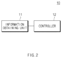
- FIG. 2 is a block diagram of a battery management apparatus according to an embodiment disclosed herein.
- the battery management apparatus 10 may include an information obtaining unit 11 and a controller 12.
- the battery management apparatus 10 may be substantially the same as the battery management apparatus 10 of FIG. 1 . That is, the battery management apparatus 10 may identify the states of the plurality of battery packs 1000 of FIG. 1 and generate control signals for controlling the plurality of battery packs 1000.
- the battery management apparatus 10 will be described.
- the information obtaining unit 11 may obtain a first voltage measured in an output terminal of each of a plurality of battery packs connected in series. For example, the information obtaining unit 11 may obtain a voltage value measured in an output terminal of each of the plurality of battery packs 1000 from an individual battery management apparatus (not shown) included in each of the plurality of battery packs 1000. In another example, the battery management apparatus 10 may directly measure a voltage value of an output terminal of each of the plurality of battery packs 1000, and the information obtaining unit 11 may obtain the measured voltage value.
- the information obtaining unit 11 may obtain a first voltage measured in an output terminal of each of a plurality of battery packs connected in series. For example, the information obtaining unit 11 may obtain a voltage value measured in an output terminal of each of the plurality of battery packs 1000 from an individual battery management apparatus (not shown) included in each of the plurality of battery packs 1000. In another example, the battery management apparatus 10 may directly measure a voltage value of an output terminal of each of the plurality of battery packs 1000, and the information obtaining unit 11 may obtain the measured voltage value.
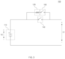
- FIG. 3 illustrates a battery pack according to an embodiment disclosed herein.
- the battery pack 100 (e.g., the first battery pack 100 of FIG. 1 ) according to an embodiment disclosed herein may include a battery module 110, a precharge resistor 120, a precharge relay 130, and a main relay 140.
- the battery pack 100 may be included in the plurality of battery packs 1000 of FIG. 1 . That is, the battery packs 100, 200, and 300 of FIG. 1 may be substantially the same as the battery pack 100 of FIG. 3 .
- the battery management apparatus 10 may obtain a voltage value V1 measured in an output terminal of the battery pack 100.
- the battery management apparatus 10 may directly measure the voltage value of the output terminal of the battery pack 100, and another battery management apparatus (not shown) may be included in the battery pack 100 such that the battery management apparatus 10 may obtain a voltage value of the output terminal of the battery pack 100, measured by the other battery management apparatus (not shown) included in the battery pack 100.
- the battery management apparatus 10 may obtain a voltage value V2 of the battery module 110 of the battery pack 100.
- the battery management apparatus 10 may directly measure the voltage value V2 of the battery module 110, and another battery management apparatus (not shown) may be included in the battery pack 100 such that the battery management apparatus 10 may obtain the voltage value V2 of the battery module 110, measured by the other battery management apparatus (not shown) included in the battery pack 100.
- the battery pack 100 may include the plurality of battery modules 110.
- the battery pack 100 may include the plurality of battery modules 310, and the battery management apparatus 10 may obtain the voltage value V2 of the plurality of battery modules 310 connected in series.
- the battery pack 100 may include n battery modules 110 (n is a natural number greater than or equal to 1).
- the precharge resistor 120 may be a resistor for limiting a speed of charging or discharging to balance a voltage with an external device (at least any one of an inverter, a converter, or a capacitor) in charging or discharging of the battery pack 100.
- the precharge resistor 120 may reduce current flowing through the battery pack 100 in charging or discharging, by making a load inside the battery pack 100.
- the precharge resistor 120 may be serially connected to the precharge relay 130.
- the precharge relay 130 and the main relay 140 may form charging and discharging paths of the battery pack 100.
- the battery pack 100 may short-circuit the precharge relay 130 and open the main relay 140 in a precharge phase, and open the precharge relay 130 and short-circuit the main relay 140 in a main charge phase.
- the battery pack 100 may open both the precharge relay 130 and the main relay 140 when the battery pack 100 is not used.
- operations of the precharge relay 130 and the main relay 140 may be controlled by a control signal delivered from the battery management apparatus 10 of FIG. 2 .
- the precharge relay 130 and the main relay 140 may include any one of a bipolar junction transistor (BJT) or a metal-oxide-semiconductor field-effect transistor (MOSFET).
- BJT bipolar junction transistor
- MOSFET metal-oxide-semiconductor field-effect transistor
- the controller 12 may generate a control signal for controlling operations of a precharge relay and a main relay included in each of the plurality of battery packs 1000, based on a first voltage measured in an output terminal of each of the plurality of battery packs 1000 and a second voltage that is a battery module voltage value (a second voltage of a battery module of each of the plurality of battery packs 1000), in which the first voltage and the second voltage are obtained from the information obtaining unit 11. For example, when the plurality of battery packs 1000 do not operate, the controller 12 may generate a control signal for opening both the precharge relay and the main relay included in each of the plurality of battery packs 1000.
- the controller 12 may generate a control signal for short-circuiting the precharge relay included in each of the plurality of battery packs 1000 and opening the main relay included in each of the plurality of battery packs. For example, when charging or discharging operations of the plurality of battery packs 1000 are initiated, the controller 12 may generate a control signal for short-circuiting the precharge relay included in each of the plurality of battery packs 1000 and opening the main relay included in each of the plurality of battery packs, and the plurality of battery packs 1000 may perform the precharge phase.
- the controller 12 may calculate a first result value by summing the first voltage of each of the plurality of battery packs 1000. For example, the controller 12 may calculate a voltage value measured in an output terminal of the whole plurality of battery packs 1000 connected in series by summing the first voltage of each of the plurality of battery packs 1000. That is, the first result value may be the voltage value measured in the output terminal of the whole plurality of battery packs 1000 connected in series.
- the controller 12 may compare a minimum value among second values of the plurality of battery packs 1000 with the first result value. For example, the controller 12 may find the minimum value by comparing battery module voltage values of the respective plurality of battery packs 1000, and compare the found minimum value with the first result value.
- the controller 12 may generate a control signal for opening the precharge relay included in a battery pack having the second voltage corresponding to the minimum value and short-circuiting the main relay.
- the controller 12 may generate a control signal for opening the precharge relay included in the battery pack having the second voltage corresponding to the minimum value among the second voltages of the plurality of battery packs 1000 and short-circuiting the main relay and transmit the control signal to the battery pack having the second voltage corresponding to the minimum value, and the battery pack having the second voltage corresponding to the minimum value may perform charging or discharging without passing through a precharge resistor by opening the precharge relay and short-circuiting the main relay. That is, a precharge resistance of the whole plurality of battery packs 1000 may decrease.
- the controller 12 may reduce the precharge resistance value by generating a control signal for opening a precharge relay of one of the plurality of battery packs 1000 and short-circuiting a main relay of the battery pack 1000 in the above-described process.
- the controller 12 may calculate a second result value by summing the second voltages of the battery packs including the short-circuited main relays among the plurality of battery packs 1000.
- the controller 12 may find the minimum value among the second voltages of battery packs 1000 including the short-circuited precharge relays and calculate a third result value by summing the minimum value and the second result value.
- the controller 12 may compare the first result value with the third result value, and when the first result value is greater than the third result value, the controller 12 may generate a control signal for opening the precharge relay included in the battery pack having the second voltage corresponding to the minimum value among the second voltages of the battery packs including the short-circuited precharge relays and short-circuiting the main relay.
- the controller 12 may compare the voltage value of the output terminal of the whole plurality of battery packs 1000 with the third result value, and when the voltage value of the output terminal of the whole plurality of battery packs 1000 is greater than the third result value, the controller 12 may generate a control signal for opening the precharge relay included in the battery pack having the second voltage corresponding to the minimum value among the second voltages of the battery packs including the short-circuited precharge relays and short-circuiting the main relay, thereby reducing the precharge resistance value of the whole plurality of battery packs 1000.
- the controller 12 may generate a control signal for opening a precharge relay of a battery pack corresponding to the minimum value among second voltages of battery packs including short-circuited precharge relays among the plurality of battery packs 1000 and short-circuiting a main relay in the above-described process, thereby sequentially reducing the precharge resistance value of the whole plurality of battery packs 1000.
- the controller 12 may calculate a fourth result value by summing the second voltages of the plurality of battery packs 1000. When a difference between the calculated fourth result value and the first result value is less than or equal to a reference value, the controller 12 may generate a control signal for opening the precharge relays of the plurality of battery packs 1000 and short-circuiting the main relays.
- the controller 12 may calculate the fourth result value by summing the battery module voltage values of the respective plurality of battery packs 1000, calculate the first result value by summing the voltage values of the output terminals of the respective plurality of battery packs 1000, compare the fourth result value with the first result value, and generate a control signal for opening the precharge relays of the whole plurality of battery packs 1000 connected in series and short-circuiting the main relays when a difference between the fourth result value and the first result value is less than or equal to a reference value (a threshold value or a set value), thereby completing the precharge phase and going to the main charge phase.
- a reference value a threshold value or a set value
- the controller 12 may compare a voltage value applied to an external device (at least any one of a capacitor, an inverter, or a converter) connected to the plurality of battery packs 1000 with battery module voltage values of the whole plurality of battery packs 1000 and may generate a control signal for opening the precharge relays of the whole plurality of battery packs 1000 and short-circuiting the main relays because the plurality of battery packs 1000 may not be damaged in spite of short-circuiting of the main relays when a difference between the applied voltage value and the battery module voltage values is less than or equal to the reference value.
- an external device at least any one of a capacitor, an inverter, or a converter
- the battery management apparatus 10 may generate a control signal for controlling operations of a precharge relay and a main relay included in each of the plurality of battery packs 1000, based on a voltage value measured in the output terminal of each of the plurality of battery packs 1000 and a battery module voltage value of each of the plurality of battery packs 1000.
- the battery management apparatus 10 may sequentially reduce the number of battery packs in which precharge relays are short-circuited and main relays are opened, thus sequentially reducing the precharge resistance value of the whole plurality of battery packs 1000 and reducing a precharge time of the plurality of battery packs 1000.
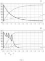
- FIG. 4 shows a precharge time of a plurality of battery packs according to an embodiment disclosed herein.
- first graph 410 that is a graph regarding a precharge time of an existing plurality of battery packs connected in series
- second graph 420 that is a graph regarding a precharge time of a plurality of serially connected battery packs controlled by the battery management apparatus 10
- slopes at which the voltage value V1 and V3 of the output terminal of the whole plurality of battery packs increase are steeper for the battery management apparatus 10 in the second graph 420.
- the voltage V2 of the output terminal of each of the plurality of battery packs is the same until the precharge phase ends because the plurality of battery packs are connected in series
- voltages V3, V4, V5, and V6 of the output terminals of the plurality of battery packs have different values because the battery management apparatus 10 generates a control signal for opening the precharge relay and the main relay when the plurality of battery packs satisfy a predetermined condition, such that a time for completing the precharge phase in the second graph 420 is shorter than a time for completing the precharge phase in the first graph 410.
- an output current I2 in the second graph 420 is higher than an output current I1 in the first graph 410, such that a time in which the precharge phase is completed may be regarded as being shorter in the second graph 420 than in the first graph 410.
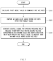
- FIG. 5 is a flowchart of an operating method of a battery management apparatus according to an embodiment disclosed herein.
- an operating method of the battery management apparatus 10 may include operation S 110 of obtaining a first voltage measured in an output terminal of each of a plurality of battery packs connected in series, operation S 120 of obtaining a second voltage that is a battery module voltage value of each of the plurality of battery packs, and operation S 130 of generating a control signal for controlling operations of a precharge relay and a main relay included in each of the plurality of battery packs based on the first voltage and the second voltage.
- the information obtaining unit 11 may obtain a voltage of the output terminal of each of the plurality of serially connected battery packs. For example, the information obtaining unit 11 may obtain the first voltage by directly measuring a voltage value of the output terminal of each of the plurality of battery packs. In another example, the information obtaining unit 11 may obtain the first voltage that is the voltage value of each terminal of each of the plurality of battery packs from each battery management apparatus included in the plurality of battery packs.
- the information obtaining unit 11 may obtain the battery module voltage value of each of the plurality of battery packs.
- the information obtaining unit 11 may obtain the battery module voltage value of each of the plurality of battery packs from each battery management apparatus included in the plurality of battery packs.
- the information obtaining unit 11 may directly measure a battery module voltage value of each of the plurality of battery packs.
- each of the plurality of battery packs may include a plurality of battery modules, and thus a battery module voltage value of each of the plurality of battery packs may be a voltage value of a plurality of serially connected battery modules.
- the controller 12 may generate a control signal for controlling the operations of the precharge relay and the main relay included in each of the plurality of battery packs based on the first voltage and the second voltage obtained in the information obtaining unit 11.
- the precharge relay may be a relay connected to a precharge resistor, and when the precharge relay is short-circuited and the main relay is opened, an internal resistance may increase due to the precharge resistance and in contrast, when the precharge relay is opened and the main relay is short-circuited, the internal resistance may decrease. That is, the controller 12 may adjust a precharge resistance value of the whole plurality of battery packs by generating a control signal for controlling a precharge relay and a main relay included in each of the plurality of battery packs.
- FIG. 6 is a flowchart of operations further included in an operating method of a battery management apparatus according to an embodiment disclosed herein.
- an operating method of the battery management apparatus 10 may further include operation S210 of initiating operations of a plurality of serially connected battery packs and operation S220 of generating a control signal for short-circuiting a precharge relay included in each of the plurality of battery packs and opening a main relay included in each of the plurality of battery packs.
- the controller 12 may identify a state in which the operations of the plurality of serially connected battery packs are initiated. For example, before the operation of each of the plurality of battery packs is initiated, both the precharge relay and the main relay may be in an open state. In another example, the controller 12 may determine whether the plurality of battery packs are in a charged state or a discharged state.
- the controller 12 may generate the control signal for short-circuiting the precharge relay included in each of the plurality of battery packs and opening the main relay included in each of the plurality of battery packs when the operations of the plurality of battery packs are initiated.
- external devices e.g., a capacitor, an inverter, and a converter
- the plurality of battery packs may have a large voltage difference than the battery module voltages of the whole plurality of battery packs and a high current may flow, resulting in a damage.
- the controller 12 may balance a voltage value applied to an external device with a battery module voltage value by first short-circuiting the precharge relay of each of the plurality of battery packs, so as to prevent a damage of the plurality of battery packs or the external device.
- FIGS. 7 and 9 are flowcharts showing in detail operation S130 in an operating method of a battery management apparatus according to an embodiment disclosed herein.
- operation S130 may include operation S310 of calculating a first result value by summing a first voltage, operation S320 of comparing a minimum value among second voltages with the first result value, and operation S330 of generating a control signal for opening a precharge relay included in a battery pack, which has a second voltage corresponding to the minimum value, and short-circuiting a main relay, when the first result value is greater than the minimum value among the second voltages.
- the controller 12 may calculate the first result value by summing the first voltage that is a voltage in an output terminal of each of the plurality of battery packs.
- the first result value may be a voltage value in the output terminal of the whole plurality of battery packs.
- the first result value may be a voltage value applied to an external device connected to the plurality of battery packs.
- the controller 12 may find the minimum value by comparing the second voltages that are battery module voltage values of the respective plurality of battery packs, and compare the minimum value with the first result value.
- the controller 12 may generate a control signal for opening the precharge relay included in the battery pack having the second voltage corresponding to the minimum value and short-circuiting the main relay. For example, the controller 12 may reduce a precharge resistance of all of the plurality of battery packs by generating the control signal for opening the precharge relay included in the battery pack having the second voltage corresponding to the minimum value and short-circuiting the main relay, and reduce a time required for performing the precharge phase by reducing the precharge resistance.
- operation S130 may further include operation S410 of calculating a second result value by summing second voltages of battery packs having short-circuited main relays among the plurality of battery packs, operation S420 of calculating a third result value by summing the second result value and the minimum value among second voltages of battery packs having short-circuited precharge relays, and operation S430 of comparing the first result value with the third result value and generating a control signal for opening a precharge relay included in a battery pack having the second voltage corresponding to the minimum value among the second voltages of the battery packs having the short-circuited precharge relays and short-circuiting a main relay when the first result value is greater.
- the controller 12 may calculate the second result value by summing the second voltages that are battery module voltages of the battery pack having the short-circuited main relays among the plurality of battery packs.
- the controller 12 may find the minimum value by comparing the second voltages of the battery packs having the short-circuited precharge relays among the plurality of battery packs and calculate the third result value by summing the minimum value and the second result value.
- the controller 12 may compare the first result value calculated in operation S310 with the third result value and generate the control signal for opening the precharge relay included in the battery pack having the second voltage corresponding to the minimum value among the second voltages of the battery packs having the short-circuited precharge relays and short-circuiting the main relay when the first result value is greater.
- the controller 12 may periodically compare the first result value with the third result value and generate the control signal for opening a precharge relay of one of battery packs having short-circuited precharge relays and short-circuiting a main relay at a point in time when the first result value is greater, thereby reducing a precharge resistance of the whole plurality of battery packs.
- operation S130 may further include operation S510 of calculating a fourth result value by summing the second voltages of the plurality of battery packs and operation S520 of generating a control signal for opening precharge relays of the plurality of battery packs and short-circuiting main relays when a difference between the fourth result value and the first result value is less than or equal to a reference value.
- the controller 12 may calculate the fourth result value by summing all of the second voltages that are battery module voltage values of the respective plurality of battery packs.
- the fourth result value may be a battery module voltage value of the whole plurality of battery packs.
- the controller 12 may calculate the difference between the fourth result value and the first result value calculated in operation S310, and generate the control signal for opening the precharge packs of the whole plurality of battery packs and short-circuiting the main relays when the difference is less than or equal to the reference value.
- the controller 12 may generate the control signal for opening the precharge relays of the whole plurality of battery packs and short-circuiting the main relays when the difference between the fourth result value and the first result value is less than or equal to the reference value (a threshold value or a set value).
- the operating method of the battery management apparatus 10 disclosed herein may sequentially reduce the number of battery packs having short-circuited precharge relays and opened main relays among the plurality of battery packs by performing the operations of FIGS. 7 to 9 , and generate the control signal for opening the precharge relays of the whole plurality of battery packs and short-circuiting the main relays by performing operation S520 last, thereby terminating the precharge phase. That is, the operating method of the battery management apparatus 10 may reduce a precharge time of the plurality of battery packs connected in series by sequentially increasing the number of battery packs having short-circuited main relays.
Landscapes
- Engineering & Computer Science (AREA)
- Power Engineering (AREA)
- General Chemical & Material Sciences (AREA)
- Chemical & Material Sciences (AREA)
- Chemical Kinetics & Catalysis (AREA)
- Electrochemistry (AREA)
- Manufacturing & Machinery (AREA)
- Physics & Mathematics (AREA)
- General Physics & Mathematics (AREA)
- Microelectronics & Electronic Packaging (AREA)
- Charge And Discharge Circuits For Batteries Or The Like (AREA)
- Secondary Cells (AREA)
- Protection Of Static Devices (AREA)
Applications Claiming Priority (2)
| Application Number | Priority Date | Filing Date | Title |
|---|---|---|---|
| KR1020210078981A KR20220168909A (ko) | 2021-06-17 | 2021-06-17 | 배터리 관리 장치 및 그것의 동작 방법 |
| PCT/KR2022/003880 WO2022265192A1 (ko) | 2021-06-17 | 2022-03-21 | 배터리 관리 장치 및 그것의 동작 방법 |
Publications (3)
| Publication Number | Publication Date |
|---|---|
| EP4207548A1 true EP4207548A1 (de) | 2023-07-05 |
| EP4207548A4 EP4207548A4 (de) | 2024-05-15 |
| EP4207548B1 EP4207548B1 (de) | 2025-11-26 |
Family
ID=84527127
Family Applications (1)
| Application Number | Title | Priority Date | Filing Date |
|---|---|---|---|
| EP22825123.7A Active EP4207548B1 (de) | 2021-06-17 | 2022-03-21 | Batterieverwaltungsvorrichtung und betriebsverfahren dafür |
Country Status (8)
| Country | Link |
|---|---|
| US (1) | US20230333175A1 (de) |
| EP (1) | EP4207548B1 (de) |
| JP (1) | JP7537018B2 (de) |
| KR (1) | KR20220168909A (de) |
| CN (1) | CN116325283A (de) |
| ES (1) | ES3058173T3 (de) |
| PL (1) | PL4207548T3 (de) |
| WO (1) | WO2022265192A1 (de) |
Families Citing this family (1)
| Publication number | Priority date | Publication date | Assignee | Title |
|---|---|---|---|---|
| US12136840B2 (en) * | 2021-12-24 | 2024-11-05 | Motorola Solutions, Inc. | Device, battery and system to control battery power |
Family Cites Families (13)
| Publication number | Priority date | Publication date | Assignee | Title |
|---|---|---|---|---|
| JP4079428B2 (ja) * | 2003-05-26 | 2008-04-23 | Necトーキン株式会社 | 電池パック |
| US7701177B2 (en) * | 2006-12-21 | 2010-04-20 | O2Micro International Limited | Battery pre-charging circuit comprising normal voltage and low voltage pre-charging circuits |
| JP2010057290A (ja) * | 2008-08-28 | 2010-03-11 | Sanyo Electric Co Ltd | 車両用の電源装置 |
| JP5971626B2 (ja) * | 2012-03-15 | 2016-08-17 | 株式会社日立製作所 | 電池システム |
| KR20140131174A (ko) * | 2013-05-03 | 2014-11-12 | 주식회사 엘지화학 | 펄스 폭 변조를 이용하는 프리 차지 기능의 배터리 관리 장치 및 배터리 관리 방법 |
| KR20160099361A (ko) * | 2015-02-12 | 2016-08-22 | 삼성에스디아이 주식회사 | 다병렬 에너지 저장 시스템 및 그 제어 방법 |
| JP2016170938A (ja) * | 2015-03-12 | 2016-09-23 | プライムアースEvエナジー株式会社 | 電池システムの電池パック交換方法及び電池パック |
| US9608458B2 (en) * | 2015-03-18 | 2017-03-28 | NEC Energy Solutons, Inc. | Buck pre-charger for series-connected battery modules |
| CN107482741B (zh) * | 2016-06-13 | 2019-09-20 | 宝沃汽车(中国)有限公司 | 充电控制方法与系统 |
| KR102247391B1 (ko) * | 2016-07-25 | 2021-05-03 | 삼성에스디아이 주식회사 | 배터리 시스템 |
| CN107276170B (zh) * | 2017-07-12 | 2020-06-12 | 合肥国轩高科动力能源有限公司 | 一种主动保护纯电动汽车电池的系统及方法 |
| JP6789910B2 (ja) * | 2017-10-18 | 2020-11-25 | 株式会社東芝 | 電池ユニットおよび電池ユニットの制御方法 |
| CN117044064A (zh) * | 2021-06-17 | 2023-11-10 | 株式会社Lg新能源 | 电池管理装置和方法 |
-
2021
- 2021-06-17 KR KR1020210078981A patent/KR20220168909A/ko not_active Ceased
-
2022
- 2022-03-21 US US18/028,646 patent/US20230333175A1/en active Pending
- 2022-03-21 WO PCT/KR2022/003880 patent/WO2022265192A1/ko not_active Ceased
- 2022-03-21 PL PL22825123.7T patent/PL4207548T3/pl unknown
- 2022-03-21 EP EP22825123.7A patent/EP4207548B1/de active Active
- 2022-03-21 JP JP2023518524A patent/JP7537018B2/ja active Active
- 2022-03-21 ES ES22825123T patent/ES3058173T3/es active Active
- 2022-03-21 CN CN202280006818.7A patent/CN116325283A/zh active Pending
Also Published As
| Publication number | Publication date |
|---|---|
| US20230333175A1 (en) | 2023-10-19 |
| CN116325283A (zh) | 2023-06-23 |
| PL4207548T3 (pl) | 2026-02-23 |
| KR20220168909A (ko) | 2022-12-26 |
| JP7537018B2 (ja) | 2024-08-20 |
| EP4207548B1 (de) | 2025-11-26 |
| JP2023542972A (ja) | 2023-10-12 |
| WO2022265192A1 (ko) | 2022-12-22 |
| EP4207548A4 (de) | 2024-05-15 |
| ES3058173T3 (en) | 2026-03-09 |
Similar Documents
| Publication | Publication Date | Title |
|---|---|---|
| US12074465B2 (en) | Control device, electric storage device, electric storage system, and computer-readable medium | |
| KR101497602B1 (ko) | 배터리 밸런싱 시스템 및 이를 이용한 배터리 밸런싱 방법 | |
| US20250389775A1 (en) | Battery Management Apparatus and Method | |
| CN101714649B (zh) | 电池部件以及使用了该电池部件的电池系统 | |
| US8164305B2 (en) | Battery management system with energy balance among multiple battery cells | |
| EP2418751B1 (de) | Batterieladegerät und Batterieladeverfahren | |
| EP2148384A1 (de) | Batteriesystem, das eine Sekundärbatterie verwendet | |
| US12449485B2 (en) | Battery management apparatus and method | |
| US20060097700A1 (en) | Method and system for cell equalization with charging sources and shunt regulators | |
| JP5314626B2 (ja) | 電源システム、放電制御方法および放電制御プログラム | |
| US20260110739A1 (en) | Battery State Management Apparatus and Operating Method Thereof | |
| US10594143B2 (en) | Charging method for battery set and battery management system using the same | |
| Eskandari et al. | Advanced battery management systems with integrated battery electronics | |
| KR100964316B1 (ko) | 배터리 셀 밸런싱 시스템, 그 방법 및 이를 기록한기록매체 | |
| KR102574696B1 (ko) | 에너지 저장 시스템 및 그 동작 방법 | |
| EP4207548A1 (de) | Batterieverwaltungsvorrichtung und betriebsverfahren dafür | |
| US11398743B2 (en) | Apparatus and method for forming current path according to charging or discharging state of battery pack | |
| US20240243595A1 (en) | Battery Management Apparatus and Operating Method Thereof | |
| EP4236013A1 (de) | Batteriesteuerungssystem und -verfahren | |
| EP4365613B1 (de) | Batteriepack und betriebsverfahren dafür | |
| EP4105668A1 (de) | Relaiszustandsverwaltungsvorrichtung und betriebsverfahren dafür | |
| EP4654328A2 (de) | Batterieverwaltungsvorrichtung | |
| KR20230022012A (ko) | 배터리의 열화 저감방법 및 그 방법을 제공하는 배터리 관리 시스템 | |
| JP2022141451A (ja) | 蓄電池制御装置、蓄電システム、及び蓄電池制御方法 | |
| JP2007250364A (ja) | 二次電池の内部充電装置及び充電方法 |
Legal Events
| Date | Code | Title | Description |
|---|---|---|---|
| STAA | Information on the status of an ep patent application or granted ep patent |
Free format text: STATUS: THE INTERNATIONAL PUBLICATION HAS BEEN MADE |
|
| PUAI | Public reference made under article 153(3) epc to a published international application that has entered the european phase |
Free format text: ORIGINAL CODE: 0009012 |
|
| STAA | Information on the status of an ep patent application or granted ep patent |
Free format text: STATUS: REQUEST FOR EXAMINATION WAS MADE |
|
| 17P | Request for examination filed |
Effective date: 20230330 |
|
| AK | Designated contracting states |
Kind code of ref document: A1 Designated state(s): AL AT BE BG CH CY CZ DE DK EE ES FI FR GB GR HR HU IE IS IT LI LT LU LV MC MK MT NL NO PL PT RO RS SE SI SK SM TR |
|
| A4 | Supplementary search report drawn up and despatched |
Effective date: 20240411 |
|
| RIC1 | Information provided on ipc code assigned before grant |
Ipc: H01M 10/48 20060101ALI20240405BHEP Ipc: H01M 10/44 20060101ALI20240405BHEP Ipc: H03K 17/687 20060101ALI20240405BHEP Ipc: H01M 10/42 20060101ALI20240405BHEP Ipc: H02J 7/00 20060101AFI20240405BHEP |
|
| DAV | Request for validation of the european patent (deleted) | ||
| DAX | Request for extension of the european patent (deleted) | ||
| STAA | Information on the status of an ep patent application or granted ep patent |
Free format text: STATUS: EXAMINATION IS IN PROGRESS |
|
| 17Q | First examination report despatched |
Effective date: 20250115 |
|
| GRAP | Despatch of communication of intention to grant a patent |
Free format text: ORIGINAL CODE: EPIDOSNIGR1 |
|
| STAA | Information on the status of an ep patent application or granted ep patent |
Free format text: STATUS: GRANT OF PATENT IS INTENDED |
|
| INTG | Intention to grant announced |
Effective date: 20250711 |
|
| P01 | Opt-out of the competence of the unified patent court (upc) registered |
Free format text: CASE NUMBER: UPC_APP_4898_4207548/2025 Effective date: 20250827 |
|
| GRAS | Grant fee paid |
Free format text: ORIGINAL CODE: EPIDOSNIGR3 |
|
| GRAA | (expected) grant |
Free format text: ORIGINAL CODE: 0009210 |
|
| STAA | Information on the status of an ep patent application or granted ep patent |
Free format text: STATUS: THE PATENT HAS BEEN GRANTED |
|
| AK | Designated contracting states |
Kind code of ref document: B1 Designated state(s): AL AT BE BG CH CY CZ DE DK EE ES FI FR GB GR HR HU IE IS IT LI LT LU LV MC MK MT NL NO PL PT RO RS SE SI SK SM TR |
|
| REG | Reference to a national code |
Ref country code: CH Ref legal event code: F10 Free format text: ST27 STATUS EVENT CODE: U-0-0-F10-F00 (AS PROVIDED BY THE NATIONAL OFFICE) Effective date: 20251126 Ref country code: GB Ref legal event code: FG4D |
|
| REG | Reference to a national code |
Ref country code: DE Ref legal event code: R096 Ref document number: 602022025794 Country of ref document: DE |
|
| REG | Reference to a national code |
Ref country code: IE Ref legal event code: FG4D |
|
| REG | Reference to a national code |
Ref country code: SE Ref legal event code: TRGR |
|
| REG | Reference to a national code |
Ref country code: ES Ref legal event code: FG2A Ref document number: 3058173 Country of ref document: ES Kind code of ref document: T3 Effective date: 20260309 |
|
| REG | Reference to a national code |
Ref country code: NL Ref legal event code: MP Effective date: 20251126 |
|
| PGFP | Annual fee paid to national office [announced via postgrant information from national office to epo] |
Ref country code: SE Payment date: 20260223 Year of fee payment: 5 |
|
| PGFP | Annual fee paid to national office [announced via postgrant information from national office to epo] |
Ref country code: GB Payment date: 20260224 Year of fee payment: 5 |
|
| REG | Reference to a national code |
Ref country code: LT Ref legal event code: MG9D |
|
| PG25 | Lapsed in a contracting state [announced via postgrant information from national office to epo] |
Ref country code: NO Free format text: LAPSE BECAUSE OF FAILURE TO SUBMIT A TRANSLATION OF THE DESCRIPTION OR TO PAY THE FEE WITHIN THE PRESCRIBED TIME-LIMIT Effective date: 20260226 |
|
| PGFP | Annual fee paid to national office [announced via postgrant information from national office to epo] |
Ref country code: DE Payment date: 20260220 Year of fee payment: 5 |
|
| PG25 | Lapsed in a contracting state [announced via postgrant information from national office to epo] |
Ref country code: FI Free format text: LAPSE BECAUSE OF FAILURE TO SUBMIT A TRANSLATION OF THE DESCRIPTION OR TO PAY THE FEE WITHIN THE PRESCRIBED TIME-LIMIT Effective date: 20251126 Ref country code: HR Free format text: LAPSE BECAUSE OF FAILURE TO SUBMIT A TRANSLATION OF THE DESCRIPTION OR TO PAY THE FEE WITHIN THE PRESCRIBED TIME-LIMIT Effective date: 20251126 Ref country code: AT Free format text: LAPSE BECAUSE OF FAILURE TO SUBMIT A TRANSLATION OF THE DESCRIPTION OR TO PAY THE FEE WITHIN THE PRESCRIBED TIME-LIMIT Effective date: 20251126 |
|
| PGFP | Annual fee paid to national office [announced via postgrant information from national office to epo] |
Ref country code: AT Payment date: 20260301 Year of fee payment: 5 |
|
| PGFP | Annual fee paid to national office [announced via postgrant information from national office to epo] |
Ref country code: BE Payment date: 20260220 Year of fee payment: 5 |
|
| REG | Reference to a national code |
Ref country code: AT Ref legal event code: MK05 Ref document number: 1862109 Country of ref document: AT Kind code of ref document: T Effective date: 20251126 |
|
| PG25 | Lapsed in a contracting state [announced via postgrant information from national office to epo] |
Ref country code: NL Free format text: LAPSE BECAUSE OF FAILURE TO SUBMIT A TRANSLATION OF THE DESCRIPTION OR TO PAY THE FEE WITHIN THE PRESCRIBED TIME-LIMIT Effective date: 20251126 |
|
| PGFP | Annual fee paid to national office [announced via postgrant information from national office to epo] |
Ref country code: HU Payment date: 20260310 Year of fee payment: 5 |
|
| PG25 | Lapsed in a contracting state [announced via postgrant information from national office to epo] |
Ref country code: RS Free format text: LAPSE BECAUSE OF FAILURE TO SUBMIT A TRANSLATION OF THE DESCRIPTION OR TO PAY THE FEE WITHIN THE PRESCRIBED TIME-LIMIT Effective date: 20260226 |
|
| PG25 | Lapsed in a contracting state [announced via postgrant information from national office to epo] |
Ref country code: IS Free format text: LAPSE BECAUSE OF FAILURE TO SUBMIT A TRANSLATION OF THE DESCRIPTION OR TO PAY THE FEE WITHIN THE PRESCRIBED TIME-LIMIT Effective date: 20260326 |
|
| PGFP | Annual fee paid to national office [announced via postgrant information from national office to epo] |
Ref country code: FR Payment date: 20260224 Year of fee payment: 5 |
|
| PG25 | Lapsed in a contracting state [announced via postgrant information from national office to epo] |
Ref country code: PT Free format text: LAPSE BECAUSE OF FAILURE TO SUBMIT A TRANSLATION OF THE DESCRIPTION OR TO PAY THE FEE WITHIN THE PRESCRIBED TIME-LIMIT Effective date: 20260326 |
|
| PGFP | Annual fee paid to national office [announced via postgrant information from national office to epo] |
Ref country code: PL Payment date: 20260223 Year of fee payment: 5 |
|
| PG25 | Lapsed in a contracting state [announced via postgrant information from national office to epo] |
Ref country code: LV Free format text: LAPSE BECAUSE OF FAILURE TO SUBMIT A TRANSLATION OF THE DESCRIPTION OR TO PAY THE FEE WITHIN THE PRESCRIBED TIME-LIMIT Effective date: 20251126 |