EP4208598B1 - Presse à sabot pour papier et procédé associé - Google Patents
Presse à sabot pour papier et procédé associé Download PDFInfo
- Publication number
- EP4208598B1 EP4208598B1 EP21751595.6A EP21751595A EP4208598B1 EP 4208598 B1 EP4208598 B1 EP 4208598B1 EP 21751595 A EP21751595 A EP 21751595A EP 4208598 B1 EP4208598 B1 EP 4208598B1
- Authority
- EP
- European Patent Office
- Prior art keywords
- shoe
- lever
- actuators
- support beam
- shoe press
- Prior art date
- Legal status (The legal status is an assumption and is not a legal conclusion. Google has not performed a legal analysis and makes no representation as to the accuracy of the status listed.)
- Active
Links
Images


Classifications
-
- D—TEXTILES; PAPER
- D21—PAPER-MAKING; PRODUCTION OF CELLULOSE
- D21F—PAPER-MAKING MACHINES; METHODS OF PRODUCING PAPER THEREON
- D21F3/00—Press section of machines for making continuous webs of paper
- D21F3/02—Wet presses
- D21F3/0209—Wet presses with extended press nip
- D21F3/0218—Shoe presses
-
- D—TEXTILES; PAPER
- D21—PAPER-MAKING; PRODUCTION OF CELLULOSE
- D21F—PAPER-MAKING MACHINES; METHODS OF PRODUCING PAPER THEREON
- D21F5/00—Dryer section of machines for making continuous webs of paper
- D21F5/18—Drying webs by hot air
- D21F5/181—Drying webs by hot air on Yankee cylinder
Definitions
- the invention relates to improvements to paper-making machinery.
- Embodiments disclosed herein specifically concern improvements to the shoe presses utilized to reduce the amount of water in cellulose plies for producing paper.
- a thin layer of an aqueous suspension of cellulose fibers is formed on a forming wire.
- the layer of aqueous suspension is dispensed from headboxes arranged along the cross direction of the forming wire and initially contains a very low percentage by weight of fibers, typically in the order of the 2-10%.
- the water content is gradually reduced so as to form a cellulose ply with a gradually increasing content of the solid part, i.e., of cellulose fibers.
- the first part of water removal takes place by drainage through the forming wire, optionally with the aid of suction rollers or boxes.
- the percentage of dry material is sufficiently high to give suitable mechanical strength to the cellulose ply formed by gradual removal of water from the suspension of cellulose fibers, the cellulose ply is passed through drying presses and finally over heating members, for example rollers of a drier or a Yankee cylinder.
- shoe presses In recent times, in order to obtain a more delicate treatment of the paper, which preserves the thickness thereof as much as possible during the step of removing water by pressing, shoe presses have been developed. Examples of shoe presses and their uses are disclosed in US10697120 , US8986506 , US7150110 , US6517672 , US7291249 , US6158333 , WO2007/123457 .
- shoe presses comprise a flexible cylindrical sleeve with two rigid heads supported by support bearings to rotate around a rotation axis transverse to the feed path of a felt, on which the cellulose ply is adhering.
- a stationary beam extends parallel to the rotation axis of the flexible cylindrical sleeve and orthogonally to the path of the cellulose ply to be dried.
- Mounted on the support beam is a suitably shaped shoe, coacting with the inner surface of the flexible cylindrical sleeve and pressed radially outward against the inner surface of the flexible cylindrical sleeve by a plurality of actuators.
- the flexible cylindrical sleeve coacts with a rigid opposing roller or cylinder, having a rotation axis parallel to the rotation axis of the sleeve.
- the sleeve and the opposing roller or cylinder form an extended pressure nip through which an endless flexible element, typically a felt, passes with the cellulose ply adhering thereto.
- the shoe presses the sleeve against the opposing roller or cylinder, exerting a pressure on the felt and on the cellulose ply, by means of which water is expelled from the cellulose ply.
- a fluid typically oil
- a fluid is dispensed to form a gap that reduces friction between sleeve and shoe.
- the opposing roller or cylinder can consist of a counter-pressure roller or by a Yankee cylinder.
- the shoe press was used to develop relatively high linear loads in the pressure nip, in the order of around 1500 kN/m for the production of paper and cardboard.
- These high thrusts are usually generated by hydraulic actuators that use high pressure oil supplied by a specific hydraulic circuit with related pumps.
- An important feature of the shoe press in the tissue paper sector is the possibility of imparting a load profile in the pressure nip in cross direction, i.e., orthogonally to the direction of feed of the cellulose ply, in particular in the lateral areas, i.e. in proximity of the heads of the Yankee cylinder. This makes it possible to offset, by means of the pressure profile, any deformations of the Yankee cylinder.
- Another important feature consists in the possibility of regulating the resultant force in the pressure nip in machine direction, i.e., in the direction of feed of the flexible cylindrical sleeve and of the felt, in order to modify the specific pressure profile along the nip. This feature has implications in the water removal process.
- WO2004/079090 discloses a shoe press according to the preamble of present claim 1, in which the shoe is rigidly fixed on a lever hinged to a support beam inside a flexible cylindrical sleeve, coacting with a counter- pressure roller.
- the geometry of this shoe press is not efficient, as it allows only one angular operating position.
- WO2019/138349 discloses a shoe press comprising an opposing roller against which an endless flexible element is pressed by means of a shoe, which defines, together with the endless flexible element and with the opposing roller, a pressure nip.
- the shoe is supported by a beam inside the endless flexible element and has a radial movement toward the opposing roller.
- a support element is also provided inside the endless flexible element, positioned at a distance from the shoe and from the pressure nip.
- the internal support element is radially and angularly movable, by means of a double actuator system, to modify its position with respect to the position of the shoe.
- the shoe i.e., the member that presses against the opposing member, is provided with only a radial movement with respect to the endless flexible element.
- a shoe press comprising an endless flexible element movable along a closed path.
- the endless flexible element can be a sleeve or shell substantially cylindrical in shape, although this is not essential.
- the press comprises a support beam housed inside the endless flexible element.
- a shoe is supported by the support beam and extends parallel to the support beam inside the endless flexible element.
- An opposing member is provided outside the endless flexible element, which defines with the endless flexible element a pressure nip for the passage of a cellulose ply.
- the press comprises a plurality of actuators aligned along the support beam and adapted to generate a thrust of the shoe against the opposing member, acting on the inner surface of the endless flexible element.
- the shoe is supported by a lever hinged to the support beam around a first hinge axis extending parallel to the support beam.
- the actuators are arranged to act on the lever to rotate the lever around the first hinge axis.
- the shoe is hinged to the lever around a second hinge axis.
- the opposing member can be a rotating counter-roller or counter-cylinder, in particular having substantially the same peripheral speed as the peripheral speed of the cellulose ply which is pressed in contact against it by means of the shoe press.
- the opposing member can be a Yankee cylinder, in particular for the production of tissue paper.
- the second hinge axis can be located on the opposite side of the lever with respect to the side facing the support beam, i.e., on the side facing the pressure nip. Moreover, advantageously the second hinge axis can be positioned in an intermediate position of the lever, between the first hinge axis and the coupling point of the actuators that control the movement of the lever around the first hinge axis.
- the opposing member can be an endless flexible element, or preferably a rigid roller.
- the terms "rigid” and “flexible” are meant as relative and referring to normal operating conditions of the shoe press. Therefore, an opposing member is a more rigid member (i.e., less deformable under load) with respect to the endless flexible element. While the latter deforms during operation, to take the shape defined by the active surface (usually concave) of the shoe, the opposing member does not normally undergo any appreciable deformations under the load conditions normally applied in the shoe press.
- the opposing member can consist of a Yankee cylinder, or of another roller of a drier of the paper-making machine.
- the opposing member has a peripheral movement at substantially the same speed as the feed speed of the cellulose ply through the pressure nip.
- a method for pressing a cellulose ply wherein the cellulose ply is guided through a pressure nip formed between an endless flexible element, movable around a support beam, and an opposing member outside the endless flexible element by means of a shoe extending parallel to the support beam and supported on a lever.
- This latter is hinged to the support beam around a first hinge axis and is pressed against an inner surface of the endless flexible element by a plurality of actuators aligned along the support beam.
- the shoe is hinged to the lever around a second hinge axis.
- Fig. 1 shows a schematic side view of a tissue paper-making machine 2.
- the paper machine 2 is known per se and can take different configurations that are known to those skilled in the art. Therefore, the features thereof will not be described in detail.
- the paper machine 2 comprises headboxes 201 that form a layer of cellulose slurry on forming wires or other endless flexible members permeable to water, comprising wires and/or felts and indicated generically with 203.
- the cellulose slurry is gradually drained to reduce its water content with known means until reaching a Yankee cylinder 205 that coacts with a shoe press 1.
- a felt 203 or other endless flexible element passes between the shoe press 1 and the Yankee cylinder 205, and downstream of the shoe press the ply of cellulose fibers is detached from the felt 203 and adhered to the Yankee cylinder to be dried.
- a doctor blade 207 detaches the dried ply, indicated with V, from the Yankee cylinder 205.
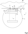
- FIG. 2 A schematic view according to a section according to a plane orthogonal to the axis of the shoe press 1 is shown in Fig. 2 .
- the shoe press 1 coacts with a Yankee cylinder 205.
- the shoe press 1 could, for example, be arranged upstream of the Yankee cylinder 205, or used in a paper machine 2 that does not have a Yankee cylinder 205, but is provided with a series of drying rollers or other drying means. Therefore, the component indicated with 205 in Fig.2 and in the subsequent figures, besides being a Yankee cylinder, can be any other anvil member, preferably in the form of rotating roller or cylinder.
- the shoe press 1 comprises a support beam 3 extending in a cross direction with respect to a direction of feed F of a cellulose ply V on which the shoe press 1 must act.
- the support beam 3 is attached at the ends thereof to a load-bearing structure, not shown.
- a flexible cylindrical sleeve 5, having a rotation axis A substantially parallel to the longitudinal extension of the support beam 3 and hence parallel to the cross machine direction (orthogonal to the direction F of feed of the cellulose ply V through the shoe press 1) extends around the support beam 3.
- the active surface 7A has a profile shaped so as to form a pressure nip 8 with a suitable shape and extension between the outer surface of the flexible cylindrical sleeve 5 and an opposing surface, for example formed by the cylindrical surface of the Yankee cylinder 205.
- lubrication can be of hydrostatic type, as is typical in prior art shoe presses.
- the bearing fluid is dispensed under pressure by means of ducts that end into cavities located on the active surface 7A of the shoe 7 of the press 1.
- the pressure of the bearing fluid is provided by a supply circuit.
- the bearing fluid can be fed from outside the gap and the pressure can be generated through hydrodynamic effect, i.e., through the difference in speed between the inner (movable) surface of the flexible cylindrical sleeve and the (stationary) active surface 7A of the shoe 7.
- the lubrication that is obtained in the gap between shoe 7 and flexible cylindrical sleeve is a lubrication of hydrodynamic type.
- the opposing surface formed by the Yankee cylinder 205 or other opposing member rotates in the opposite direction with respect to the direction of rotation of the cylindrical sleeve 5.
- the peripheral speeds of the flexible cylindrical sleeve 5 and of the opposing surface are substantially identical in modulus.
- the shape of the active surface 7A of the shoe 7 and the shape of the opposing surface of the Yankee cylinder 205 are substantially complementary to each other, so as to form the extended pressure nip 8 of approximately constant height (dimension orthogonal to the opposing surface) along the path of the cellulose ply through the nip 8.
- the Yankee cylinder 205 or other opposing roller rotates at substantially the same feed speed as the speed of one of the endless flexible members 203 that passes through the pressure nip 8 formed between the Yankee cylinder 205 and the portion of flexible cylindrical sleeve 5 pressed against this latter by the shoe 7.
- the shoe 7 is connected to a lever 21 that has a first end 21A hinged to the support beam 3 by means of a hinge that defines a first hinge axis 25 parallel to the support beam 3 and the rotation axis A.
- the lever 21 is thus hinged to the support beam 3 so as to pivot around the first hinge axis 25.
- the shoe 7 is hinged to the lever 21 by means of a hinge that forms a second hinge axis 23.
- the shoe 7 is therefore hinged to the lever 21 so as to rotate around the second hinge axis 23.
- the hinge axis 23 is approximately parallel to the rotation axis A of the flexible cylindrical sleeve 5 and to the first hinge axis 25.
- the lever 21 is connected to thrust actuators 27, which generate a thrust of the shoe 7 against the opposing surface 9.
- the thrust actuators 27 are represented schematically in Fig. 2 and can take various forms, some of which are described below with reference to the remaining figures.
- the shoe press 1 comprises a plurality of actuators 27 aligned along the longitudinal extension of the shoe 7 and of the support beam 3, i.e., parallel to the rotation axis A of the flexible cylindrical sleeve 5.
- Fig. 3 schematically indicates two series of thrust actuators 27A and 27B, each of which comprises a plurality of actuators aligned in the direction of the longitudinal extension of the support beam 3 and of the shoe 7.
- Each actuator 27 can be a hydraulic actuator.
- the actuators 27 are pneumatic actuators, which have a simpler construction and do not require a hydraulic drive circuit.
- the arrangement of two series of actuators 27A, 27B ensures the generation of a sufficiently high linear pressure in the pressure nip 8.
- the actuators 27A, 27B can comprise actuators utilizing synthetic materials, such as synthetic rubber. Actuators of this type can comprise air springs, torpresses or equivalent actuators.
- the actuators can comprise piston-cylinder actuators.
- Fig. 4 shows an embodiment in which multi-stage pneumatic piston-cylinder actuators are used, in which each actuator comprises a cylinder divided into two chambers 28A, 28B, in which two pistons 29A, 29B connected to a single rod 31 move.
- the double actuator, again indicated with 27, thus obtained generates a thrust that is the sum of the thrusts generated on the two pistons 29A, 29B by the pressurized fluid in the two chambers 28A, 28B. In this way, a high thrust is obtained by means of a compact and simple arrangement.
- a lever 21 and a shoe 7 made of a sufficiently flexible material by means of the use of a plurality of actuators 27 controlled independently to one another or in groups, it is possible to generate a linear pressure profile of the desired form along the longitudinal extension of the pressure nip 8, i.e., in cross direction with respect to the direction of feed F (machine direction) of the endless flexible element 203 and of the cellulose ply V adhering thereto.
- each actuator 27 or pair of actuators of the series of actuators 27A, 27B aligned along the rotation axis of the flexible cylindrical sleeve 5 is not strictly necessary.
- the actuators can be divided into a plurality of groups aligned along the longitudinal direction of the support beam 3 and of the shoe 7, i.e., parallel to the rotation axis A of the flexible cylindrical sleeve 5.
- the actuators of each group can be controlled together, and the single groups can be controlled independently to one another.
- Fig.6 schematically shows an improved embodiment in which the lever 21 is divided into a plurality of sections or portions 21C, aligned along the longitudinal extension of the support beam 3 and therefore parallel to the hinge axes 23, 25.
- Fig. 6 is a view according to the line VI-VI of Fig. 3 .
- the configuration of the lever in sections 21C can be adopted for any embodiment, also in Figs. 2 , 4 , and 5 .
- Each section 21C of the lever 21 is stressed by at least one respective thrust actuator 27, or by a couple of thrust actuators 27A, 27B. This division of the lever 21 into sections 21C allows a greater operating flexibility and greater independence of the single actuators in imparting to the shoe 7 a load that is variable along the extension of the pressure nip 8.
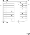
- one or more secondary actuators 35 can be associated with the shoe 7, as schematically shown in Fig. 5 .
- a series of secondary actuators 35 can be provided aligned along the linear extension of the shoe 7.
- the secondary actuators 35 can preferably be pneumatic actuators.
- the secondary actuators 35 can be independent from one another, or divided into groups that are independent from one another.
- Each secondary actuator 35 is interposed between the shoe 7 and the lever 21. If the lever 21 is divided into portions or sections 21C, as shown in Fig.6 , at least one secondary actuator 35 can be provided for each section 21C of the lever 21.
- the secondary actuators 35 allow rotation of the shoe 7 around the second hinge axis 23. In this way it is possible to modify the direction of the resultant of the pressures exerted by the shoe 7 on the opposing surface formed by the Yankee cylinder 205 or other opposing member. If the secondary actuators 35 are independent from one another singularly or in groups, it is possible to impart a resultant of the pressures in variable directions along the longitudinal extension of the shoe 7.
- the endless flexible element defines a closed path around a support beam 3 on which the pressure shoe 7, is mounted with the double hinge around the axes 23, 25, the pressure shoe pressing against the inner surface of the endless flexible element thus forming an extended pressure nip between the outer surface of the endless flexible element and the opposing surface outside the endless flexible element.
- the shoe 7 can be made of a composite material.
- the shoe 7 can be made of a material having a matrix consisting of a polymer resin, containing reinforcing fibers, such as glass fibers or, preferably, carbon fibers.
- the polymer material can be an epoxy resin.
- the shoe 7 can have anisotropic properties, i.e., different physical properties in the different spatial directions.
- the shoe 7 can have a different elastic modulus in machine direction (i.e., the direction of feed of the ply V through the pressure nip 8) and in cross machine direction (i.e., the direction parallel to the longitudinal extension of the support beam 3 and of the shoe 7).
- the shoe 7 can have an elastic modulus in the direction of feed F of the cellulose ply V through the pressure nip 8 that is higher than the elastic modulus in cross machine direction, i.e., parallel to the support beam 3 and transverse to the direction of feed F of the cellulose ply V.
Landscapes
- Paper (AREA)
- Braking Arrangements (AREA)
- Diaphragms For Electromechanical Transducers (AREA)
Claims (20)
- Une presse à sabot (1) comprenant :- un élément flexible sans fin (5) mobile le long d'un circuit fermé ;- une poutre de support (3) logée à l'intérieur de l'élément flexible sans fin (5) ;- un sabot (7) support par la poutre de support (3) et s'étendant parallèlement à la poutre de support (3) à l'intérieur de l'élément flexible sans fin (5) ;- un organe opposé (205) à l'extérieur de l'élément flexible sans fin (5) et formant avec l'élément flexible sans fin (5) un espace de pressage (8) pour le passage d'une couche de cellulose (V), l'espace de pressage étant formé entre l'organe opposé (205) et le sabot (7) ;- une pluralité d'actionneurs (27 ; 27A, 27B) alignés le long de la poutre de support (3) et aptes à exercer une pression sur le sabot (7) contre l'organe opposé au niveau de l'espace de pressage (8) ;dans lequel le sabot (7) est supporté par un levier (21) articulé à la poutre de support (3) autour d'un premier axe d'articulation (25) s'étendant parallèlement à la poutre de support (3), et dans lequel les actionneurs (27; 27A, 27B) sont agencés pour agir sur le levier (21) pour le faire tourner autour du premier axe d'articulation (25) ;caractérisée en ce que le sabot (7) est articulé au levier (21) autour d'un deuxième axe d'articulation (23).
- La presse à sabot (1) selon la revendication 1, dans laquelle le levier (21) comprend une première extrémité (21A) articulée au premier axe d'articulation (25) et une deuxième extrémité (21B).
- La presse à sabot (1) selon la revendication 2, dans laquelle les actionneurs (27 ; 27A, 27B) agissent à proximité de la deuxième extrémité (21B) du levier (21).
- La presse à sabot (1) selon la revendication 2 ou 3, dans laquelle le deuxième axe d'articulation (23) est positionné le long du levier (21) entre la première extrémité (21A) et la deuxième extrémité (21B).
- La presse à sabot (1) selon l'une ou plusieurs des revendications précédentes, dans laquelle les actionneurs (27 ; 27A, 27B) sont des actionneurs pneumatiques, en particulier des cylindres à piston pneumatiques ou des actionneurs à ressort pneumatiques.
- La presse à sabot (1) selon l'une ou plusieurs des revendications précédentes, comprenant deux séries d'actionneurs (27A ; 27B), comprenant chacune une pluralité d'actionneurs alignés dans la direction de la poutre de support (3) et le sabot (7).
- La presse à sabot (1) selon l'une ou plusieurs des revendications précédentes, dans laquelle le levier est divisé en une pluralité de sections (21C) positionnées côté à côte suivant l'extension longitudinale de la poutre de support (3) et du sabot (7).
- La presse à sabot (1) selon la revendication 7, dans laquelle au moins un actionneur (27 ; 27A, 27B) agit sur chaque section (21C) du levier (21).
- La presse à sabot (1) selon la revendication 7, dans laquelle au moins deux actionneurs (27A, 27B) agissent sur chaque section du levier.
- La presse à sabot (1) selon l'une ou plusieurs des revendications 7 à 9, dans laquelle les actionneurs (27 ; 27A, 27B) de chaque section (21C) ou des groupes de sections du levier (21) sont commandés indépendamment les uns des autres.
- La presse à sabot (1) selon l'une ou plusieurs des revendications précédentes, dans laquelle au moins l'un des actionneurs (27 ; 27A, 27B) comprend un actionneur de cylindre à piston à plusieurs étages en série.
- La presse à sabot (1) selon l'une ou plusieurs des revendications précédentes, comprenant au moins un actionneur secondaire (35) agencé pour agir entre le levier (21) et le sabot (7).
- La presse à sabot (1) selon l'une ou plusieurs des revendications précédentes, comprenant une série d'actionneurs secondaires (35), agencés pour agir entre le levier (21) et le sabot (7).
- La presse à sabot selon la revendication 13, dans laquelle les actionnaires secondaires (35) sont commandés indépendamment les uns des autres ou en groupes indépendants.
- La presse à sabot selon l'une ou plusieurs des revendications 12 à 14, dans laquelle chaque actionneur secondaire (35) est un actionneur pneumatique.
- La presse à sabot (1) selon l'une ou plusieurs des revendications précédentes, dans laquelle le sabot (7) est fait d'un matériau anisotropique ayant un module d'élasticité dans la direction d'avancement (F) de la couche de cellulose à travers l'espace de pressage (8) supérieur au module d'élasticité dans la direction perpendiculaire à l'avancement (F) de la couche de cellulose (V) à travers l'espace de pressage (8).
- La presse à sabot (1) selon l'une ou plusieurs des revendications précédentes, dans laquelle le sabot (7) est fait d'un matériau composite, de préférence rempli de fibres, de préférence rempli de fibres de carbone, ou un matériau polymère.
- Un procédé pour presser une couche de cellulose (V), dans lequel la couche de cellulose est guidée à travers un espace de pressage (8) formé entre un élément flexible sans fin (5) mobile autour d'une poutre de support (3) et une organe opposé (205) à l'extérieur de l'élément flexible sans fin (5) au moyen d'un sabot (7) s'étendant parallèlement à la poutre de support (3) et supporté sur un levier (21) articulé à la poutre de support (3) autour d'un premier axe d'articulation (25) et pressé contre une surface interne de l'élément flexible sans fin (5) par une pluralité d'actionneurs alignés le long de la poutre de support (3) au niveau de l'espace de pressage (8) ; dans lequel le sabot est articulé au levier (21) autour d'un deuxième axe d'articulation (23).
- Le procédé selon la revendication 18, dans lequel le sabot (7) est pressé par au moins un actionneur secondaire (35) qui agit entre le sabot (7) et le levier (21).
- Le procédé selon la revendication 18 ou 19, dans lequel un interstice de lubrification entre une surface active (7A) du sabot (7) et une surface interne de l'élément flexible sans fin (5) est soumis à une lubrification hydrodynamique ou à une lubrification hydrostatique ou à une lubrification combinée hydrodynamique et hydrostatique.
Applications Claiming Priority (2)
| Application Number | Priority Date | Filing Date | Title |
|---|---|---|---|
| IT102020000020926A IT202000020926A1 (it) | 2020-09-03 | 2020-09-03 | Pressa a scarpa per carta e relativo metodo |
| PCT/EP2021/072391 WO2022048877A1 (fr) | 2020-09-03 | 2021-08-11 | Presse à sabot pour papier et procédé associé |
Publications (3)
| Publication Number | Publication Date |
|---|---|
| EP4208598A1 EP4208598A1 (fr) | 2023-07-12 |
| EP4208598B1 true EP4208598B1 (fr) | 2024-10-09 |
| EP4208598C0 EP4208598C0 (fr) | 2024-10-09 |
Family
ID=73401930
Family Applications (1)
| Application Number | Title | Priority Date | Filing Date |
|---|---|---|---|
| EP21751595.6A Active EP4208598B1 (fr) | 2020-09-03 | 2021-08-11 | Presse à sabot pour papier et procédé associé |
Country Status (4)
| Country | Link |
|---|---|
| EP (1) | EP4208598B1 (fr) |
| CN (1) | CN116324086B (fr) |
| IT (1) | IT202000020926A1 (fr) |
| WO (1) | WO2022048877A1 (fr) |
Family Cites Families (20)
| Publication number | Priority date | Publication date | Assignee | Title |
|---|---|---|---|---|
| US5167768A (en) * | 1991-11-07 | 1992-12-01 | Beloit Corporation | Wide nip web press and method using a press shoe with two pivots |
| DE19607144A1 (de) * | 1996-02-26 | 1997-08-28 | Voith Sulzer Papiermasch Gmbh | Preßvorrichtung |
| US5997696A (en) * | 1997-09-30 | 1999-12-07 | Valmet-Karlstad Ab | Shoe press |
| US6248210B1 (en) | 1998-11-13 | 2001-06-19 | Fort James Corporation | Method for maximizing water removal in a press nip |
| DE19852635A1 (de) * | 1998-11-14 | 2000-05-18 | Voith Sulzer Papiertech Patent | Blattbildungssystem |
| SE9804347D0 (sv) | 1998-12-16 | 1998-12-16 | Valmet Corp | Method and apparatus for calendering paper |
| SE515484C2 (sv) * | 1999-12-10 | 2001-08-13 | Metso Paper Inc | Pressanordning med förlängt pressnyp för pressning av en löpande papper- eller kartongbana |
| DE10129613A1 (de) | 2001-06-20 | 2003-01-02 | Voith Paper Patent Gmbh | Verfahren und Vorrichtung zur Herstellung einer mit einer dreidimensionalen Oberflächenstruktur versehenen Faserstoffbahn |
| JP2003208338A (ja) * | 2002-01-10 | 2003-07-25 | Canon Inc | 統合監視システム |
| US7150110B2 (en) | 2002-01-24 | 2006-12-19 | Voith Paper Patent Gmbh | Method and an apparatus for manufacturing a fiber web provided with a three-dimensional surface structure |
| JP3611322B2 (ja) * | 2002-02-28 | 2005-01-19 | 三菱重工業株式会社 | シュープレス装置 |
| JP3680053B2 (ja) * | 2002-10-22 | 2005-08-10 | 三菱重工業株式会社 | 紙のカレンダ処理装置及び紙のカレンダ処理方法 |
| FI114031B (fi) | 2003-03-04 | 2004-07-30 | Metso Paper Inc | Menetelmä paperirainan puristamiseksi ja paperirainan puristuslaite |
| US7096693B2 (en) | 2003-03-07 | 2006-08-29 | Shima Seiki Mfg., Ltd. | Knitting method for knitting fabric |
| US7527708B2 (en) * | 2003-10-21 | 2009-05-05 | Metso Paper Karlstad Ab | Support body, holding device therefor, apparatus with said body for treatment of a web, and methods of forming an extended nip in the apparatus and controlling load in the nip |
| JP2008121170A (ja) * | 2006-11-15 | 2008-05-29 | Mitsubishi Heavy Ind Ltd | シュープレス装置及びその加圧脱水方法 |
| FI20115099L (fi) | 2011-01-31 | 2012-08-01 | Metso Fabrics Oy | Kenkäpuristinhihna, menetelmä sen valmistamiseksi ja käyttö kenkäpuristimessa |
| SE538098C2 (sv) * | 2013-11-14 | 2016-03-01 | Valmet Aktiebolag | En långnypsvals med ett stödelement för behandling av en fiberbana |
| US10697120B2 (en) | 2017-08-08 | 2020-06-30 | Gpcp Ip Holdings Llc | Methods of making paper products using a patterned cylinder |
| JP2021510776A (ja) | 2018-01-11 | 2021-04-30 | ア チエリ パペル ソチエタ ペル アチオーニ | 薄葉紙製造装置及び方法 |
-
2020
- 2020-09-03 IT IT102020000020926A patent/IT202000020926A1/it unknown
-
2021
- 2021-08-11 EP EP21751595.6A patent/EP4208598B1/fr active Active
- 2021-08-11 CN CN202180067869.6A patent/CN116324086B/zh active Active
- 2021-08-11 WO PCT/EP2021/072391 patent/WO2022048877A1/fr not_active Ceased
Also Published As
| Publication number | Publication date |
|---|---|
| EP4208598A1 (fr) | 2023-07-12 |
| CN116324086A (zh) | 2023-06-23 |
| WO2022048877A1 (fr) | 2022-03-10 |
| IT202000020926A1 (it) | 2022-03-03 |
| EP4208598C0 (fr) | 2024-10-09 |
| BR112023003733A2 (pt) | 2023-03-28 |
| CN116324086B (zh) | 2025-04-01 |
Similar Documents
| Publication | Publication Date | Title |
|---|---|---|
| USRE30268E (en) | Hydrodynamically loaded web press with slipper bearing shoes | |
| CN101426978B (zh) | 用于处理纤维幅材的设备和方法以及用于该设备的支撑体和支撑体组件 | |
| US3804707A (en) | Papermaking press with inflatable rolls having thin deformable outer shells | |
| JPH07122230B2 (ja) | 広ニップ型ウェットプレス及びその圧力輪郭の制御方法 | |
| EP2737125B1 (fr) | Machine à papier pour fabriquer du papier de soie et procédé d'exploitation d'une machine à papier | |
| CA2012726C (fr) | Procede de pressage a chaud comportant un dispositif de sechage | |
| JP4278298B2 (ja) | 拡張ニッププレス | |
| EP4208598B1 (fr) | Presse à sabot pour papier et procédé associé | |
| US5938895A (en) | Calender having moisture profile control | |
| EP1209285A2 (fr) | Système de commande pour messurer un écartement | |
| JP2023552566A (ja) | 支持体およびそのような支持体を備える抄紙機 | |
| CN219010808U (zh) | 一种处理纸幅的压榨装置 | |
| AU2006240290B2 (en) | Extended couch nip on cylinder former | |
| CN107938419A (zh) | 一种卫生纸机软靴压装置及其应用 | |
| US20060237157A1 (en) | Extended couch nip on cylinder former | |
| EP1605096B1 (fr) | Presse à patin | |
| BR112023003733B1 (pt) | Prensa de sapata para papel e método relacionado | |
| US6485612B1 (en) | Air press assembly for use in a paper-making machine | |
| JPS6146598B2 (fr) | ||
| FI116080B (fi) | Kartonkituote ja menetelmä sen valmistamiseksi | |
| JP2006508268A (ja) | 板紙製品とその製法 | |
| JP2003049379A (ja) | 拡張ニップロールプレス | |
| US20080251223A1 (en) | Board Product and Method of Making the Same | |
| WO2025247704A1 (fr) | Machine à papier conçue pour former une ligne de contact de transfert courte | |
| US20060118256A1 (en) | Lwc paper product and method of making the same |
Legal Events
| Date | Code | Title | Description |
|---|---|---|---|
| STAA | Information on the status of an ep patent application or granted ep patent |
Free format text: STATUS: UNKNOWN |
|
| STAA | Information on the status of an ep patent application or granted ep patent |
Free format text: STATUS: THE INTERNATIONAL PUBLICATION HAS BEEN MADE |
|
| PUAI | Public reference made under article 153(3) epc to a published international application that has entered the european phase |
Free format text: ORIGINAL CODE: 0009012 |
|
| STAA | Information on the status of an ep patent application or granted ep patent |
Free format text: STATUS: REQUEST FOR EXAMINATION WAS MADE |
|
| 17P | Request for examination filed |
Effective date: 20230301 |
|
| AK | Designated contracting states |
Kind code of ref document: A1 Designated state(s): AL AT BE BG CH CY CZ DE DK EE ES FI FR GB GR HR HU IE IS IT LI LT LU LV MC MK MT NL NO PL PT RO RS SE SI SK SM TR |
|
| DAV | Request for validation of the european patent (deleted) | ||
| DAX | Request for extension of the european patent (deleted) | ||
| GRAP | Despatch of communication of intention to grant a patent |
Free format text: ORIGINAL CODE: EPIDOSNIGR1 |
|
| STAA | Information on the status of an ep patent application or granted ep patent |
Free format text: STATUS: GRANT OF PATENT IS INTENDED |
|
| INTG | Intention to grant announced |
Effective date: 20240502 |
|
| GRAS | Grant fee paid |
Free format text: ORIGINAL CODE: EPIDOSNIGR3 |
|
| GRAA | (expected) grant |
Free format text: ORIGINAL CODE: 0009210 |
|
| STAA | Information on the status of an ep patent application or granted ep patent |
Free format text: STATUS: THE PATENT HAS BEEN GRANTED |
|
| AK | Designated contracting states |
Kind code of ref document: B1 Designated state(s): AL AT BE BG CH CY CZ DE DK EE ES FI FR GB GR HR HU IE IS IT LI LT LU LV MC MK MT NL NO PL PT RO RS SE SI SK SM TR |
|
| REG | Reference to a national code |
Ref country code: CH Ref legal event code: EP |
|
| REG | Reference to a national code |
Ref country code: DE Ref legal event code: R096 Ref document number: 602021019995 Country of ref document: DE |
|
| REG | Reference to a national code |
Ref country code: IE Ref legal event code: FG4D |
|
| U01 | Request for unitary effect filed |
Effective date: 20241107 |
|
| U07 | Unitary effect registered |
Designated state(s): AT BE BG DE DK EE FI FR IT LT LU LV MT NL PT RO SE SI Effective date: 20241115 |
|
| PG25 | Lapsed in a contracting state [announced via postgrant information from national office to epo] |
Ref country code: HR Free format text: LAPSE BECAUSE OF FAILURE TO SUBMIT A TRANSLATION OF THE DESCRIPTION OR TO PAY THE FEE WITHIN THE PRESCRIBED TIME-LIMIT Effective date: 20241009 Ref country code: IS Free format text: LAPSE BECAUSE OF FAILURE TO SUBMIT A TRANSLATION OF THE DESCRIPTION OR TO PAY THE FEE WITHIN THE PRESCRIBED TIME-LIMIT Effective date: 20250209 |
|
| PG25 | Lapsed in a contracting state [announced via postgrant information from national office to epo] |
Ref country code: ES Free format text: LAPSE BECAUSE OF FAILURE TO SUBMIT A TRANSLATION OF THE DESCRIPTION OR TO PAY THE FEE WITHIN THE PRESCRIBED TIME-LIMIT Effective date: 20241009 |
|
| PG25 | Lapsed in a contracting state [announced via postgrant information from national office to epo] |
Ref country code: NO Free format text: LAPSE BECAUSE OF FAILURE TO SUBMIT A TRANSLATION OF THE DESCRIPTION OR TO PAY THE FEE WITHIN THE PRESCRIBED TIME-LIMIT Effective date: 20250109 |
|
| PG25 | Lapsed in a contracting state [announced via postgrant information from national office to epo] |
Ref country code: GR Free format text: LAPSE BECAUSE OF FAILURE TO SUBMIT A TRANSLATION OF THE DESCRIPTION OR TO PAY THE FEE WITHIN THE PRESCRIBED TIME-LIMIT Effective date: 20250110 |
|
| PG25 | Lapsed in a contracting state [announced via postgrant information from national office to epo] |
Ref country code: PL Free format text: LAPSE BECAUSE OF FAILURE TO SUBMIT A TRANSLATION OF THE DESCRIPTION OR TO PAY THE FEE WITHIN THE PRESCRIBED TIME-LIMIT Effective date: 20241009 |
|
| PG25 | Lapsed in a contracting state [announced via postgrant information from national office to epo] |
Ref country code: RS Free format text: LAPSE BECAUSE OF FAILURE TO SUBMIT A TRANSLATION OF THE DESCRIPTION OR TO PAY THE FEE WITHIN THE PRESCRIBED TIME-LIMIT Effective date: 20250109 |
|
| PG25 | Lapsed in a contracting state [announced via postgrant information from national office to epo] |
Ref country code: SM Free format text: LAPSE BECAUSE OF FAILURE TO SUBMIT A TRANSLATION OF THE DESCRIPTION OR TO PAY THE FEE WITHIN THE PRESCRIBED TIME-LIMIT Effective date: 20241009 |
|
| PG25 | Lapsed in a contracting state [announced via postgrant information from national office to epo] |
Ref country code: SK Free format text: LAPSE BECAUSE OF FAILURE TO SUBMIT A TRANSLATION OF THE DESCRIPTION OR TO PAY THE FEE WITHIN THE PRESCRIBED TIME-LIMIT Effective date: 20241009 |
|
| PG25 | Lapsed in a contracting state [announced via postgrant information from national office to epo] |
Ref country code: CZ Free format text: LAPSE BECAUSE OF FAILURE TO SUBMIT A TRANSLATION OF THE DESCRIPTION OR TO PAY THE FEE WITHIN THE PRESCRIBED TIME-LIMIT Effective date: 20241009 |
|
| PLBE | No opposition filed within time limit |
Free format text: ORIGINAL CODE: 0009261 |
|
| STAA | Information on the status of an ep patent application or granted ep patent |
Free format text: STATUS: NO OPPOSITION FILED WITHIN TIME LIMIT |
|
| 26N | No opposition filed |
Effective date: 20250710 |
|
| U20 | Renewal fee for the european patent with unitary effect paid |
Year of fee payment: 5 Effective date: 20250826 |
|
| REG | Reference to a national code |
Ref country code: CH Ref legal event code: H13 Free format text: ST27 STATUS EVENT CODE: U-0-0-H10-H13 (AS PROVIDED BY THE NATIONAL OFFICE) Effective date: 20260324 |
|
| PG25 | Lapsed in a contracting state [announced via postgrant information from national office to epo] |
Ref country code: MC Free format text: LAPSE BECAUSE OF FAILURE TO SUBMIT A TRANSLATION OF THE DESCRIPTION OR TO PAY THE FEE WITHIN THE PRESCRIBED TIME-LIMIT Effective date: 20241009 |
|
| U1H | Name or address of the proprietor changed after the registration of the unitary effect |
Owner name: ANDRITZ PULP & PAPER ITALY S.R.L.; IT |